Page is loading ...

Page 1
©2021 Whelen Engineering Company Inc.
Form No.14D18E (032822)
Installation Guide:
WeCanX™ V2V Sync Module
51 Winthrop Road,
Chester, Connecticut 06412-0684
Phone: (860) 526-9504
Internet: www.whelen.com
Sales e-mail: autosale@whelen.com
Customer Service e-mail: [email protected]
For warranty information regarding this product, visit www.whelen.com/warranty
Automotive: Serial Communications
WARNING: This product can expose you to chemicals including Lead which is known to the State of California to cause cancer and birth defects or
other reproductive harm. For more information go to www.P65Warnings.ca.gov.
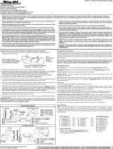
Mounting the V2V Module
WINDOW
MOUNTING
Mounting to Dash, Rear Deck or other surface:
Mounting to Vehicle:
It is recommended you mount the module to the dashboard or rear deck of the vehicle however it can be mounted to any surface or
window. If mounted to a window it is recommended to use 3M SJ3560 Dual Lock tape. The module be mounted face upmust
(side with logo). This is the side that receives the signal. If mounted to a window, the face must point out of the vehicle.
8 X 3/4 Phillips
Pan Head
Sheet Metal
Screw
Mounting Surface
Front (side with logo)
of Module must face up
IMPORTANT: an module andCle
mounting surface with an
isopropyl alcohol wipe prior to
mounting.
It is the responsibility of the
installation technician to
make sure the installation
and operation of this product
will not interfere with or
compromise the operation or
efficiency of any other vehicle
equipment!
IMPORTANT!
Before returning the vehicle
to active service, visually
confirm the proper operation
of this product, as well as all
vehicle components or
equipment.

Page 2
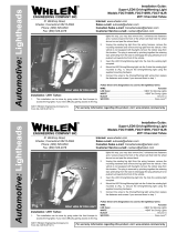
RED
GRN
GRY
BLK
GRN
BLK/WHT
GRY
J18
Core Main Box
1
2
3
(+)
Battery
Fuse @
1 AMP
(-)
S ecificationsp:
Input Voltage:+10-30 VDC
Current Draw:30 mA
Wire as shown ainstalling
customer supplied fuse into
Pthe power w . lug theire
connector into J18 of Core
usingMain Box and operate
tthe Core system.
V2V Sync Module:
POWERED BY
TM
MOUNT THIS SIDE
FACING TOWARD WINDOW
FOR GPS ACCURACY:
DIAGNOSTIC INDICATOR:
RED:No GPS
GREEN:GPS / Weak Signal
GPS / Strong SignalBLUE:
V2V SYNC MODULE
MOUNT THIS SIDE
FACING TOWARD WINDOW
FOR GPS ACCURACY:
Note: BLK/WHT wire from J18 port is a shield wire.
It is recommended to ground shield wire on
both ends to help reduce unwanted
electromagnetic interference.
Note: On initial power up, the device may 15 minutes ofrequire
operation before siren tones will synchronize.
Power must remain connected to the device between ignition cycles
to remain synchronized.
/