Page is loading ...

Page 1
©1996 Whelen Engineering Company Inc.
Form No.13092F (072707)
Automotive: Sirens/Switches
For warranty information regarding this product, visit www.whelen.com/warranty
DANGER! Sirens produce extremely loud emergency warning tones! Exposure to these tones without proper and adequate hearing protection, could
cause ear damage and/or hearing loss! The Occupational Safety & Health Administration (www.osha.gov) provides information necessary to determine
safe exposure times in Occupational Noise Exposure Section 1910.95. Until you have determined the safe exposure times for your specific application,
operators and anyone else in the immediate vicinity should be required to wear an approved hearing protection device. Failure to follow this
recommendation could cause hearing loss!
• Proper installation of this product requires the installer to have a good understanding of automotive electronics, systems and procedures.
• Whelen Engineering requires the use of waterproof butt splices and/or connectors if that connector could be exposed to moisture.
• Any holes, either created or utilized by this product, should be made both air- and watertight using a sealant recommended by your vehicle
manufacturer.
• Failure to use specified installation parts and/or hardware will void the product warranty.
• If mounting this product requires drilling holes, the installer MUST be sure that no vehicle components or other vital parts could be damaged
by the drilling process. Check both sides of the mounting surface before drilling begins. Also de-burr the holes and remove any metal shards
or remnants. Install grommets into all wire passage holes.
• If this manual states that this product may be mounted with suction cups, magnets, tape or Velcro®, clean the mounting surface with a 50/50
mix of isopropyl alcohol and water and dry thoroughly.
• Do not install this product or route any wires in the deployment area of your air bag. Equipment mounted or located in the air bag deployment
area will damage or reduce the effectiveness of the air bag, or become a projectile that could cause serious personal injury or death. Refer to
your vehicle owner’s manual for the air bag deployment area. The User/Installer assumes full responsibility to determine proper mounting
location, based on providing ultimate safety to all passengers inside the vehicle.
• For this product to operate at optimum efficiency, a good electrical connection to chassis ground must be made. The recommended
procedure requires the product ground wire to be connected directly to the NEGATIVE (-)
battery post (this does not include products that use cigar power cords).
• If this product uses a remote device for activation or control, make sure that this device is
located in an area that allows both the vehicle and the device to be operated safely in any
driving condition.
• It is recommended that these instructions be stored in a safe place and referred to when
performing maintenance and/or reinstallation of this product.
• FAILURE TO FOLLOW THESE SAFETY PRECAUTIONS AND INSTRUCTIONS COULD RESULT
IN DAMAGE TO THE PRODUCT OR VEHICLE AND/OR SERIOUS INJURY TO YOU AND YOUR
PASSENGERS!
CAUTION
Loud siren noise can cause
hearing damage and/or loss.
Refer to OSHA Section 1910.95 prior
to putting ANY siren into service!
Wear
Protection!
ACTIVATION OF THIS
SIREN MAY DAMAGE
UNPROTECTED EARS!
Warnings to Installers
Whelen’s emergency vehicle warning devices must be properly mounted and wired in order to be effective and safe. Read and follow all of Whelen’s written
instructions when installing or using this device. Emergency vehicles are often operated under high speed stressful conditions which must be accounted for
when installing all emergency warning devices. Controls should be placed within convenient reach of the operator so that they can operate the system without
taking their eyes off the roadway. Emergency warning devices can require high electrical voltages and/or currents. Properly protect and use caution around
live electrical connections.Grounding or shorting of electrical connections can cause high current arcing, which can cause personal injury and/or vehicle
damage, including fire. Many electronic devices used in emergency vehicles can create or be affected by electromagnetic interference. Therefore, after
installation of any electronic device it is necessary to test all electronic equipment simultaneously to insure that they operate free of interference from other
components within the vehicle. Never power emergency warning equipment from the same circuit or share the same grounding circuit with radio
communication equipment. All devices should be mounted in accordance with the manufacturer’s instructions and securely fastened to vehicle elements of
sufficient strength to withstand the forces applied to the device. Driver and/or passenger air bags (SRS) will affect the way equipment should be mounted. This
device should be mounted by permanent installation and within the zones specified by the vehicle manufacturer, if any. Any device mounted in the deployment
area of an air bag will damage or reduce the effectiveness of the air bag and may damage or dislodge the device. Installer must be sure that this device, its
mounting hardware and electrical supply wiring does not interfere with the air bag or the SRS wiring or sensors. Mounting the unit inside the vehicle by a
method other than permanent installation is not recommended as unit may become dislodged during swerving; sudden braking or collision. Failure to follow
instructions can result in personal injury. Whelen assumes no liability for any loss resulting from the use of this warning device. PROPER INSTALLATION
COMBINED WITH OPERATOR TRAINING IN THE PROPER USE OF EMERGENCY WARNING DEVICES IS ESSENTIAL TO INSURE THE SAFETY OF
EMERGENCY PERSONNEL AND THE PUBLIC.
Warnings to Users
Whelen’s emergency vehicle warning devices are intended to alert other operators and pedestrians to the presence and operation of emergency vehicles and
personnel. However, the use of this or any other Whelen emergency warning device does not guarantee that you will have the right-of-way or that other
drivers and pedestrians will properly heed an emergency warning signal. Never assume you have the right-of-way. It is your responsibility to proceed safely
before entering an intersection, driving against traffic, responding at a high rate of speed, or walking on or around traffic lanes. Emergency vehicle warning
devices should be tested on a daily basis to ensure that they operate properly. When in actual use, the operator must ensure that both visual and audible
warnings are not blocked by vehicle components (i.e.: open trunks or compartment doors), people, vehicles, or other obstructions. It is the user’s responsibility
to understand and obey all laws regarding emergency warning devices. The user should be familiar with all applicable laws and regulations prior to the use of
any emergency vehicle warning device. Whelen’s audible warning devices are designed to project sound in a forward direction away from the vehicle
occupants. However, because sustained periodic exposure to loud sounds can cause hearing loss, all audible warning devices should be installed and
operated in accordance with the standards established by the National Fire Protection Association.
Safety First
This document provides all the necessary information to allow your Whelen product to be properly and safely installed. Before beginning the installation and/or
operation of your new product, the installation technician and operator must read this manual completely. Important information is contained herein that could
prevent serious injury or damage.
WARNING: This product may contain chemicals known to the State of California to cause cancer and birth defects or other reproductive harm. For
more information, visit www.whelen.com/regulatory.
Installation Guide:
295HFS2 Series Siren
51 Winthrop Road
Chester, Connecticut 06412-0684
Phone: (860) 526-9504
Internet: www.whelen.com
Sales e-mail: autosale@whelen.com
Customer Service e-mail: [email protected]
®
ENGINEERING COMPANY INC.

Page 2
WARNING!
DISCONNECTING THE VEHICLE BRAKE LAMP
CIRCUIT USING ANY SIRENS WITH RELAY OUTPUTS
OR SWITCH CONTROLLERS COULD CAUSE
VEHICLE OR PROPERTY DAMAGE, SERIOUS INJURY
OR EVEN DEATH.
DISABLING THIS CIRCUIT IS A VIOLATION OF THE
FEDERAL MOTOR VEHICLE SAFETY STANDARD
FOR THE THIRD BRAKE LIGHT, AS WELL AS REAR
BRAKE LIGHTS.
FUNCTIONS THAT BLACK OUT THE REAR BRAKE
LIGHTS (SOMETIMES CALLED “BRAKE LIGHT CUT
OUT”) MAY INTERFERE WITH THE BRAKE SHIFT
LOCK MECHANISM, AND CAUSE THE VEHICLE TO
MOVE UNEXPECTEDLY AND DANGEROUSLY.
DISCONNECTING THE BRAKE LIGHTS IN ANY WAY
IS AT YOUR OWN
RISK AND IS NOT RECOMMENDED
BY WHELEN.

Page 3
READ BEFORE INSTALLING!!!
Do not install this product or route any wires in the deployment
area of your air bag. Equipment mounted or located in
the air bag deployment area will damage or reduce the
effectiveness of the air bag or become a projectile that could
cause serious personal injury or death. Refer to your vehicle
owner's manual for the air bag deployment area.
The User/Installer assumes full responsibility to determine the
proper mounting location, based on providing ultimate safety
to all passengers inside the vehicle. Whelen Engineering Co.
assumes no liability or responsibility for determining individual
applications or exact installation location criteria.
5.875"
5-7/8"
2.65"
2-21/32"
2.938"
2-15/16"
2.50"
2-1/2"
Mounting
Screws
(Qty. 4)
CUT-OUT THIS AREACUT-OUT THIS AREACUT-OUT THIS AREA
1.25"
1-1/4"
5.00”
5"
2.50"
2-1/2"
1.325"
1-21/64
SIDE VIEW
2.375"
2-3/8"
2.95"
2-61/64"
R
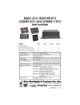
The 295HFS2, although technologically advanced, is simple to
install. the 295HFS2 is specially designed for dash (or panel)
mounting. WARNING: Mounting will require drilling. It is
absolutely necessary to make sure that no vehicle components
behind the mounting area will be damaged. If damage is
possible, select another location.
NOTE: Before starting read all warnings on next page.
Installation: Control Head
The flush mount unit can be mounted in a console, dash or
other suitable location. Using the measurements below, cut-out
the hole for the control head, then slide the unit in and drill the 4
holes for the customer supplied mounting hardware.
IMPORTANT: Template is not to scale. Check measurements
before drilling. Measurements are given in decimals and
fractions for your convenience. For a more accurate
measurement and installation you should
use the decimals.
Installation: Amplifier
1. From inside the trunk, position the amplifier against the
vertical trunk wall behind the rear seat and mark off the 4
mounting holes using a scribe or other suitable tool. Be
sure that the remote amplifier fits properly and does not
interfere with any parts of the trunk or seat back.
2. Carefully drill the indicated holes using an appropriately
sized drill bit, then, using the supplied sheet metal screws,
secure the remote amplifier to the vertical trunk wall.

Page 4
Connecting the 12-Position Input Harness:
RED & BLACK - Power & Ground Wires:
1. Insert wiring harness into it’s port.
2. Splice the 2 RED (Power) wires together, then extend this
single RED wire toward the vehicle battery. Splice the 2
BLACK (Ground) wires together and extend this single
BLACK wire toward the vehicle battery. To pass the RED
and BLACK wires through, you may have to drill a hole in
the firewall. Be sure there are no components that could be
damaged. Insert a grommet in the hole to protect the wires.
WARNING: All customer supplied wires that connect to the
positive terminal of the battery must be sized to supply at
least 125% of the maximum operating current and FUSED
at the battery to carry that load. DO NOT USE CIRCUIT
BREAKERS WITH THIS PRODUCT (see customer wire size
chart)!
3. Install a 20 amp fuse block (user supplied) on the end of
the RED wire. Note: Remove the fuse from the fuse block
before connecting any wires to the battery.
4. Connect the fuse block wire to the POSITIVE (+) terminal
on the battery. There must not be more than two (2) feet of
wire between the fuse block and the battery. As the wire
between the fuse and the battery is unprotected, do not
allow this wire to come in contact with any other wires.
5. Connect the BLACK wire to the factory chassis ground
adjacent to the battery.
YELLOW, ORANGE & BROWN - Speaker Wires:
Note: This section outlines a two-speaker installation. If a one-
speaker installation is used, cut and cap the ORANGE wire,
skip step 3 and connect the BROWN wire to the NEGATIVE
terminal of Speaker #1.
1. Route the YELLOW, ORANGE and BROWN wires toward
the vehicle’s siren speakers.
2. Connect the YELLOW wire to the POSITIVE speaker
connection on Speaker 1.
3. Connect the ORANGE wire to the POSITIVE speaker
connection on Speaker 2.
4. Connect the BROWN wire to the NEGATIVE speaker
connection on Speaker 2.
5. Splice a wire from the NEGATIVE connection on speaker 2
to the NEGATIVE connection on Speaker 1.
BLUE - Radio Rebroadcast Wires:
Note: The two BLUE wires are used to connect your two-way
radio’s external speaker to the 295HFS2 for radio rebroadcast.
This is an optional connection and does not effect the other
operations of the 295HFS2.
1. Locate the two wires that connect the external speaker to
the vehicle’s two-way radio.
2. Cut one of these wires and splice one of the BLUE wires
into this circuit.
3. Cut the remaining speaker wire and splice the remaining
BLUE wire into this circuit.
NOTE: Radio rebroadcast will NOT
work with amplified remote
speakers. If your remote speaker is amplified (i.e.: contains a
power amp circuit in the speaker assembly), do not enable the
radio rebroadcast feature.
Connecting the 8-Position Siren Connector:
RED - Power:
1. Insert the 8-position siren connector into its port.
2. Route the RED wire to the POSITIVE (+) battery terminal.
3. Install a 3 amp fuse block (user supplied) on the end of the
RED wire. NOTE: Remove the fuse from the fuse block
before connecting any wires to the battery.
WARNING: All customer supplied wires that connect to the
positive terminal of the battery must be sized to supply at
least 125% of the maximum operating current and FUSED
at the battery to carry that load. DO NOT USE CIRCUIT
BREAKERS WITH THIS PRODUCT (see customer wire size
chart)!
YELLOW - Dimmer Control:
1. Route the YELLOW wire along the factory wire harness
toward the driver’s side rocker sill plate location.
2. Follow the factory harness towards the firewall. Do not go
beyond the firewall.
3. Connect the YELLOW wire to the dashlight dimmer circuit
located under the dashboard. Depending on the type of
vehicle, there are several good locations to access this
circuit. For example; the ashtray courtesy light in a Crown
Victoria is connected to the dimmer circuit.
WHITE & GREY - Horn Relay
1. Route the WHITE and GREY wires along the factory wire
harness and through the firewall at the same point as the
RED and BLACK wires.
2. Locate your vehicle’s horn relay and route the WHITE and
GREY wires to this. If possible, follow the factory wire
harness to this relay.
3. Locate the wire that connects the vehicle horn to the horn
relay. Cut this wire.
4. Connect WHITE wire to wire coming from horn relay.
5. Connect the GREY wire to the wire coming from the horn.
BLACK/WHITE - Remote Siren Tone Activation
An auxiliary switch can be connected to automatically activate
siren tones. If this is desired, connect the BLACK/WHITE wire
to a ground activated switch.
Connecting the Control Head to the Remote Amplifier:
1. Remove the rear seat (both sections) from the vehicle.
2. Remove the rear, driver side rocker sill plate.
3. Extend the VIOLET and GREEN wires (from the 8-position
connector) to the remote amplifier.
4. Connect the GREEN wire from the control head to the
GREEN wire from the amplifier.
5. Connect the VIOLET wire from the control head to the
VIOLET wire from the amplifier (see wiring diagram).

Page 5
VOLSPK2
SPK1
PIER
FRONT of CONTROL HEAD
Microphone
Volume Adjust.
BACK of AMPLIFIER
Radio Rebroadcast
Adjustment Screw
20 AMP
To Adjust the Radio Repeat Levels: Before using the 295HFS2, the Radio Repeat output volume and microphone volume
(PA) must be adjusted to satisfactory operating levels. To adjust this level, a small, flat blade screwdriver is needed. Locate the
Radio Repeat adjustment port (potentiometer) to the left of the 12 position input port on the back of the remote amplifier. Set the vol-
ume level of the vehicle’s two-way radio to its normal operating
volume. Turn the Rotory Knob on the control head to RAD to acti-
vate Radio Repeat. Insert the screwdriver in the Radio Repeat
adjustment port and turn in a clockwise direction to increase the
sound level.
Microphone Volume (PA) Locate the microphone adjustment port
(potentiometer) below the microphone cord. With the vehicle in an
enclosed area, turn the Rotory Knob to PA and speak into the
microphone. While speaking, turn the screwdriver in a clockwise
direction to increase the volume. Continue to increase the PA volume until audio feedback occurs, then turn the screwdriver in a
counter-clockwise direction until the feedback is eliminated.
SI-TEST
®
& DIAGNOSTIC
INDICATORS
- SI-TEST is a
diagnostic feature and allows the
operator to confirm the proper
operation of the siren speakers
connected to the unit without
activating an audible siren tone. To
initiate the SI-TEST cycle, set the
rotary knob to the RAD position. Now
press and release the MAN button. As the siren is tested, its
diagnostic indicator will turn on steady for about 1.5 seconds if
no problems are detected. If the indicator flashes, or does not
light at all, a problem with either the siren, speakers, or wiring
has been detected. Check the wire connections of the failed
speaker and repeat the SI-TEST. If the speaker fails to test
again, have the siren inspected by a qualified technician.
WARNING: Installed speakers are tested by generating an
ultra-high frequency tone through each speaker. Although these
tones are inaudible to humans, be sure there is nobody within 5
feet of the speakers when SI-TEST
is running.
DIAGNOSTIC INDICATORS: This unit has two diagnostic indi-
cators on the front panel which are used to indicate fault condi-
tions with your siren system. The table below lists the type of
fault and the indicators response. If the indicator is on steady
while a tone is in use, this implies that there is no fault with the
associated speaker output.
Operating the 295HFRS Controls
POWER SWITCH - This switch has
two positions: Down / Off and Up / On.
When this switch is in the Off position,
the 295HFS2 will not function. When
the switch is in the On position the siren
is functional and may be activated.
NOTE: If the 295HFS2 is connected to
the vehicle’s horn ring circuit, the
vehicle horn is disabled when the power
switch is in the ON position.
MAN BUTTON - The Manual button
generates a variety of tones,
depending on what position the rotary
knob is in. For further explanation of
this button’s function, refer to Rotary
Switch Operations.
ROTARY SWITCH - The Rotary Knob
controls the siren and PA (Public
Address) functions. There are 7
positions that may be selected. Each
position and it’s function is outlined
under “Rotary Switch Operations”.
POWER
ON
FUNCTION
HF
MAN
PA
YELP
WAIL
MAN
PA
RAD
VOL21
MICSPKSPK
PIER
Fault Condition Diagnostic Indicators Response
Under Voltage Speaker LED #2 will be in a double flash mode (2 quick flashes followed by a longer pause) and the siren
tones will not operate.
Over Voltage Speaker LED #1 will be in a double flash mode (2 quick flashes followed by a longer pause) and the siren
tones will not operate.
Speaker #1 Speaker LED # 1 will be in a single flash mode (the LED will be on and off an equal amount of time) and
Short Circuit the siren tones will not operate.
Speaker #2 Speaker LED #2 will be in a single flash mode (the LED will be on and off an equal amount of time) and
Short Circuit the siren tones will not operate.
Speaker #1 Speaker LED #1 will be off (having a single speaker system will always cause this condition for the speaker
Open Circuit output not in use) all tones will continue to operate.
Speaker #2 Speaker LED #2 will be off (having a single speaker system will always cause this condition for the speaker
Open Circuit output not in use) all tones will continue to operate.

Page 6
Rotary Switch Operations
RAD (Radio Repeat) - When the rotary knob is in the RAD
position, any signal that is received by the vehicle’s two-way
radio will be simultaneously broadcast over the vehicle’s loud-
speaker (unit must be connected to the two-way radio as out-
lined in this manual).
With the Rotary Switch in this Position:
• Pressing the MAN button will result in SI-TEST®.
• Activating the HORN RING input results in the AIRHORN
tone until the HORN RING input is released.
• Activating the AUX ENABLE input has no effect.
PA (Public Address) - When the rotary switch is in this
position the siren is in a standby state where no tones have
been activated, but is waiting for another action to be taken by
the operator. This position is often the best choice when public
address is required.
With the Rotary Switch in this Position:
• Pressing the MAN button will result in the AIRHORN tone
until the MAN switch is released.
• Activating the HORN RING input will result in the AIR-
HORN tone until the HORN RING input is released.
• Activating the AUX ENABLE input will result in a repeating
WAIL tone.
MAN (Manual Siren) - When the rotary switch is in this position
the siren is in a standby state where no tones have been
activated, but is waiting for another action to be taken by the
operator. This position is often the best choice when manual
operation of the siren is desired.
With the Rotary Switch in this Position:
• Pressing the MAN switch will result in a WAIL tone
ramping up to peak frequency and stopping when the MAN
switch is released.
• Activating the HORN RING input will result in a WAIL tone
ramping up to the peek frequency and stopping when the
HORN RING input is released.
• Activating the AUX enable input will result in a repeating
WAIL tone.
HF (Hands Free Operation) - When the rotary knob is in the
HF position, the siren functions are placed in a standby mode.
Siren tones are activated by a single ‘tap’ on the MAN button or
a single tap on the vehicle’s steering wheel horn ring (if the
vehicle’s horn has been wired to the HORN RING input). The
first tap produces a Wail tone (a steady rise and fall tone). A
second tap produces a Yelp tone (a fast rise and fall tone.) A
third tap produces a Piercer™ tone (an extremely fast rise and
fall tone). The next tap returns the siren to a wail tone and the
cycle repeats itself. Two quick, successive taps will stop the
siren.
With the Rotary Switch in this Position:
• Pressing the MAN button will result in the HF cycle as
described above.
• Activating the HORN RING input will result in the HF cycle
as described above.
• Activating the AUX ENABLE input will start the HF cycle.
WAIL (Wail Tone) - When the rotary knob is in the WAIL
position, a steady, rise and fall tone (wail) is produced.
With the Rotary Switch in this Position:
• Pressing the MAN button will change the siren tone to a
yelp pattern (a fast rise and fall tone). Pressing the MAN
button a second time returns it back to a wail tone.
• Activating the HORN RING input will change the siren tone
to a yelp pattern (a fast rise and fall tone). Activating the
HORN RING input again returns it back to a wail tone.
• Activating the AUX ENABLE input has no effect.
YELP (Yelp Tone) - When the rotary knob is in the Yelp
position, a fast rise and fall tone is produced.
With the Rotary Switch in this Position:
• Pressing the MAN button will result in the AIRHORN tone
until the MAN button is released.
• Pressing the HORN RING button will result in the AIR-
HORN tone until the HORN RING button is released.
• Activating the AUX ENABLE input has no effect.
PIER (Piercer Tone) When the rotary knob is in the T3 position,
an extremely fast rise and fall tone is produced. May be used
for Hi/Low and auto sequence in some applications.
With the Rotary Switch in this Position:
• Pressing the MAN button will result in the AIRHORN tone
until the MAN button is released.
• Pressing the HORN RING button will result in the AIR-
HORN tone until the HORN RING button is released.
• Activating the AUX ENABLE will have no effect.

Page 7
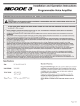
WIRING DIAGRAM
11 OHM
SPEAKER
#2
11 OHM
SPEAKER
#1
RADIO SPEAKER
TO TWO-WAY
AUX. ENABLE
INPUT
CONNECT
OR
DIMMER RHEOSTAT
OPTION OR +12VDC
3 AMP FUSE
(CUSTOMER
SUPPLIED)
VEHICLE
HORN
+12V
HORN
RELAY
TO HORN
BUTTON
CUT
WIRE
HERE
GREEN
VIOLET
RED
RED
BLACK
BLACK
BLUE
BLUE
BROWN
ORANGE
YELLOW
3
6
7
8
12
11
10
4
1
5
2
RED
BLACK
VIOLET
GREEN
8
1
3
4
GREY
WHITE
BLACK / WHITE
YELLOW
7
6
2
5
YELLOW
BLUE
BLUE
ORANGE
BROWN
SIREN
AMPLIFIER
20 AMP FUSE
(CUSTOMER
SUPPLIED)
CONTROL
HEAD
8 POSITION SIREN CONNECTOR
+ BATTERY
HORN
HORN/RING
BACKLIGHT
TX
RX
AUX. ENABLE
REMOTE GND.
RED
GRAY
WHITE
YELLOW
VIOLET
GREEN
BLK / WHT
BLACK
FUNCTION
COLOR
8
7
6
5
4
3
2
1
PIN
BLACK 9
BLUE
6
BROWN
7
YELLOW
8
ORANGE
9
VIOLET
10
GREEN
11
BLACK
12
RADIO
SPEAKER COM
+SPEAKER #1
+SPEAKER #2
RX
TX
REMOTE GND.
PIN
COLOR
FUNCTION
1
RED
BLACK
2
BLUE
3
RED4
BLACK
5
+ BATTERY
GROUND
RADIO
+ BATTERY
GROUND
12-POSITION INPUT HARNESS
12V
BATTERY
8-POSITION INPUT
CONNECTOR ASSEMBLY
P/N 46-0745687-00
SYSTEM DIAGRAM
12-POSITION INPUT
CONNECTOR ASSEMBLY
P/N 46-0745693-00
WS295HFS2
12V AMPLIFIER
ASSEMBLY
P/N 01-0862062-00
R
.......800to 1600 Hz.........12Cycles Per Min.
.......800to 1600 Hz........180Cycles Per Min.
. . 800 to 1600 Hz........800Cycles Per Min.
...Composite ....................Constant
....300Hz TO 10KHz±3db
...............1%MAX.
....24VRMS MAX.
.........50WATTS
..............+10db ±3db
.... ...................Radio Manual Button
... ..............................18Khz
SIREN / SQUARE WAVE
AUDIO / SINE WAVE
TONE SIRENFREQUENCY SWEEPRATE
WAIL
YELP
PIERCER™
AIR HORN
Audio Bandwidth @25WATTS
Distors
ion 25 WATTS @1KHz
Output Voltage @15VDC @11OHMS
Output Power @15VDC @11OHMS
Radio Input Level @24 VRMS
SI-TEST®
Frequency
12.5 VDC ±20%
16 AMPSMAX.
20 AMPS
5.5 OHMS MIN
-30° C. TO +60
-40° C. TO +70
99% (NON CONDENSING)
INPUTVOLTAGE
INPUTCURRENT @15VDC @5.5 OHMS
INPUTFUSE
SPEAKER IMPEDANCE
OPERATING TEMPERATURE
STORAGE TEMPERATURE
HUMIDITY
SPECIFICATIONS
CUSTOMER SUPPLIED WIRE SIZE
12 AWG WIRE
10 AWG WIRE
8 AWG WIRE
WIREGAUGE
FOR 15.5 FEET OF WIRE
FOR 24.5 FEET OF WIRE
FOR 39 FEET OF WIRE
LENGTH OF WIRE
/