Page is loading ...

Page 1
Installation Guide:
ION™ Rear Spoiler Mounting Bracket
2020 Interceptor SUV
©2019 Whelen Engineering Company Inc.
Form No.14C84 (100219)
Automotive: Lightheads
For warranty information regarding this product, visit www.whelen.com/warranty
Warnings to Installers
Whelen’s emergency vehicle warning devices must be properly mounted and wired in order to be effective and safe. Read and follow all of Whelen’s
written instructions when installing or using this device. Emergency vehicles are often operated under high speed stressful conditions which must be
accounted for when installing all emergency warning devices. Controls should be placed within convenient reach of the operator so that they can operate
the system without taking their eyes off the roadway. Emergency warning devices can require high electrical voltages and/or currents. Properly protect
and use caution around live electrical connections.Grounding or shorting of electrical connections can cause high current arcing, which can cause
personal injury and/or vehicle damage, including fire. Many electronic devices used in emergency vehicles can create or be affected by electromagnetic
interference. Therefore, after installation of any electronic device it is necessary to test all electronic equipment simultaneously to insure that they operate
free of interference from other components within the vehicle. Never power emergency warning equipment from the same circuit or share the same
grounding circuit with radio communication equipment. All devices should be mounted in accordance with the manufacturer’s instructions and securely
fastened to vehicle elements of sufficient strength to withstand the forces applied to the device. Driver and/or passenger air bags (SRS) will affect the way
equipment should be mounted. This device should be mounted by permanent installation and within the zones specified by the vehicle manufacturer, if
any. Any device mounted in the deployment area of an air bag will damage or reduce the effectiveness of the air bag and may damage or dislodge the
device. Installer must be sure that this device, its mounting hardware and electrical supply wiring does not interfere with the air bag or the SRS wiring or
sensors. Mounting the unit inside the vehicle by a method other than permanent installation is not recommended as unit may become dislodged during
swerving; sudden braking or collision. Failure to follow instructions can result in personal injury. Whelen assumes no liability for any loss resulting from the
use of this warning device. PROPER INSTALLATION COMBINED WITH OPERATOR TRAINING IN THE PROPER USE OF EMERGENCY WARNING
DEVICES IS ESSENTIAL TO INSURE THE SAFETY OF EMERGENCY PERSONNEL AND THE PUBLIC.
Warnings to Users
Whelen’s emergency vehicle warning devices are intended to alert other operators and pedestrians to the presence and operation of emergency vehicles
and personnel. However, the use of this or any other Whelen emergency warning device does not guarantee that you will have the right-of-way or that
other drivers and pedestrians will properly heed an emergency warning signal. Never assume you have the right-of-way. It is your responsibility to proceed
safely before entering an intersection, driving against traffic, responding at a high rate of speed, or walking on or around traffic lanes. Emergency vehicle
warning devices should be tested on a daily basis to ensure that they operate properly. When in actual use, the operator must ensure that both visual and
audible warnings are not blocked by vehicle components (i.e.: open trunks or compartment doors), people, vehicles, or other obstructions. It is the user’s
responsibility to understand and obey all laws regarding emergency warning devices. The user should be familiar with all applicable laws and regulations
prior to the use of any emergency vehicle warning device. Whelen’s audible warning devices are designed to project sound in a forward direction away
from the vehicle occupants. However, because sustained periodic exposure to loud sounds can cause hearing loss, all audible warning devices should be
installed and operated in accordance with the standards established by the National Fire Protection Association.
Safety First
This document provides all the necessary information to allow your Whelen product to be properly and safely installed. Before beginning the installation
and/or operation of your new product, the installation technician and operator must read this manual completely. Important information is contained herein
that could prevent serious injury or damage.
• Proper installation of this product requires the installer to have a good understanding of automotive electronics, systems and procedures.
• Whelen Engineering requires the use of waterproof butt splices and/or connectors if that connector could be exposed to moisture.
• Any holes, either created or utilized by this product, should be made both air- and watertight using a sealant recommended by your vehicle
manufacturer.
• Failure to use specified installation parts and/or hardware will void the product warranty.
• If mounting this product requires drilling holes, the installer MUST be sure that no vehicle components or other vital parts could be damaged
by the drilling process. Check both sides of the mounting surface before drilling begins. Also de-burr the holes and remove any metal shards
or remnants. Install grommets into all wire passage holes.
• If this manual states that this product may be mounted with suction cups, magnets, tape or Velcro®, clean the mounting surface with a 50/50
mix of isopropyl alcohol and water and dry thoroughly.
• Do not install this product or route any wires in the deployment area of your air bag. Equipment mounted or located in the air bag deployment
area will damage or reduce the effectiveness of the air bag, or become a projectile that could cause serious personal injury or death. Refer to
your vehicle owner’s manual for the air bag deployment area. The User/Installer assumes full responsibility to determine proper mounting
location, based on providing ultimate safety to all passengers inside the vehicle.
• For this product to operate at optimum efficiency, a good electrical connection to chassis ground must be made. The recommended
procedure requires the product ground wire to be connected directly to the NEGATIVE (-) battery post (this does not include products that use
cigar power cords).
• If this product uses a remote device for activation or control, make sure that this device is located in an area that allows both the vehicle and
the device to be operated safely in any driving condition.
• Do not attempt to activate or control this device in a hazardous driving situation.
• This product contains either strobe light(s), halogen light(s), high-intensity LEDs or a combination of these lights. Do not stare directly into
these lights. Momentary blindness and/or eye damage could result.
• Use only soap and water to clean the outer lens. Use of other chemicals could result in premature lens cracking (crazing) and discoloration.
Lenses in this condition have significantly reduced effectiveness and should be replaced immediately. Inspect and operate this product
regularly to confirm its proper operation and mounting condition. Do not use a pressure washer to clean this product.
• It is recommended that these instructions be stored in a safe place and referred to when performing maintenance and/or reinstallation of this
product.
• FAILURE TO FOLLOW THESE SAFETY PRECAUTIONS AND INSTRUCTIONS COULD RESULT IN DAMAGE TO THE PRODUCT OR VEHICLE
AND/OR SERIOUS INJURY TO YOU AND YOUR PASSENGERS!
51 Winthrop Road
Chester, Connecticut 06412-0684
Phone: (860) 526-9504
Internet: www.whelen.com
Sales e-mail: autosale@whelen.com
Customer Service e-mail: [email protected]
®
ENGINEERING COMPANY INC.

Page 2
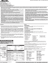
IMPORTANT! The lightbar should be a
minimum of 16" from any radio antennas!
2020 Ford Interceptor SUV:
1. Measure 15 inches from the center of
the rear visor on both sides and
center each bracket at this point. With
each bracket in the exact mounting
location, clearly mark the mounting
hole locations onto the spoiler then
remove the brackets.
2. Drill pilot holes for the four mounting
holes using a 7/64 drill bit and drill a
7/16 wire access hole (Fig. 2).
3. Following factory guidelines, remove the spoiler from the vehicle. Drill the wire access holes (Fig. 2) and install the wires on both lights into the spoiler as shown.
Make sure the lighthead wires with the connectors extend out of the wire holes just enough to connect to the lightheads.
4. Mount the brackets to the spoiler with the supplied 6 X 1/2 Phillips Pan Head Sheet Metal Screws. Repeat for the opposite side of the vehicle and then reinstall
the spoiler to the vehicle following factory specifications (see below).
5. Extend the wires to power and follow the lighthead instructions for fusing. It is suggested that you follow the vehicles factory wiring harness whenever possible.
IMPORTANT! Installation of any after-market equipment onto the rear spoiler of the Ford
Interceptor SUV requires the upfitter/installer to follow specific factory recommended
procedures and guidelines. Ford Motor Company has created a video specifically
designed to demonstrate the techniques necessary for a proper and safe installation. This
video should be viewed prior to beginning the installation.
The components and materials needed to achieve this are found in Ford Spoiler Repair
Kit (Contact Whelen Customer Support for kit part number). The kit with video should
provide the necessary information the upfitter/installer needs.
(FordBBAS.com) Look under: Public Police Modifiers Guides
• Removal of the spoiler usually causes one or more retainer clips to break. Additionally,
the integrity of the various seals may also become compromised by the spoiler removal
procedure and must be replaced.
• The foam seal around the Liftgate Tower may not be re-used and must be replaced
(Fig. 1). The repair kit includes a replacement foam seal as well as the supplemental
seal to be installed as well. As shown in the video, remove any remnants of the existing
foam seal.
Position the supplemental foam seal under the wiring and wash line and adhere
directly to the spoiler. IMPORTANT: Apply a generous bead of Motorcraft TA-2
sealant or equivalent over the vehicle and lighthead wires and washer line. While
the sealant is still wet, install the Tower foam seal as shown in the video.
• Spoiler removal is likely to break or damage the spoiler retainer clips (Fig. 2).
Replace all the existing clips and their seals with those included in the repair
kit.
• Spoiler removal can potentially deform the liftgate retaining clip mounting
holes. These mounting holes must be carefully straightened using a flat faced
hammer (Fig. 3). Be sure that any raised distortions are hammered flush or
below the original surface before reinstalling the spoiler.
REAR WINDOW
R
E
AR
V
I
S
O
R
MOUNTING LIGHTHEADMOUNTING BRACKET
Fig. 1
IMPORTANT! The membrane
must always face downwards.
NEVER obstruct or remove
this membrane regardless of
mounting style.
6 x 5/16 PWH
Plastite Screw
6 X 1/2 Phillips Pan Head
Sheet Metal Screws
Drill the wire hole under the mounting bracket
so it doesn't show when the bracket is mounted
/