Page is loading ...

Page 1
©2010 Whelen Engineering Company Inc.
Form No.14439 (121010)
Automotive: Lightbars
For warranty information regarding this product, visit www.whelen.com/warranty
• Proper installation of this product requires the installer to have a good understanding of automotive electronics, systems and procedures.
• Whelen Engineering requires the use of waterproof butt splices and/or connectors if that connector could be exposed to moisture.
• Any holes, either created or utilized by this product, should be made both air- and watertight using a sealant recommended by your vehicle
manufacturer.
• Failure to use specified installation parts and/or hardware will void the product warranty.
• If mounting this product requires drilling holes, the installer MUST be sure that no vehicle components or other vital parts could be damaged
by the drilling process. Check both sides of the mounting surface before drilling begins. Also de-burr the holes and remove any metal shards
or remnants. Install grommets into all wire passage holes.
• If this manual states that this product may be mounted with suction cups, magnets, tape or Velcro®, clean the mounting surface with a 50/50
mix of isopropyl alcohol and water and dry thoroughly.
• Do not install this product or route any wires in the deployment area of your air bag. Equipment mounted or located in the air bag deployment
area will damage or reduce the effectiveness of the air bag, or become a projectile that could cause serious personal injury or death. Refer to
your vehicle owner’s manual for the air bag deployment area. The User/Installer assumes full responsibility to determine proper mounting
location, based on providing ultimate safety to all passengers inside the vehicle.
• For this product to operate at optimum efficiency, a good electrical connection to chassis ground must be made. The recommended
procedure requires the product ground wire to be connected directly to the NEGATIVE (-) battery post (this does not include products that use
cigar power cords).
• If this product uses a remote device for activation or control, make sure that this device is located in an area that allows both the vehicle and
the device to be operated safely in any driving condition.
• Do not attempt to activate or control this device in a hazardous driving situation.
• This product contains either strobe light(s), halogen light(s), high-intensity LEDs or a combination of these lights. Do not stare directly into
these lights. Momentary blindness and/or eye damage could result.
• Use only soap and water to clean the outer lens. Use of other chemicals could result in premature lens cracking (crazing) and discoloration.
Lenses in this condition have significantly reduced effectiveness and should be replaced immediately. Inspect and operate this product
regularly to confirm its proper operation and mounting condition. Do not use a pressure washer to clean this product.
• It is recommended that these instructions be stored in a safe place and referred to when performing maintenance and/or reinstallation of this
product.
• FAILURE TO FOLLOW THESE SAFETY PRECAUTIONS AND INSTRUCTIONS COULD RESULT IN DAMAGE TO THE PRODUCT OR VEHICLE
AND/OR SERIOUS INJURY TO YOU AND YOUR PASSENGERS!
Warnings to Installers
Whelen’s emergency vehicle warning devices must be properly mounted and wired in order to be effective and safe. Read and follow all of Whelen’s written
instructions when installing or using this device. Emergency vehicles are often operated under high speed stressful conditions which must be accounted for
when installing all emergency warning devices. Controls should be placed within convenient reach of the operator so that they can operate the system without
taking their eyes off the roadway. Emergency warning devices can require high electrical voltages and/or currents. Properly protect and use caution around
live electrical connections.Grounding or shorting of electrical connections can cause high current arcing, which can cause personal injury and/or vehicle
damage, including fire. Many electronic devices used in emergency vehicles can create or be affected by electromagnetic interference. Therefore, after
installation of any electronic device it is necessary to test all electronic equipment simultaneously to insure that they operate free of interference from other
components within the vehicle. Never power emergency warning equipment from the same circuit or share the same grounding circuit with radio
communication equipment. All devices should be mounted in accordance with the manufacturer’s instructions and securely fastened to vehicle elements of
sufficient strength to withstand the forces applied to the device. Driver and/or passenger air bags (SRS) will affect the way equipment should be mounted. This
device should be mounted by permanent installation and within the zones specified by the vehicle manufacturer, if any. Any device mounted in the deployment
area of an air bag will damage or reduce the effectiveness of the air bag and may damage or dislodge the device. Installer must be sure that this device, its
mounting hardware and electrical supply wiring does not interfere with the air bag or the SRS wiring or sensors. Mounting the unit inside the vehicle by a
method other than permanent installation is not recommended as unit may become dislodged during swerving; sudden braking or collision. Failure to follow
instructions can result in personal injury. Whelen assumes no liability for any loss resulting from the use of this warning device. PROPER INSTALLATION
COMBINED WITH OPERATOR TRAINING IN THE PROPER USE OF EMERGENCY WARNING DEVICES IS ESSENTIAL TO INSURE THE SAFETY OF
EMERGENCY PERSONNEL AND THE PUBLIC.
Warnings to Users
Whelen’s emergency vehicle warning devices are intended to alert other operators and pedestrians to the presence and operation of emergency vehicles and
personnel. However, the use of this or any other Whelen emergency warning device does not guarantee that you will have the right-of-way or that other
drivers and pedestrians will properly heed an emergency warning signal. Never assume you have the right-of-way. It is your responsibility to proceed safely
before entering an intersection, driving against traffic, responding at a high rate of speed, or walking on or around traffic lanes. Emergency vehicle warning
devices should be tested on a daily basis to ensure that they operate properly. When in actual use, the operator must ensure that both visual and audible
warnings are not blocked by vehicle components (i.e.: open trunks or compartment doors), people, vehicles, or other obstructions. It is the user’s responsibility
to understand and obey all laws regarding emergency warning devices. The user should be familiar with all applicable laws and regulations prior to the use of
any emergency vehicle warning device. Whelen’s audible warning devices are designed to project sound in a forward direction away from the vehicle
occupants. However, because sustained periodic exposure to loud sounds can cause hearing loss, all audible warning devices should be installed and
operated in accordance with the standards established by the National Fire Protection Association.
Safety First
This document provides all the necessary information to allow your Whelen product to be properly and safely installed. Before beginning the installation and/or
operation of your new product, the installation technician and operator must read this manual completely. Important information is contained herein that could
prevent serious injury or damage.
WARNING: This product can expose you to chemicals including Methylene Chloride which is known to the State of California to cause cancer, and
Bisphenol A, which is known to the State of California to cause birth defects or other reproductive harm. For more information go to
www.P65Warnings.ca.gov.
Installation Guide:
Outer Edge® Lightbar
2008 - 2011 Chevy Tahoe
51 Winthrop Road
Chester, Connecticut 06412-0684
Phone: (860) 526-9504
Internet: www.whelen.com
Sales e-mail: autosale@whelen.com
Customer Service e-mail: [email protected]
®
ENGINEERING COMPANY INC.

Page 2
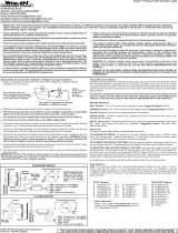
Wire Color Function
White/Violet Scan-Lock™
Grey (Connects to other Sync wires) SYNC
Black (12V) or Black/White (24V) To Ground
LED Color
Red/Wht (two-color split models)
Wht/Red (single-color split models)
or
or
Split Lighthead Operation:
PHASE 1
LEFT
RIGHT
side lights up and
with side.alternates
PHASE 2
RIGHT
LEFT
side lights up and
with side.alternates
PHASE 3
BOTH sides flash together
(ON-OFF-ON).
PHASE 4
BOTH sides flash together
(OFF-ON-OFF).
Phases3&4arevisually indistinguishable.
ON
ON
OFF
OFF
ONOFF
ON OFF
ON
ON
OFF
OFF
ONON
OFF
OFF
ONON
OFF
OFF
ON
ON
OFF
ON
ON
OFF
47. ModuFlash™
48. ModuFlash™
64. ActionScan™
49. DoubleFlash 120
50. DoubleFlash 120
51. PingPong™ 120
52. PingPong 120
53. TripleFlash™ 75
54. TripleFlash 75
55. TripleFlash 120
56. TripleFlash 120
57. SigAlert Cal.™
58. SigAlert Cal.
59. Action SF 60/120
60. Action SF 60/120
61. Action SF60/TF120
62. Action SF60/TF120
63. CalScan™
65. SteadyFlash 60
66. SteadyFlash 75
67. SteadyFlash 90
68. SteadyFlash 120
69. Steady & Steady
LINZ6™
SingleFlash 120
SingleFlash 300
DoubleFlash 150
ComAlert 150
ActionFlash™1
ActionFlash 2
ModuFlash™
.ActionScan™
Steady
17.
18.
19.
20.
21.
22.
23.
24
25.
Phase 1 flashes with Phase 1simultaneously
Phase 2 flashes with 2
1 with 2
simultaneously
alternates
Phase
Phase Phase
Phase Operation
Lamp Driver
RED
BLK
GRN
WHT
- Power
- Ground
- SYNC
- Scan-Lock
(FUSE @ 3A)
(Connect to other Sync wires)
(FUSE @ 1A)
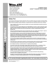
VERTEX™
Flash Patterns:
BOLDNOTE: = California Title XIII Compliant Pattern = SYNC PatternItalic
1.SignalAlert™75
2.SignalAlert75
3.SignalAlert75
4.SignalAlert75
5.CometFlash®75
6.CometFlash75
7.CometFlash75
8.CometFlash75
17.ComAlert™75
18.ComAlert75
19.ComAlert75
20.ComAlert75
21.LongBurst™75
22.LongBurst75
23.LongBurst75
9.DoubleFlash75
10.DoubleFlash75
11.DoubleFlash75
12.DoubleFlash75
13.SingleFlash75
14.SingleFlash75
15.SingleFlash75
16.SingleFlash75
Phase 1
P2
P3
P4
P1
P2
P3
P4
Phase 1
P2
P3
P4
P1
P2
P3
P1
P2
P3
P4
P1
P2
P3
P4
hase
hase
hase
hase
hase
hase
hase
hase
hase
hase
hase
hase
hase
hase
hase
hase
hase
hase
hase
hase
hase
ALT
SIM
ALT/SIM
ALT
SIM
ALT
SIM
ALT
SIM
ALT
SIM
ALT
SIM
ALT
SIM
ALT
SIM
ALT/SIM
24.LongBurst75
29.SSNF75
30.SSNF75
25.PingPong™75
26.PingPong75
27.PingPong75
28.PingPong75
31.SingleFlash 60
32.SingleFlash 60
SingleFlash
SingleFlash 0
35.SingleFlash 120
36.SingleFlash 120
SingleFlash 300
38.SingleFlash 300
DoubleFlash 150
40.DoubleFlash 150
41.ComAlert™ 150
42.ComAlert™ 150
43.ActionFlash™ 50
44.ActionFlash™ 50
45.ActionFlash™ 150
46.ActionFlash™ 150
33. 90
34. 9
37.
39.
P4
P1
P2
P1
P2
P3
P4
ALT
SIM
ALT
SIM
ALT
SIM
ALT
SIM
ALT
SIM
ALT
SIM
ALT
SIM
ALT
SIM
hase
hase
hase
hase
hase
hase
hase
1. SignalAlert™75
2.
3.
4.
5.
6.
7.
8.
SignalAlert 75
CometFlash®75
CometFlash 75
DoubleFlash 75
DoubleFlash 75
SingleFlash 75
SingleFlash 75
SYNC Patterns
P1hase
2
1
2
1
2
1
2
Phase
Phase
Phase
Phase
Phase
Phase
Phase
ComAlert™
ComAlert
LongBurst™
LongBurst
PingPong™
PingPong
9.
10.
11.
12.
13.
14.
15.
16.
SingleFlash 60
SingleFlash 90
Non-SYNC Patterns
1
2
1
2
1
2
Phase
Phase
Phase
Phase
Phase
Phase
To +VBAT
(Fuse@3amps)
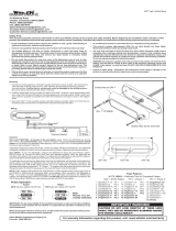
IMPORTANT! The lightbar should be a minimum of 16" from radio antennas!
Installation:
1. First, place the lightbar onto the mounting
location. The trimmed edge of the lightbar
should be flush with the bottom edge and
each outer edge of the "D" Pillar (Fig. 1).
2. Mark off and drill a 3/4” wire entry hole into
the "D" pillar using the measurements shown
(Fig. 2). Be very careful not to damage any
components behind the “D” Pillar.
Measure 2-1/4” from the leading edge and 4”
from the bottom edge of the “D” Pillar. The
wire entry hole will be located beneath the
bottom pod of the lightbar.
3. Remove the 2 screws holding on the taillight
(which overlaps the “D” Pillar) and pull the
taillight out.
4. Install the wiring and make all the wiring
connections (See wiring diagrams) then
reinstall the taillight.
Mounting the housings:
1. Place the lightbar onto its mounting location
on the vehicle to be sure the lightheads have
a sufficient service loop for lighthead
replacement or service. Once mounted, the
housing is not easily removed.
2. Using isopropyl alcohol (70%), clean the vehicle where it will come in contact
with the mounting tape then prime those areas with the supplied 3M Keel
Primer. Ready the leaders on the pre applied tape. Be sure the leaders are
protruding from under the housing so that you can pull the tape backing off
once the housing is in place.
3. There is a driver and passenger side housing. Be sure to mount them on
the correct sides. Firmly hold the lightbar onto its final mounting position.
While pressing the whole housing against the “D” Pillar, (being very careful not
to move the housing) slowly remove the tape backing from the top and leading
edge of the housing and then from the rear.
4. With the tape backing removed, press the housing firmly against the mounting
surface where the tape is, to secure it.
WARNING! The adhesive used in this procedure is fully bonded after 72
hours @ 70°F (21°C). During this period, do not expose the lights to any
unnecessary force, such as a high-pressure car wash.
IMPORTANT! It is the responsibility of the installation technician to make sure
that the installation and operation of this product will not interfere with or
compromise the operation or efficiency of any vehicle equipment!
WARNING! All customer supplied wires that connect to the positive terminal
of the battery must be sized to supply at least 125% of the maximum operating
current and
FUSED at the battery to carry that load. DO NOT USE CIRCUIT
BREAKERS WITH THIS PRODUCT
Operation:
Scan-Lock™
This feature allows you to program a selected flash pattern into a lighthead. The
lighthead must be activated to use Scanlock. The Scanlock™ wire is WHITE/VIOLET
on the LINZ6™ and WHITE on the Vertex™.
To cycle forward through patterns apply power to the Scanlock wire for less than 1
second and release.
To cycle backward through patterns apply power to the Scanlock wire for over 1
second and release. When the desired pattern is displayed, allow it to run for more
than 5 seconds. The lighthead will now display this pattern when active.
To reset to the factory default pattern Turn off power. Apply power to the Scanlock
wire while turning power back on.
Sync
The SYNC wire is GREY on the LINZ6™ and GREEN on the Vertex™. For SYNC to
operate, you must connect the SYNC wires together. If you do not want to use the
sync feature, cap the sync wires.
To sync two lightheads, configure both lightheads to display the same Phase 1
pattern. With the power off, connect the SYNC wires from each lighthead
together. When the lightheads are activated, their patterns will be
synchronized. To configure lightheads to alternate their patterns, advance the
pattern of that lighthead to the Phase 2 mode of the current pattern. The same
concept applies to Phases 3 & 4.
CAUTION! DO NOT LOOK DIRECTLY AT THESE LED’S WHILE THEY ARE ON.
MOMENTARY BLINDNESS AND/OR EYE DAMAGE COULD RESULT!
IMPORTANT WARNING!
/