Whelen Engineering Company Inner Edge XLP Installation guide
- Type
- Installation guide

Page 1
©2013 Whelen Engineering Company Inc.
Form No.14675A (022813)
Installation Guide:
Inner Edge® XLP Interior Lightbar
5-Light (w/Take-Down) 6-Light (w/o Take-Down)
2013 - Ford: Explorer, Taurus, SUV Interceptor, F-150 - F-550
Dodge: Charger, RAM 1500, Durango
Chevrolet: Caprice, Tahoe, Suburban, Silverado and all Pickups
2014 - Chevrolet: Tahoe, Suburban, Silverado and all Pickups
51 Winthrop Road
Chester, Connecticut 06412-0684
Phone: (860) 526-9504
Fax: (860) 526-4078
Internet: www.whelen.com
Sales e-mail: [email protected]
Canadian Sales e-mail: [email protected]
Customer Service e-mail: [email protected]
Automotive: Lightbars
®
ENGINEERING COMPANY INC.
For warranty information regarding this product, visit www.whelen.com/warranty
Warnings to Installers
Whelen’s emergency vehicle warning devices must be properly mounted and wired in order to be effective and safe. Read and follow all of Whelen’s
written instructions when installing or using this device. Emergency vehicles are often operated under high speed stressful conditions which must be
accounted for when installing all emergency warning devices. Controls should be placed within convenient reach of the operator so that he can operate
the system without taking his eyes off the roadway. Emergency warning devices can require high electrical voltages and/or currents. Properly protect and
use caution around live electrical connections.Grounding or shorting of electrical connections can cause high current arcing, which can cause personal
injury and/or vehicle damage, including fire. Many electronic devices used in emergency vehicles can create or be affected by electromagnetic
interference. Therefore, after installation of any electronic device it is necessary to test all electronic equipment simultaneously to insure that they operate
free of interference from other components within the vehicle. Never power emergency warning equipment from the same circuit or share the same
grounding circuit with radio communication equipment. All devices should be mounted in accordance with the manufacturer’s instructions and securely
fastened to vehicle elements of sufficient strength to withstand the forces applied to the device. Driver and/or passenger air bags (SRS) will affect the way
equipment should be mounted. This device should be mounted by permanent installation and within the zones specified by the vehicle manufacturer, if
any. Any device mounted in the deployment area of an air bag will damage or reduce the effectiveness of the air bag and may damage or dislodge the
device. Installer must be sure that this device, its mounting hardware and electrical supply wiring does not interfere with the air bag or the SRS wiring or
sensors. Mounting the unit inside the vehicle by a method other than permanent installation is not recommended as unit may become dislodged during
swerving; sudden braking or collision. Failure to follow instructions can result in personal injury. Whelen assumes no liability for any loss resulting from the
use of this warning device. PROPER INSTALLATION COMBINED WITH OPERATOR TRAINING IN THE PROPER USE OF EMERGENCY WARNING
DEVICES IS ESSENTIAL TO INSURE THE SAFETY OF EMERGENCY PERSONNEL AND THE PUBLIC.
Warnings to Users
Whelen’s emergency vehicle warning devices are intended to alert other operators and pedestrians to the presence and operation of emergency vehicles
and personnel. However, the use of this or any other Whelen emergency warning device does not guarantee that you will have the right-of-way or that
other drivers and pedestrians will properly heed an emergency warning signal. Never assume you have the right-of-way. It is your responsibility to proceed
safely before entering an intersection, driving against traffic, responding at a high rate of speed, or walking on or around traffic lanes. Emergency vehicle
warning devices should be tested on a daily basis to ensure that they operate properly. When in actual use, the operator must ensure that both visual and
audible warnings are not blocked by vehicle components (i.e.: open trunks or compartment doors), people, vehicles, or other obstructions. It is the user’s
responsibility to understand and obey all laws regarding emergency warning devices. The user should be familiar with all applicable laws and regulations
prior to the use of any emergency vehicle warning device. Whelen’s audible warning devices are designed to project sound in a forward direction away
from the vehicle occupants. However, because sustained periodic exposure to loud sounds can cause hearing loss, all audible warning devices should be
installed and operated in accordance with the standards established by the National Fire Protection Association.
Safety First
This document provides all the necessary information to allow your Whelen product to be properly and safely installed. Before beginning the installation
and/or operation of your new product, the installation technician and operator must read this manual completely. Important information is contained herein
that could prevent serious injury or damage.
• Proper installation of this product requires the installer to have a good understanding of automotive electronics, systems and procedures.
• Whelen Engineering recommends the use of waterproof butt splices and/or connectors if that connector could be exposed to moisture.
• Failure to use specified installation parts and/or hardware will void the product warranty.
• If mounting this product requires drilling holes, the installer MUST be sure that no vehicle components or other vital parts could be damaged
by the drilling process. Check both sides of the mounting surface before drilling begins. Also de-burr the holes and remove any metal shards
or remnants. Install grommets into all wire passage holes.
• If this manual states that this product may be mounted with suction cups, magnets, tape or Velcro®, clean the mounting surface with a 50/50
mix of isopropyl alcohol and water and dry thoroughly.
• Do not install this product or route any wires in the deployment area of your air bag. Equipment mounted or located in the air bag deployment
area will damage or reduce the effectiveness of the air bag, or become a projectile that could cause serious personal injury or death. Refer to
your vehicle owner’s manual for the air bag deployment area. The User/Installer assumes full responsibility to determine proper mounting
location, based on providing ultimate safety to all passengers inside the vehicle.
• For this product to operate at optimum efficiency, a good electrical connection to chassis ground must be made. The recommended
procedure requires the product ground wire to be connected directly to the NEGATIVE (-) battery post (this does not include products that use
cigar power cords).
• If this product uses a remote device for activation or control, make sure that this device is located in an area that allows both the vehicle and
the device to be operated safely in any driving condition.
• Do not attempt to activate or control this device in a hazardous driving situation.
• This product contains either strobe light(s), halogen light(s), high-intensity LEDs or a combination of these lights. Do not stare directly into
these lights. Momentary blindness and/or eye damage could result.
• Use only soap and water to clean the outer lens. Use of other chemicals could result in premature lens cracking (crazing) and discoloration.
Lenses in this condition have significantly reduced effectiveness and should be replaced immediately. Inspect and operate this product
regularly to confirm its proper operation and mounting condition. Do not use a pressure washer to clean this product.
• It is recommended that these instructions be stored in a safe place and referred to when performing maintenance and/or reinstallation of this
product.
• FAILURE TO FOLLOW THESE SAFETY PRECAUTIONS AND INSTRUCTIONS COULD RESULT IN DAMAGE TO THE PRODUCT OR VEHICLE
AND/OR SERIOUS INJURY TO YOU AND YOUR PASSENGERS!

Page 2
10 X 1" PHILLIPS
PAN HD SHEET
METAL SCREW
(type A) (QTY 1)
#8-32 x 3/8 TORX HD
SCREW (QTY 2)
VISOR
SWIVEL
BRACKET
VISOR CLIP BRACKET
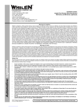
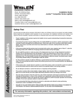
Fig. 2
SHEET METAL
HEADLINER
VISOR CLIP MOUNTING
BRACKET
SHEET
METAL
ROOF
RUBBER SEAL
Lightbar
Side View
WI
N
DS
H
IE
L
D
Side View
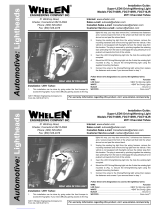
IMPORTANT! The lightbar should be a minimum of 16" from radio antennas!
When routing wires, choose a path that will keep wires away from excessive
heat or any vehicle equipment that could damage the wires.
Installation / Standard:
1. Loosen (do not remove) the three screws securing the passenger-side visor
swivel bracket to the vehicle.
2. Remove screws securing vehicles visor clip and remove clip and hardware.
3. Secure the bracket to the Inner Edge housing using hardware provided (Fig. 1).
4. Position the keyed opening of the mounting bracket directly under the location of
the visor clip removed in step 2 and remount the visor clip in its original location
using the original hardware (Fig. 1).
5. Firmly tighten any hardware loosened in this procedure.
6. Repeat this procedure for the driver-side assembly.
7. When properly mounted, the rubber seal will be in full contact with the vehicle
windshield and roof. This is to prevent light output from entering the passenger
compartment. When this has been achieved, tighten mounting hardware firmly.
8. Route the lightbar cable down the vehicle A-pillar to your control head. Make all
wiring connections using the information in the wiring diagram.
Installation / Caprice:
1. Secure
the mounting
bracket to the
Inner Edge housing
using the two
#8 - 32 X 3/8 TORX HEAD
SCREWS provided (Fig. 2).
2. Loosen (do not remove) the screws securing the passenger-side visor swivel
bracket to the vehicle.
3. Slide the outside end of the mounting bracket under the visor swivel bracket (Fig.
2). At the same time slip the rectangular hole in the other end of the mounting
bracket over the visor clip bracket. With the mounting bracket in position retighten
the visor swivel bracket hardware.
4. Using the screw hole in the mounting bracket as a guide, drill a pilot hole into the
sheet metal behind the headliner and secure other side of mounting bracket using
the supplied #10 X 1” PHILLIPS PAN HEAD SHEET METAL SCREW.
5. Repeat this procedure for the driver-side assembly.
6. When properly mounted, the rubber seal will be in full contact with the vehicle
windshield and roof. This is to prevent light from entering the passenger
compartment. When this has been achieved, tighten all mounting hardware firmly
to maintain contact.
7. Route the lightbar cable down the vehicle A-pillar to your control head and make
all wiring connections using the information in the wiring diagram.
Wiring:
WARNING! All customer supplied wires that connect to the positive terminal of
the battery must be sized to supply at least 125% of the maximum operating
current and FUSED at the battery to carry that load. DO NOT USE CIRCUIT
BREAKERS WITH THIS PRODUCT!
Operation:
8-conductor cable. All functions listed here may not be present in all lightbars.
WHITE/GREEN - Scan-Lock™
The WHT/GRN wire allows you to choose from a variety of flash patterns. A
light must be activated to change the pattern.
TO CYCLE THROUGH ALL PATTERNS: To cycle forward apply +12 VDC to the
WHT/GRN wire for less than 1 second and release. To cycle backward apply +12
VDC to the WHT/GRN wire for more than 1 second and release.
TO SET A PATTERN AS DEFAULT: When the pattern is displayed, allow it to run for
more than 5 seconds. The lighthead will now display this pattern when active.
TO RESET TO THE FACTORY DEFAULT PATTERN: Turn off power and apply +12
VDC to the WHT/GRN wire while turning power on.
A normally open momentary switch is best suited for Scan-Lock operation.
BLUE: Flash 1
Apply +12 VDC to the BLUE wire to activate the warning lights. Fuse wire @ 1 Amp.
BROWN: Hi/Low Power
This feature allows you to run the lightbar in low power for night time use. Fuse wire
@ 1 Amp. A single pole / single throw switch can be used to control Hi/Low power.
To activate Low power: Apply +12 VDC to the BRN wire. To restore regular
power: Remove the BRN wire from +12 VDC.
WHITE/BLACK: Take-Downs
Apply +12 VDC to the WHT/BLK wire to activate the take-downs. Fuse this wire @ 1
Amp. 5 light models only.
WHITE/ORANGE: Flashing Take-Down
Apply +12VDC to the WHT/ORG wire to activate flashing take-down mode. Fuse this
wire @ 1 Amp. Note: The WHT/BLK wire overrides this display. 5 light models.
ORANGE: California Steady
Apply +12 VDC to the ORG wire to activate lightheads using the California Steady
pattern table (next page). Refer to the following page for lighthead identification.
Fuse wire @ 1 Amp. NOTE: Due to firmware requirements, there are several
‘null’ patterns (no lighthead active) that precede Pattern 1. Repeated Scan-
Lock activations may be required before Pattern 1 selection is achieved.
Wiring Diagram
To +12VDC
(fuse ea. @ 1A
WHT/GRN
BROWN
BLUE
ORANGE
WHT/BLK
WHT/ORG
BLK
RED
Scan-Lock
Low Power
Flash 1
CA Steady
Take-Downs
Flashing T-D
Ground (-)
+12VDC
All Fuses & Switches Customer Supplied
Fuse
(5 Amp)
Wire Color Function
Momentary Switch
SPST Switch
SPST Switch
SPST Switch
SPST Switch
SPST Switch
BATTERY
Available Flash Patterns:
1. ActionScan™
2. SignalAlert™ 75 Alternating
3. SignalAlert™ 75 Multi.
4. CometFlash® 75 Alternating
5. CometFlash® 75 Multi.
6. DoubleFlash 75 Alternating
7. DoubleFlash 75 Multi.
8. SingleFlash 75 Alternating
9. SingleFlash 75 Multi.
10.LongBurst™ 75 Alternating
11. LongBurst™ 75 Multi.
12. SingleFlash 60 Alternating
13. SingleFlash 60 Multi.
14. SingleFlash 90 Alternating
15.SingleFlash 90 Multi.
16.SingleFlash 120 Alternating
17.SingleFlash 120 Multi.
18.‘SingleFlash 240 Alternating
19.SingleFlash 240 Multi.
20.DoubleFlash 120 Alternating
21.DoubleFlash120 Multi.
22.ActionFlash™ 75 Alt.
23.ActionFlash™ 75 Multi.
24.ActionFlash™ 150 Alt.
25.ActionFlash™ 150 Multi.
26.MicroBurst™ Alternating
27.MicroBurst™ Multi.
28.PingPong™ Alternating
29. PingPong™ Multi.
30.FlimFlam Alternating
31.FlimFlam Multi.
32.ModuFlash™ Alternating
33.ModuFlash™ Multi
34.Cylon 1
35.Cylon 2
36.Cylon Chaser
37.Eyeballs Sync
38.Eyeballs In/Out
39.2 Eyeballs In/Out
40.Eyeballs Crazy
Mounting
Bracket
ROOF
#8-32 x 3/8 Torx
Hd Screw (QTY 2)
RUBBER SEAL
Lightbar
Side View
Lightbar
Side View
Lightbar
Side View
WI
N
DS
H
IE
L
D
Fig. 1
HEADLINER
VISOR CLIP
side view
VISOR CLIP
side view
RETAINER
RETAINER
The & have a
retainer to hold the headliner to
the visor clip, which must be
removed before remounting
the visor clip.
Tahoe Silverado
NOTE: An Explorer mounting bracket is
shown here. The bracket for your vehicle
may be shaped differently but the basic
shape and mounting will be the same.
PASSENGER SIDE
Under visor
swivel bracket Under
visor clip
VISOR CLIP
side view

Page 3
DRIVER SIDE DOOR
Pry plastic
cover off
VISOR SWIVEL
BRACKET
WINDSHIELD
Remove screw
and visor clip
VISOR
CLIP
MOUNTING CLIP
(remove)
V
I
S
O
R
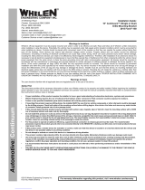
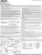
Fig. 1
WINDSHIELD
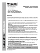
Installation 2013 Ford Fusion:
IMPORTANT AIR BAG WARNING! Do not install this product or route
any wires in the deployment area of your air bag. Equipment
mounted or located in the air bag deployment area will damage or
reduce the effectiveness of the air bag, or become a projectile that
could cause serious personal injury or death. Refer to your vehicle
owners manual for the air bag deployment area. The User/ Installer
assumes full responsibility to determine proper mounting location,
based on providing ultimate safety to all passengers.
IMPORTANT! The lightbar should be located a minimum of 16" from
any radio antennas!
Note: When routing the wires, it is important to choose a path that
will keep the wires away from excessive heat or any vehicle
equipment that could compromise the integrity of the wires (ex.
trunk lids, door jams, etc.)
Figures 1 thru 3 show the driver side of the interior of the vehicle, shown
looking up at the roof.
1. On the driver side visor swivel bracket, carefully pry the plastic cover
off of the front of the bracket (Fig. 1). The lightbar mounting bracket
will sit in the space that the cover occupied. NOTE: Pry the cover
off using two flat blade screwdrivers on each side to avoid
braking the cover. The cover will not be used here but should be
saved in case you wish to remove the lightbar in the future.
2. Remove the swivel bracket mounting clip (located under the cover
you removed in step 1) and lift the swivel bracket assembly out.
Install the supplied fastex grommet into the hole in the roof sheet
metal which the clip snapped into. Reinsert the swivel bracket
assembly (Figs. 1 & 2).
3. On the vehicle visor clip, remove the screw holding on the clip and
remove the clip. The supplied #8 X 1" sheet metal screw will replace
the screw you removed (Fig. 2).
4. Secure the mounting bracket to the lightbar and position the bracket
where it will mount on the vehicle (Figs. 3 & 4).
5. Secure the lightbar bracket to the swivel mount using the supplied 1/
4 X 1-1/4” Phillips Pan Head Sheet Metal Screw. This screw will
thread into the fastex grommet you installed in step 2 and the bracket
will sit where the cover was (Fig. 5).
6. Line the rectangular hole in the other end of the lightbar bracket, up
with the visor clip and install the visor clip over the lightbar bracket
using the supplied #8 X 1” Sheet Metal Screw (Fig. 3).
7. Make sure all mounting hardware is tightened firmly and repeat
procedure for the passenger side of the vehicle.
8. Extend the cables and connect to power. Refer to the lightbar manual
for wiring and fusing information.
Install Faston grommet
into existing hole in roof
that clip snapped into.
Fig. 2
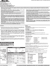
Fig. 4
When properly mounted, the rubber seal should be in full
contact with the vehicle windshield. The rear of the lightbar
should be in contact with the roof. This is to prevent light
from entering the passenger compartment. When this has
been achieved, tighten mounting hardware firmly to
maintain contact.
Mounting
Bracket
ROOF
#8-32 x 3/8 Torx Hd
Screw (QTY 2)
WI
N
DS
H
IE
L
D
RUBBER SEAL
Lightbar
Side View
Lightbar
Side View
Lightbar
Side View
Fig. 5
ROOF SHEET METAL
SCREW
GROMMET
HEADLINER
VISOR
SWIVEL
BRACKET
LT BAR BRACKET
MOUNTING TAB
Re-install visor clip over bracket
using supplied #8 X 1" sheet metal screw
Install into Faston grommet using
supplied 1/4 X 1-1/4" PPHSMS
Install into Faston grommet using
supplied 1/4 X 1-1/4" PPHSMS
Install into Faston grommet using
supplied 1/4 X 1-1/4" PPHSMS
MOUNTING
BRACKET
Fig. 3
CAUTION! DO NOT LOOK DIRECTLY AT THESE LED’S WHILE THEY ARE ON.
MOMENTARY BLINDNESS AND/OR EYE DAMAGE COULD RESULT!
IMPORTANT WARNING!
California Steady Pattern Table:
Active Lightheads
1. P1
2. P2
3. P3
4. P4
5. P5
6. P6 (6 Light models only)
PASSENGER SIDE (Top View)
PT-D P5 P4 P3 P2 P1
(or P6)

Page 4
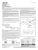
PART NUMBER KEY
01-0687417- _ _
YEAR/MAKE:
1 =
2 =
3 =
4 =
2013 TAURUS/INTERCEPTOR
2013 EXPLORER
2013 F150
2013 F250-550
2 = SUV INTERCEPTOR
2013 CHARGER6 =
2013 RAM 1500
2013 - DURANGO
2013 TAHOE/SUBURBAN/ ALL PICKUPS
2014 - TAHOE/SUBURBAN/ALL PICKUPS
7 =
8 =
B =
D =
9 =
C =
13 - CAPRICE PPV
2013 - FUSION
VERSION: 1 = 2 =5 LT W/TD 6 LT WO/TD
DODGE
2013 - RAM 1500
A
B
C
D
BASE, HOUSING PASS RAM 1500 INNER EDGE XLP BLACK
COVER, TOP PASS DODGE RAM 1500 INNER EDGE XLP BLACK
11-26E861-007
07-287518-023
11-36E862-007
BRACKET,VISOR MT PASS RAM 1500 INNER EDGE XLP BLACK
14-08228C-06D
SCREW, 8-32 X 3/8" PAN TORX HD ROLOK SS BLACK OXIDE
1
1
1
4
E15-081416-160
SCREW, 8 X 1 PPHSMS
2
ITEM PART NUMBER DESCRIPTION
QTY
NOT SHOWN
01-0687417-7_ FINAL, INNER EDGE XLP, 5/6 LIGHT
NOT SHOWN
2013 - DURANGO
11-26F187-007
07-287616-023
11-36F186-007
COVER, TOP PASS DODGE DURANGO INNER EDGE XLP BLACK
BASE, HOUSING PASS 13 DURANGO INNER EDGE XLP BLACK
BRACKET, VISOR MT PASS DURANGO INNER EDGE XLP BLACK
14-08228C-06D
SCREW, 8-32 X 3/8" PAN TORX HD ROLOK SS BLACK OXIDE
1
1
1
A
B
C
4D
ITEM PART NUMBER DESCRIPTION
QTY
01-0687417-8_ FINAL, INNER EDGE XLP, 5/6 LIGHT
2013 - CHARGER
11-26E265-007
07-287356-023
11-36E264-007
1
1
1
COVER, TOP PASS 12 CHARGER INNER EDGE XLP BLACK
BASE, HOUSING PASS 12 CHARGER INNER EDGE XLP BLACK
BRACKET, VISOR MT PASS CHARGER INNER EDGE XLP BLACK
A
B
C
14-08228C-06D4
SCREW, 8-32 X 3/8" PAN TORX HD ROLOK SS BLACK OXIDE
D
ITEM PART NUMBER DESCRIPTION
QTY
NOT SHOWN
01-0687417-6_ INNER EDGE XLP, 5/6 LIGHT
2013 - TAHOE/SUBURBAN/ALL PICKUPS
11-26E645-007
07-287449-023
11-36E644-007
1
1
1
COVER, TOP PASS 12 CHEVY TAHOE INNER EDGE XLP BLACK
BRACKET, VISOR MT PASS THOE INNER EDGE XLP BLACK
A
B
C
14-08228C-0604
SCREW, 8-32 X 3/8" PAN TORX HD ROLOK SS BLACK OXIDE
D
BASE, HOUSING, PASS 12 TAHOE INNER EDGE XLP BLACK
ITEM PART NUMBER DESCRIPTION
QTY
NOT SHOWN
01-0687417-B_ FINAL, INNER EDGE XLP, 5/6 LIGHT
NOT SHOWN
2014 - TAHOE/SUBURBAN/ALL PICKUPS
11-26F642-007
07-287726-023
11-36F641-007
COVER, TOP PASS 14 CHEVY TAHOE INNER EDGE XLP BLACK
BRACKET, VISOR MT PASS THOE INNER EDGE XLP BLACK
14-08228C-060
SCREW, 8-32 X 3/8" PAN TORX HD ROLOK SS BLACK OXIDE
BASE, HOUSING, PASS 14 TAHOE INNER EDGE XLP BLACK
1
1
1
A
B
C
4D
ITEM PART NUMBER DESCRIPTION
QTY
01-0687417-D_ FINAL, INNER EDGE XLP, 5/6 LIGHT
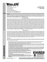
CHEVROLET
A
1
7
3
1514
18
16 17
13
2
10
B
2
01-0687417-_1
INNER EDGE XLP, LOW CURRENT 5 LT W/TD
14-040286-06D
SCREW, 4-40 X 3/8 PAN TORX HD ROLOK SS
14-08228C-06D
SCREW, 8-32 X 3/8" PAN TORX HD ROLOK SS BLK
39-1M17672-08
HSNG, PLUG 8 POS 18 AWG SL-156 W/ LOCK. RAMP
46-0743403-00
CABLE 9/C 18 GA TPR 20' SL-156 SCKTS ONE END
01-026E492-00
SUB ASSY, LC I/O INNER-EDGE XLP
46-076E495-00
HARNESS PASSENGER INNER EDGE XLP
46-076E495-01
HARNESS DRIVER INNER EDGE XLP
01-026E488-31
SUB ASSY, TAKE DOWN WHITE INNER-EDGE XLP
01-026E488-10
SUB ASSY, WARNING AMB INNER-EDGE XLP
01-026E488-20
SUB ASSY, WARNING BLU INNER-EDGE XLP
01-026E488-30
SUB ASSY, WARNING WHT INNER-EDGE XLP
01-026E488-40
SUB ASSY, WARNING GRN INNER-EDGE XLP
01-026E488-50
SUB ASSY, WARNING RED INNER-EDGE XLP
2
4
1
1
1
1
A/R
A/R
A/R
A/R
A/R
01-0687417-_2
INNER EDGE XLP, LOW CURRENT 6 LT W/O TD
38-0546827-14
SEAL HSNG/WINDSHIELD 13.600" INNER EDGE XLP
1
2
4
1
1
1
1
1
A/R
A/R
A/R
A/R
A/R
1
SCREW, 4-40 X 1/4 PPHMS 410SS BLK PASSIVATE
14-040216-04H
12 12
2
3
ITEM PART NUMBER DESCRIPTION
QTY QTY
13
14
15
16
17
18
4
5
7
8
9
10
1
NOTE: There are Passenger and Driver specific
lightheads.NOTE:
NOTE: Mounting brackets and hardware not shown.
2013 - CAPRICE PPV
A
B
C
D
E
ITEM PART NUMBER DESCRIPTION
QTY
NOT SHOWN
01-0687417-9_
11-26E493-007
07-287419-023
11-36E494-007
COVER, TOP PASS 12 CAPRICE INNER EDGE XLP BLACK
BASE, HOUSING PASS 12 CAPRICE INNER EDGE XLP BLACK
BRACKET, VISOR MT PASS CAPRICE INNER EDGE XLP BLACK
FINAL, INNER EDGE XLP, 5/6 LIGHT
14-08228C-06D
15-10141B-162
SCREW, 8-32 X 3/8" PAN TORX HD ROLOK SS BLACK OXIDE
SCREW, 10 X 1" PPH SMS TYPE A SS BLACK OXIDE
1
1
1
2
1
FORD
2013 - TAURUS/INTERCEPTOR
11-36E485-007
07-287414-023
11-26E484-007
1
1
1
BASE, HOUSING PASS 12 TAURUS INNER EDGE XLP BLACK
COVER, TOP PASS 12 TAURUS INNER EDGE XLP BLACK
BRACKET, VISOR MT PASS TAURUS INNER EDGE XLP BLACK
A
B
C
14-08228C-06D4
SCREW, 8-32 X 3/8" PAN TORX HD ROLOK SS BLACK OXIDE
D
ITEM PART NUMBER DESCRIPTION
QTY
NOT SHOWN
01-0687417-1_ FINAL, INNER EDGE XLP, 5/6 LIGHT
2013 - F250-550
A
B
C
D4
1
1
1
SCREW, 8-32 X 3/8" PAN TORX HD ROLOK SS BLACK OXIDE
14-08228C-06D
BRACKET, VISOR MT PASS BLK F-250/350 INNER EDGE XLP
BASE, HOUSING PASS BLACK 13 F-250/350 INNER EDGE XLP
COVER, TOP PASS BLACK 2013 F-250/350 INNER EDGE XLP
11-36E848-007
07-287511-023
11-26E872-007
ITEM PART NUMBER DESCRIPTION
QTY
NOT SHOWN
01-0687417-4_ INNER EDGE XLP, 5/6 LIGHT
2013 - F150
A
B
C
D
1
1
1
4
11-26E830-007
07-287501-023
11-36E829-007
COVER, TOP PASS BLACK 13 FORD F-150 INNER EDGE XLP
BASE, HOUSING PASS BLK 13 FORD F-150 INNER EDGE XLP
BRACKET, VISOR MT PASS BLK 13 FORD F-150 INNER EDGE XLP
14-08228C-06D
SCREW, 8-32 X 3/8" PAN TORX HD ROLOK SS BLACK OXIDE
1
1
4
ITEM PART NUMBER DESCRIPTION
QTY
NOT SHOWN
01-0687417-3_ FINAL, INNER EDGE XLP, 5/6 LIGHT
2013 - EXPLORER/SUV INTERCEPTOR
11-26E299-007
07-287371-023
11-36E300-007
1
1
1
COVER, TOP PASS BLACK 13 FORD SUV INNER EDGE XLP
BASE, HOUSING PASS BLACK 13 FORD SUV INNER EDGE XLP
BRACKET, VISOR MT PASS BLK 13 FORD SUV INNER EDGE XLP
A
B
C
14-08228C-06D4
SCREW, 8-32 X 3/8" PAN TORX HD ROLOK SS BLACK OXIDE
D
ITEM PART NUMBER DESCRIPTION
QTY
NOT SHOWN
01-0687417-2_ FINAL, INNER EDGE XLP, 5/6 LIGHT
2013 - FUSION
A
B
C
D
E
F
ITEM PART NUMBER DESCRIPTION
QTY
NOT SHOWN
01-0687417-C_
11-26E890-007
07-287529-023
11-36E891-007
COVER, TOP PASS FORD FUSION DUO INNER EDGE XLP BLACK
BASE, HOUSING PASS 2013 FUSION INNER EDGE XLP BLACK
BRACKET, VISOR MT PASS FUSION INNER EDGE XLP BLACK
21-12081205-3
SCREW GROMMET, FASTEX # 212-240602-040101
15-131416-202
SCREW, 1/4 X 1 1/4 PPHSMS SS TYPE A
15-081416-160
SCREW, 8 X 1 PPHSMS
FINAL, INNER EDGE XLP, 5/6 LIGHT
1
1
1
1
1
1
-
 1
1
-
 2
2
-
 3
3
-
 4
4


Whelen Engineering Company Inner Edge XLP Installation guide
- Type
- Installation guide
Ask a question and I''ll find the answer in the document
Finding information in a document is now easier with AI
Related papers
-
 Whelen Engineering Company ION Installation guide
-
 Whelen Engineering Company M2 Series Installation guide
-
 Whelen Engineering Company M6 series Installation guide
-
 Whelen Engineering Company 10” Continuum Single Installation guide
-
 Whelen Engineering Company UPS64LXA Installation guide
-
 Whelen Engineering Company PCC10W1 Installation guide
-
 Whelen Engineering Company Inner Edge Interior Series Installation guide
-
 Whelen Engineering Company Super-LED FDCT10RR Installation guide
-
 Whelen Engineering Company 900 Series Installation guide
-
 Whelen Engineering Company Outer Edge Installation guide


Other documents
-
 Ultra-tow 40509 Owner's manual
-
Game Of Bricks 76904 User manual
-
 Whelen Engineering IONSMA Owner's manual
-
 Whelen IONBKT8 Installation guide
-
 Cell2 1516.6mm Kuiper Lightbar User manual
-
 Whelen Engineering JF0BAAAA Owner's manual
-
Cell2 02180151 User manual
-
 Whelen VTX609 Installation guide
-
 Whelen TADF6 Installation guide
-
 Whelen M9 Series (B/T/T, Back-Up, Turn Signal) Installation guide


