Page is loading ...

Page 1
©2011 Whelen Engineering Company Inc.
Form No.14515 (071411)
Automotive: Lightheads
Installation Guide:
Super-LED® Driving/Warning Light
Models FDCT10BR, FDCT10RR, FDCT10JR
2011 Chevrolet Tahoe
®
ENGINEERING COMPANY INC.
Internet: www.whelen.com
Sales e-mail: autosale@whelen.com
Canadian Sales e-mail: Canadiansales@whelen.com
Customer Service e-mail: custserv@whelen.com
For warranty information regarding this product, visit www.whelen.com/warranty
51 Winthrop Road,
Chester, Connecticut 06412-0684
Phone: (860) 526-9504
Fax: (860) 526-4078
Installation / 2011 Tahoe:
1. This installation can be done by going under the front bumper to
access the fog lights. If you have difficulty gaining access to the fog
lights this way, you may also remove the 3 christmas tree fasteners
and 2 screws toward the front of the wheel well that hold the wheel
shroud on and peel the shroud back.
2. Unplug the existing fog light from the wiring harness, remove the
mounting hardware and remove the fog light from the vehicle. If the
vehicle is not equipped with fog lights remove the rubber plug from
this location. The plug is removed by pinching together the retaining
clips protruding from the back to disengage the plug allowing it to be
pushed out towards the front of the vehicle.
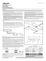
3. Insert the LED Driving/Warning light into the hole the existing light
occupied.
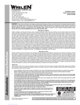
4. Mount the LED Driving/Warning light into the 2 slots the existing light
mounted to (Fig. 1). Secure the Driving/Warning light using the
supplied mounting hardware.
5. Connect the wires to the Driving/Warning light wiring then replace
the fasteners and screws if you removed them in step 1.
Follow these wire designations to connect the lighthead wires:
WIRE.............................................................................................Function
LED Color ..........................................................+VBAT for Warning Lights
WHITE ..................................................................+VBAT for Driving Lights
BLACK ....................................................................................... Ground (-)
WHT/VIO................................................................................. Scan-Lock™
©2011 Whelen Engineering Company Inc.
Form No.14515 (071411)
Automotive: Lightheads
Installation Guide:
Super-LED® Driving/Warning Light
Models FDCT10BR, FDCT10RR, FDCT10JR
2011 Chevrolet Tahoe
®
ENGINEERING COMPANY INC.
Internet: www.whelen.com
Sales e-mail: autosale@whelen.com
Canadian Sales e-mail: Canadiansales@whelen.com
Customer Service e-mail: custserv@whelen.com
For warranty information regarding this product, visit www.whelen.com/warranty
51 Winthrop Road,
Chester, Connecticut 06412-0684
Phone: (860) 526-9504
Fax: (860) 526-4078
Installation / 2011 Tahoe:
1. This installation can be done by going under the front bumper to
access the fog lights. If you have difficulty gaining access to the fog
lights this way, you may also remove the 3 christmas tree fasteners
and 2 screws toward the front of the wheel well that hold the wheel
shroud on and peel the shroud back.
2. Unplug the existing fog light from the wiring harness, remove the
mounting hardware and remove the fog light from the vehicle. If the
vehicle is not equipped with fog lights remove the rubber plug from
this location. The plug is removed by pinching together the retaining
clips protruding from the back to disengage the plug allowing it to be
pushed out towards the front of the vehicle.
3. Insert the LED Driving/Warning light into the hole the existing light
occupied.
4. Mount the LED Driving/Warning light into the 2 slots the existing light
mounted to (Fig. 1). Secure the Driving/Warning light using the
supplied mounting hardware.
5. Connect the wires to the Driving/Warning light wiring then replace
the fasteners and screws if you removed them in step 1.
Follow these wire designations to connect the lighthead wires:
WIRE.............................................................................................Function
LED Color ..........................................................+VBAT for Warning Lights
WHITE ..................................................................+VBAT for Driving Lights
BLACK ....................................................................................... Ground (-)
WHT/VIO................................................................................. Scan-Lock™

Page 2
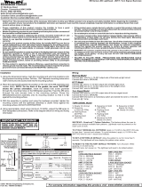
#10 FLATWASHER
MOUNTING
BRACKET
10-32 ELASTIC STOP NUT
Operation:
Warning Light Input - RED/WHT wire (RED/BLUE light) or BLUE wire (BLUE light)
or RED wire (RED light): Positive voltage for Warning Lights
Apply positive voltage to this wire to activate the warning lights. If this wire is
activated, the driving lights (White LEDs) will not operate.
Driving Light Input - WHITE Wire: Positive voltage for Driving Lights
Apply positive voltage to this wire to activate the driving lights. If the warning lights are
activated, this wire will not work. If this wire is activated and you engage the warning
lights, the driving lights cut out automatically .
Flash Pattern Selection (Scan-Lock™) - WHITE-VIOLET wire:
With the Warning Lights activated: TO CYCLE FORWARD TO THE NEXT
PATTERN, apply +VBAT to the WHT/VIO wire for less than 1 second and release. TO
CYCLE BACK TO THE PREVIOUS PATTERN, apply +VBAT to the WHT/VIO wire
for more than 1 second and release.
TO CHANGE THE DEFAULT PATTERN: When the desired pattern is displayed,
allow it to run for more than 5 seconds. The warning lights will now display this pattern
when initially activated.
TO RESTORE THE FACTORY DEFAULT PATTERN: With the power to the warning
lights off, apply +VBAT to the WHT/VIO wire. With the WHT/VIO wire still activated,
turn power to the warning lights on. The factory default pattern should now be
displayed.
Use a normally open momentary switch to control Scan-Lock™
WARNING! All customer
supplied wires that
connect to the positive
terminal of the battery
must be sized to supply
at least 125% of the
maximum operating
current and FUSED at
the battery to carry that
load. DO NOT USE
CIRCUIT BREAKERS
WITH THIS PRODUCT!
WARNING!It is the
responsibility of the
installation technician to
make sure that the
installation and
operation of this product will not interfere with or compromise the operation or
efficiency of any vehicle equipment!
Available Flash Patterns:
1. SignalAlert™ 75 ALT
2. SignalAlert™ 75 SIM
3. CometFlash® 75 ALT
4. CometFlash® 75 SIM
5. DoubleFlash 75 ALT
6. DoubleFlash 75 SIM
7. SingleFlash 75 ALT
8. SingleFlash 75 SIM
9. ComAlert™ 75 ALT
10. ComAlert™ 75 SIM
11. LongBurst™ 75 ALT
12. LongBurst™ 75 SIM
13. PingPong™ 75 ALT
14. PingPong™ 75 SIM
15. SSNF 75
16. SingleFlash 60 ALT
17. SingleFlash 60 SIM
18. SingleFlash 90 ALT
19. SingleFlash 90 SIM
20. SingleFlash 120 ALT
21. SingleFlash 120 SIM
22. SingleFlash 300 ALT
23. SingleFlash 300 SIM
24. DoubleFlash 150 ALT
25. DoubleFlash 150 SIM
26. ComAlert™ 150 ALT
27. ComAlert™ 150 SIM
28. ActionFlash™ 50 ALT
29. ActionFlash™ 50 SIM
30. ActionFlash™ 150 ALT
31. ActionFlash™ 150 SIM
32. ModuFlash™ ALT
33. ModuFlash™ SIM
34. DoubleFlash 120 ALT
35. DoubleFlash 120 SIM
36. PingPong™ 120 ALT
37. PingPong™ 120 SIM
38. TripleFlash™ 75 ALT
39. TripleFlash™ 75 SIM
40. TripleFlash™ 120 ALT
41. TripleFlash™ 120 SIM
42. SignalAlert™ CAL ALT
43. SignalAlert™ CAL SIM
44. ActionFlash™ SF60/120 ALT
45. ActionFlash™ SF60/120 SIM
46. ActionFlash™ SF120/TF75 ALT
47. ActionFlash™ SF120/TF75 SIM
48. CalScan™
49. ActionScan™
50. STEADY
ALT = Alternating: With a RED/BLUE light, RED will alternate with BLUE in the choosen pattern. With a RED or BLUE light, RED or BLUE will alternate from top to bottom in
the choosen pattern. SIM = Simultaneous: With a RED/BLUE light, both RED and BLUE will light up simultaneously in the choosen pattern. With an all RED or all BLUE light,
the whole light will light up RED or BLUE in the choosen pattern. BOLD TYPE = California Title 13 compliant.
CAUTION! DO NOT LOOK DIRECTLY AT THESE LED’S WHILE THEY ARE ON.
MOMENTARY BLINDNESS AND/OR EYE DAMAGE COULD RESULT!
IMPORTANT WARNING!
/