Page is loading ...

Page 1
©2002 Whelen Engineering Company Inc.
Form No.13657M (061410)
Automotive: Lightbars
For warranty information regarding this product, visit www.whelen.com/warranty
• Proper installation of this product requires the installer to have a good understanding of automotive electronics, systems and procedures.
• Whelen Engineering requires the use of waterproof butt splices and/or connectors if that connector could be exposed to moisture.
• Any holes, either created or utilized by this product, should be made both air- and watertight using a sealant recommended by your vehicle
manufacturer.
• Failure to use specified installation parts and/or hardware will void the product warranty.
• If mounting this product requires drilling holes, the installer MUST be sure that no vehicle components or other vital parts could be damaged
by the drilling process. Check both sides of the mounting surface before drilling begins. Also de-burr the holes and remove any metal shards
or remnants. Install grommets into all wire passage holes.
• If this manual states that this product may be mounted with suction cups, magnets, tape or Velcro®, clean the mounting surface with a 50/50
mix of isopropyl alcohol and water and dry thoroughly.
• Do not install this product or route any wires in the deployment area of your air bag. Equipment mounted or located in the air bag deployment
area will damage or reduce the effectiveness of the air bag, or become a projectile that could cause serious personal injury or death. Refer to
your vehicle owner’s manual for the air bag deployment area. The User/Installer assumes full responsibility to determine proper mounting
location, based on providing ultimate safety to all passengers inside the vehicle.
• For this product to operate at optimum efficiency, a good electrical connection to chassis ground must be made. The recommended
procedure requires the product ground wire to be connected directly to the NEGATIVE (-) battery post (this does not include products that use
cigar power cords).
• If this product uses a remote device for activation or control, make sure that this device is located in an area that allows both the vehicle and
the device to be operated safely in any driving condition.
• Do not attempt to activate or control this device in a hazardous driving situation.
• This product contains either strobe light(s), halogen light(s), high-intensity LEDs or a combination of these lights. Do not stare directly into
these lights. Momentary blindness and/or eye damage could result.
• Use only soap and water to clean the outer lens. Use of other chemicals could result in premature lens cracking (crazing) and discoloration.
Lenses in this condition have significantly reduced effectiveness and should be replaced immediately. Inspect and operate this product
regularly to confirm its proper operation and mounting condition. Do not use a pressure washer to clean this product.
• It is recommended that these instructions be stored in a safe place and referred to when performing maintenance and/or reinstallation of this
product.
• FAILURE TO FOLLOW THESE SAFETY PRECAUTIONS AND INSTRUCTIONS COULD RESULT IN DAMAGE TO THE PRODUCT OR VEHICLE
AND/OR SERIOUS INJURY TO YOU AND YOUR PASSENGERS!
Warnings to Installers
Whelen’s emergency vehicle warning devices must be properly mounted and wired in order to be effective and safe. Read and follow all of Whelen’s written
instructions when installing or using this device. Emergency vehicles are often operated under high speed stressful conditions which must be accounted for
when installing all emergency warning devices. Controls should be placed within convenient reach of the operator so that they can operate the system without
taking their eyes off the roadway. Emergency warning devices can require high electrical voltages and/or currents. Properly protect and use caution around
live electrical connections.Grounding or shorting of electrical connections can cause high current arcing, which can cause personal injury and/or vehicle
damage, including fire. Many electronic devices used in emergency vehicles can create or be affected by electromagnetic interference. Therefore, after
installation of any electronic device it is necessary to test all electronic equipment simultaneously to insure that they operate free of interference from other
components within the vehicle. Never power emergency warning equipment from the same circuit or share the same grounding circuit with radio
communication equipment. All devices should be mounted in accordance with the manufacturer’s instructions and securely fastened to vehicle elements of
sufficient strength to withstand the forces applied to the device. Driver and/or passenger air bags (SRS) will affect the way equipment should be mounted. This
device should be mounted by permanent installation and within the zones specified by the vehicle manufacturer, if any. Any device mounted in the deployment
area of an air bag will damage or reduce the effectiveness of the air bag and may damage or dislodge the device. Installer must be sure that this device, its
mounting hardware and electrical supply wiring does not interfere with the air bag or the SRS wiring or sensors. Mounting the unit inside the vehicle by a
method other than permanent installation is not recommended as unit may become dislodged during swerving; sudden braking or collision. Failure to follow
instructions can result in personal injury. Whelen assumes no liability for any loss resulting from the use of this warning device. PROPER INSTALLATION
COMBINED WITH OPERATOR TRAINING IN THE PROPER USE OF EMERGENCY WARNING DEVICES IS ESSENTIAL TO INSURE THE SAFETY OF
EMERGENCY PERSONNEL AND THE PUBLIC.
Warnings to Users
Whelen’s emergency vehicle warning devices are intended to alert other operators and pedestrians to the presence and operation of emergency vehicles and
personnel. However, the use of this or any other Whelen emergency warning device does not guarantee that you will have the right-of-way or that other
drivers and pedestrians will properly heed an emergency warning signal. Never assume you have the right-of-way. It is your responsibility to proceed safely
before entering an intersection, driving against traffic, responding at a high rate of speed, or walking on or around traffic lanes. Emergency vehicle warning
devices should be tested on a daily basis to ensure that they operate properly. When in actual use, the operator must ensure that both visual and audible
warnings are not blocked by vehicle components (i.e.: open trunks or compartment doors), people, vehicles, or other obstructions. It is the user’s responsibility
to understand and obey all laws regarding emergency warning devices. The user should be familiar with all applicable laws and regulations prior to the use of
any emergency vehicle warning device. Whelen’s audible warning devices are designed to project sound in a forward direction away from the vehicle
occupants. However, because sustained periodic exposure to loud sounds can cause hearing loss, all audible warning devices should be installed and
operated in accordance with the standards established by the National Fire Protection Association.
Safety First
This document provides all the necessary information to allow your Whelen product to be properly and safely installed. Before beginning the installation and/or
operation of your new product, the installation technician and operator must read this manual completely. Important information is contained herein that could
prevent serious injury or damage.
WARNING: This product can expose you to chemicals including Methylene Chloride which is known to the State of California to cause cancer, and
Bisphenol A, which is known to the State of California to cause birth defects or other reproductive harm. For more information go to
www.P65Warnings.ca.gov.
Installation Guide:
Edge® 9M Lightbar
51 Winthrop Road
Chester, Connecticut 06412-0684
Phone: (860) 526-9504
Internet: www.whelen.com
Sales e-mail: autosale@whelen.com
Customer Service e-mail: [email protected]
®
ENGINEERING COMPANY INC.

Page 2
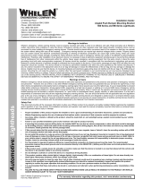
Insert foot into extrusion with locking plate
attached.
Twist mounting foot into
position
ANCHOR
PLATE
Loosely secure foot and locking plate.
Strap Mounting:
1. Locate the mounting foot, anchor plate and locking plate included with
your lightbar. If not already present, install the locking plate onto the
mounting foot. When properly positioned, this plate is centered from side-
to-side on the mounting foot.
2. Flip the lightbar upside-down to expose the bottom of the extrusion and
place the mounting foot onto the extrusion.
3. Rotate the mounting foot 90° in a counter-clockwise direction. Make sure
that the edges of the mounting foot swing into position under the extrusion
mounting lip. Install an anchor plate onto the extrusion in the same
manner.
4. Repeat this procedure for the remaining mounting foot and anchor plate
and return the lightbar to its right side-up position.
5. Position the lightbar onto the vehicle roof in the desired mounting location.
One often selected location is directly above the B-pillars. This area is the
strongest part of the roof. Refer to your lightbar manual for cable exit
location, to be sure that the lightbar is facing the proper direction.
6. Adjust the two mounting feet outwards so that they are as close to the
edge of the roof as possible. Both mounting feet must be in full contact
with the roof. Be sure that there is no less than 1/2” clearance between
roof and lightbar at their closest point. When the mounting feet are in their
proper position, lightly tighten the locking plate allen head set screws.
7. Return the lightbar to an upside-down position. Slide each anchor plate
outwards until it is fully engaged with its corresponding mounting foot.
With the mounting feet and anchor plates in their proper positions firmly
tighten all of the set screws (2 or 4 per side). Flip the lightbar right side-up
and return it to its mounting position.
8. Open both drivers side doors. In the area directly below the mounting
foot, pull the weatherstrip away from the vehicle so the area where the
mounting strap will be secured is exposed. Repeat for the other side.
9. Insert the mounting strap through the mounting foot. Be sure that the
strap fits flush against the area where it will be secured onto the vehicle.
IMPORTANT! The lightbar should be located a minimum of
16" from any radio antennas!
Permanent Mounting:
1. Locate the mounting foot and locking plate included with your
lightbar. If not already present, install the locking plate onto the
mounting foot. When properly positioned, this plate is centered from
side to side on the mounting foot.
2. Flip the lightbar upside-down to expose the bottom of the extrusion
and place the mounting foot onto the extrusion.
3. Rotate the mounting foot 90° in a counter-clockwise direction. Make
sure that the edges of the mounting foot swing into position under the
extrusion mounting lip.
4. Repeat this procedure for the remaining mounting foot and return the
lightbar to its right side-up position.
5. Position the lightbar onto the vehicle roof in the desired mounting
location. One often selected location is directly above the B-pillars.
This area is the strongest part of the roof. Refer to your lightbar
manual for cable exit location, to be sure that the lightbar is facing the
proper direction.
6. Adjust the two mounting feet outwards so that they are as close to
the edge of the roof as possible. Make sure that both mounting feet
are in full contact with the roof. Be sure that there is no less than 1/2”
clearance between the roof and the lightbar at their closest point.
When the mounting feet are in their proper position, lightly tighten the
locking plate allen head set screws.
7. Turn the lightbar upside down and firmly tighten all of the set screws
from step 6 (2 or 4 per side).
8. On the adjustable foot, use the hole in the pad as a guide to drill the
two holes into the mounting foot at the locations shown.
9. Place the lightbar in its final mounting position on the vehicle, mark
the mounting hole locations off onto the mounting surface, remove
the lightbar and drill the mounting holes.
10. Place the lightbar back onto the vehicle lined up with the mounting
holes and secure the mounting feet to the vehicle with the supplied
hardware.
Mounting
Pad
Adjustable
Mounting
Foot
Washer
Nut
Mounting
Foot
Base
Standard
Mounting
Foot
Mounting
Pad
Washer
Nut
Locking
Plate
Bolt
Bolt

Page 3
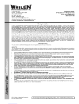
MOUNTING FOOT
TINNERMAN
NUT
FOOT
ANCHOR
PLATE
SET
SCREW
Plate slides into
lightbar extrusion
5" Mounting Foot
NUT
BOLT
SPLIT LOCK
WASHER
METAL SCREW
NOTE: The mounting straps are made to fit the contours of individual
vehicles. The strap
may look different. If your lightbar has a 5"
mounting foot, it will assemble differently than the standard
mounting foot. It also uses an extension to compensate for
the extra height. Follow these illustrations for assembly.
Mounting to the lightbar is the same.
shown here is for example only. The strap
for your vehicle
NOTE:
NOTE:
NOTE:
NOTE:
NOTE:
NOTE:
STRAP
SHEET
METAL
SCREWS
EXTENSION
VEHICLE ROOF
Locking
Plate
Mounting
Foot
Nut
Mounting
Pad
Adjustment
screws
Lock
Washer
Anchor
Plate
Tinnerman
Nut
Tinnerman
Nut
Anchor Plate
Locking
Plate
Mounting Strap
Mounting
Screw
Adjustable Foot
Model MKAJ
Standard Foot
Model MKEZ
Mounting
Strap
Mounting
Screw
Tension
Bolt
Tension
Bolt
Tighten screws
with torque wrench
set at 35 to 40 in/lbs
Model
MKAJ
Mounting
Foot
NOTE: Unless otherwise specified, the
lightbar mounting feet must be sitting as
close to the edge of the roof as possible.
Mounting feet must also be in full contact
with the roof and not be hanging off
the edge.
IMPORTANT: For strap mounted bars, be sure you have the right
sized lightbar for your vehicle. The lightbar should be about the same
width as the vehicle roof. If the lightbar is too large or small it will not mount properly to the vehicle and may shift or come loose during driving.
1/2" Minimum Clearance at Closest Point
Insert the tension bolt through the mounting strap and anchor plate, into
the tinnerman nut. Tighten slightly with a long-shafted, Phillips
screwdriver. Repeat procedure for passenger side.
10. If your mounting strap has mounting holes in the end of the strap, use
these holes as a template to drill appropriately sized pilot holes through
the strap and into the vehicle. Repeat for passenger side of the vehicle.
11. Firmly tighten the tension bolts to secure the lightbar to the vehicle.
NOTE: Model MKAJ is an adjustable mounting foot. On this model you
may loosen the screws on the rear of the foot and adjust the angle of the
lightbar. This feature can be used if the angle of the roof is not level with
the road. IMPORTANT: To adjust the leveling screws you must use a
torque wrench set at 35 to 40in./lbs.

Page 4
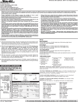
Routing your Edge® Lightbar Cable(s)
1. To protect the headliner from damage caused by drilling the
cable access hole through the vehicle roof, allow a 5” to 7”
distance between roof and headliner by lowering the
headliner before drilling.
2. Using a 1” hole saw, drill the cable access hole.
NOTE:There may be a roof support member that spans the
distance between the driver’s and passenger’s side. DO NOT
DRILL THROUGH THIS MEMBER! Adjust the location until
the hole can be drilled without contacting this support mem-
ber.
3. Use a round file to smooth and de-burr the edges of the hole.
4. Insert a 1” grommet (user supplied) into the cable access
hole.
5. Insert the cable(s) through the cable access hole into the
vehicle. Use RTV silicone to weatherproof the access hole
after the cable(s) are pulled completely into the vehicle.
6. Route the cable(s) one at a time to their respective
destinations (power cable to vehicle battery; control cable to
customer switch panel). It is left to the installation technician's
discretion to select a path for these cables that will both
protect the cables from possible damage and not interfere
with the operation of any other vehicle components or
equipment. Refer to the instructions included with your
switches for switch wiring information.
NOTE: The outer surfaces of this product may be cleaned
with mild soap and water. Use of any other chemicals may
void product warranty. Do not use a pressure washer.
Connecting the Cables
WARNING! All customer supplied wires that connect to the
positive terminal of the battery must be sized to supply at
least 125% of the maximum operating current and FUSED
at
the battery to carry that load. DO NOT USE CIRCUIT
BREAKERS WITH THIS PRODUCT!
Power Cable:
1. Follow the factory wiring harness through the firewall. It may
be necessary to drill a hole in the firewall. If so, be absolutely
sure that there are no components that could be damaged by
drilling. After the hole has been drilled, insert a grommet to
protect the cable.
2. Route the cable along the factory wiring harness towards the
battery. Install a 40 amp fuse block (customer supplied) on
the end of the RED wire in the power cable. Remove the fuse
from the fuse block before connecting any wires to the
battery.
3. Connect the fuse block to the POSITIVE (+) terminal on the
battery. There can not be more than two (2) feet of wire
between the fuse block and the battery. The wire between the
fuse block and the battery is “unprotected”, do not allow this
wire to come into contact with any other wires.
4. Connect the BLACK wire to the factory chassis ground
adjacent to the battery.
Control Cable:
Extend the control cable to your switch panel and make the
appropriate connections, using the information provided on pages
4 or 5, depending on which lightbar you have. When you apply
+12 VDC to a Control Cable wire, you activate its function. The
control cable connects to your control head or switch box and is
fused there. Typical fusing is 5 Amps.
LowPower / VIOLET :
The type of switch used is dependant on how the operator wishes
the Hi/Low feature to function:
Latching Mode: By applying +12 VDC voltage to the Violet wire
for less than 1 sec., the power supply is “latched” into low power
operation. The unit must be turned off and then back on to restore
normal, Hi power operation. (A Momentary Switch is Preferred)
Level Mode: Applying +12 VDC voltage to the Violet wire for
more than 1 sec. holds the power supply in low power mode until
voltage is removed. (A Toggle Switch is Preferred)
NOTE: The wire functions listed in this manual are the factory
default settings for a fully loaded lightbar. To find the correct
wire functions for the lightbar you ordered, refer to the
switch operations sheet included with your lightbar.
Troubleshooting:
Your lightbar should now be fully operational. If your lightbar is not
functioning properly, check the following:
• The positive wire (RED) is properly connected to the
battery, by way of the user supplied fuse block.
• A working fuse of the correct amperage (40 amp) is
installed in the fuse block.
• The ground wire (BLACK) is properly connected to the
factory ground.
If these connections are good, contact your Whelen
representative for further assistance.
DRILLING THE CABLE ACCESS HOLE
Drill cable access hole in appropriate area
for your lightbar (see note)
FRONT OF LIGHTBAR
For
cables exiting
the Driver-side
of the extrusion
lightbars
with
For
cables exiting
the Passenger-side
of the extrusion
lightbars
with

Page 5
ABAUX
Power Distribution Board
HALOGEN
FLASHER
A
HALOGEN
FLASHER
B
POS.4 POS.4
PS:A
PS:B
PS:C
Changing Flash Patterns Without a Scan-Lock™ Cable:
The 9M lightbar is capable of displaying a variety of flash patterns. These patterns can be changed using one of two methods. The first is through the optional Scan-Lock™
pattern cable. This allows you to change patterns from within the vehicle and is preferred by customers who want to be able to easily change their flash patterns if need arises.
For users who rarely or infrequently change patterns and do not require a Scan-Lock cable, you must partially disassemble the lightbar and change patterns manually.
WARNING: The strobe light power supply is a high voltage device. Do not remove strobe tubes or dismantle strobe light head assemblies in the system while it is in
operation. Wait 10 minutes after turning off power before starting work or any trouble shooting.
WARNING! THIS PROCEDURE REQUIRES THE LIGHTBAR TO BE ACTIVE WHILE IN A PARTIALLY DISASSEMBLED STATE. DO NOT TOUCH ANY LIGHTBAR
COMPONENTS EXCEPT FOR THOSE REFERENCED IN THIS PROCEDURE.
1. Notice where the cable enters the bottom of the extrusion. If it enters on the driver side, the Power Distribution Board will facethe rear of the vehicle. If it enters on the
passenger side, it will be facing the front of the vehicle.
2. Remove the endcap nearest to the cable entry. On the appropriate side (front or rear) of the lightbar, remove lenses and move lightheads away from the extrusion until
clear access to the Power Distribution Board has been gained. Be sure to record the exact position of each component to ensure proper re-assembly.
3. Changing Strobe Lighthead Patterns - Locate the 3-position connector. Each of the 3 sockets control pattern selection for each of the lightbar’s 3 strobe power supplies
(PS:A, PS:B and PS:C). In the default configuration, the corner strobes use PS: A, the inboard strobes use PS: B and the end strobes use PS: C. Activate the strobe lights
that are to receive the new flash pattern. Momentarily applying +12VDC to the appropriate socket will cycle that power supply’s current flash pattern to the next flash
pattern. Repeat this procedure until the desired pattern is displayed. Allowing this pattern to flash for a minimum of 5 seconds will make this pattern the default pattern.
4. Changing Halogen Lighthead Patterns - Locate the 4-position connector on the appropriate halogen flasher (A or B). The socket located in position 4 controls pattern
selection for the halogen lightheads
connected to that flasher. Momentarily
applying +12VDC to this socket will
cycle that halogen flasher’s current
flash pattern to the next one. Repeat
this procedure until the desired pattern
is displayed. Allowing this pattern to
flash for a minimum of 5 seconds will
make this pattern the default pattern.
Restoring the Factory Default
Pattern - To restore the factory default
flash pattern, make sure that the
lightheads to be restored are off. For strobe lightheads, apply +12VDC to the appropriate socket (see strobe lighthead procedure above) while powering up the
corresponding lightheads. Allow pattern to be displayed for a minimum of 5 seconds to make this the default pattern.
For halogen lightheads, use the same procedure as outlined for strobe lightheads, substituting the halogen selection socket(s) where the strobe socket is referenced.
Before working on your strobe lights, disconnect the lightbar from power and remove the endcap. WARNING: The strobe
light power supply is a high voltage device. Do not remove the strobe tubes or dismantle the strobe lightheads in
the system while the unit is in operation. Wait 10 minutes after turning off power before working on the system. To
remove the lighthead, unsnap it from the mounting bracket, unplug it, and slide it out of the side of the lightbar base. If you
are replacing the lighthead, snap off the bottom bead on the new lighthead as shown. Plug the new lighthead int the lightbar,
.
Installing a Corner Strobe
REAR OF LIGHTBAR
(Drivers Side - Top View)
CENTER OF LIGHTBAR
CORNER STROBE
TAB
POWER SUPPLY
Ears on lighthead bracket
slide inton channels in
extrusion (base).
Mounting Lightheads to Extrusion
BASE
EXTRUSION
LIGHTHEAD
Halogen Lighthead
snaps into extrusion
BARB
BOSS
Align the lighthead reflector with the
4 bosses in the endcap. Press the
reflector into place.
Remove the screws (A) that hold the endcap on and pull the endcap
and gasket (C) off.
4 (B)
Slide lenses (D) out of the lightbar, to gain access to
the extrusion. When reinstalling the lenses and spacers, install the cord
seal (NFPA ). When reinstalling the endcap, place the endcap gasket into
it's position on the endcap and line up all the tabs and holes. Spacers
(not shown) mount the same as lenses.
Lighthead mounting holes
snap into the raised bosses
on the lighthead bracket.
Snap lighthead
into bracket.
Endcap, Gasket , Lens & Spacer Installation
D
D
C
Insert cord seal into track in lens
A
B
Seal Cord Installation / NFPA Only:
Cut the seal cord approx. 1-1/2" longer than the extrusion on each side.
Rub silicone over the cord seal leaving 3 to 4 inches on one end dry.
Begining with 1 corner lens, start the lens into the bottom
lens track. Place the cord seal onto the groove in the
top of the lens eav 1 to 2 inches
Hold onto the left end of the seal hanging
out and slide the corner lens into
position.
1-
2-
3-
4-
3-
3-
4-
4-
. L e free.
Inspect seal cord for any areas that have wrinkled.
Especially in the areas around the dividers.
Push the lenses together tight and trim excess seal
cord at each end.
6-
7-
6-
7-
From the opposite end of the
lightbar, pull the seal
cord tight and install
the remaining lenses
and divider.
5-
5-
5-
5-
5-
NOTE: Lens dividers must
be installed as each lens is
put into position
Snap off bottom
bead of reflector
Tabs slide
into base
END VIEW OF BASE
Slide Spacer in here
Snap lighthead
into bracket
slide it into the base and snap it into the mounting bracket.

Page 6
=
May not be present on all Lightbars
Optional Equipment:
=
See for fuse valueMain Fuse Chart
=
May not be present on all Lightbars
Optional Equipment:
=
See for fuse valueMain Fuse Chart
GRN
BLU
GRN/WHT TRACE
BLU/WHT TRACE
WHT/GRN TRACE
WHT/BLU
YEL
WHT
WHT/BLK
WHT/BRN
GRN/BLK
WHT/ORG
WHT/YEL
BLU/BLK
Front Corner Strobes
Rear Corner Strobes
Rear Inboard Strobes
T.A. / 2 Strobe Flash
Passenger Alley Light
Driver Alley Light
Take-Down Lights
Flasher "A"
Right Traffic Advisor
Front Inboard Strobes
T.A. / 4 Strobe Flash
Auxiliary Option
Flashing Take-Downs
Left Traffic Advisor
3 amps
3 amps
3 amps
3 amps
3 amps
6 amps
2.5 amps
2.5 amps
5 amps
5 amps
6 amps
5 amps
2.5 amps
6 amps
GRN
BLU
GRN/WHT TRACE
BLU/WHT TRACE
GRN/BLK
BLU/BLK
YEL
WHT
WHIT/BLK
WHT/BRN
WHT/GRN
WHT/ORG
WHT/YEL
WHT/BLU
WHT/VIO
Front Corner Strobes
Rear Corner Strobes
Rear Inboard Strobes
Front Outboard Strobe
Rear
Passenger Alley Light
Driver Alley Light
Take-Down Lights
Flasher "A"
Front Inboard Strobes
Outboard Strobe
Flashers "B"
Auxiliary Option
Flashing Take-Downs
Work Lights
Flashing Work Lights
WIRE
FUNCTION
3 amps
3 amps
3 amps
3 amps
3 amps
3 amps
2.5 amps
2.5 amps
5 amps
5 amps
5 amps
5 amps
2.5 amps
5 amps
2.5 amps
CURRENT
DRAW
EXAMPLE: Using the WHITE/BLACK, WHITE,
& WHITE/ ORANGE function wires, the total amp
draw is
ou
17.5 amps. Multiply this by 1.25 which
comes out to 21.87 amps. Y must fuse the
RED power wire at 25 amps.
To use the chart below: After determining which
function wires you will use, add up the amp rating
of each function wire. You must then multiply this
by 1.25 (see warning) and fuse the RED power
wire at this rating.
MAIN FUSE CHART
GREEN -
BLUE -
GREEN/WHITE TRACE -
BLUE/WHITE TRACE -
-
-
VIOLET -
YELLOW -
WHITE -
WHITE/ORANGE -
WHITE/BLACK -
WHITE/BROWN -
-*
WHITE/YELLOW -
WHITE/BLUE -
NONE -
WHITE/VIOLET -
WHITE/RED -
T
In factory default configuration, this activates
In factory default configuration, this activates
In factory default configuration, this activates
In factory default configuration, this activates
In factory default configuration, this activates
In factory default configuration, this activates
In factory default configuration, this activates
In factory default configuration, this activates
RFI shield drain wire; connect to Ground
In factory default configuration, this activates
In the factory default configuration, this wire activates
In factory default configuration, this wire activates
In factory default configuration, this activates
In factory default configuration, this activates
In factory default configuration, this activates
In factory default configuration, this activates
his will initiate low power operation of all strobes
Front Corner Strobes
Rear Corner Strobes
Rear Inboard Strobes
Front Outboard Strobes
Rear Outboard Strobes
Passenger Alley Light
Driver Alley Light
9MH2 Take-Down Lights*
Front Inboard Strobes
(See: Low Power Violet)
9MTD2 Take-Down Lights*
Flasher "A" *
Flasher "B"
Flashing Take-Downs*
Work Lights*
Flashing Work Lights
Not Used
GREEN/BLACK
BLUE/BLACK
WHITE/GREEN
or Aux. Lights
not used if 9MTD2 is present
not used if 9MTD2 is present
GREEN -
BLUE -
GREEN/WHITE TRACE -
BLUE/WHITE TRACE -
WHITE/GREEN TRACE -
WHITE/BLUE -
VIOLET -
YELLOW -
WHITE -
WHITE/ORANGE -
WHITE/BLACK -
WHITE/BROWN - *
GREEN/BLACK -
WHITE/YELLOW -
BLUE/BLACK -
NONE -
WHITE/RED -
In the factory default configuration, this wire activates
In factory default configuration, this wire activates
In factory default configuration, this activates
In factory default configuration, this activates
In factory default configuration, this activates
In factory default configuration, this activates
This will initiate low power operation of all strobes
In factory default configuration, this activates
In factory default configuration, this activates
In factory default configuration, this activates
In factory default configuration, this activates
In factory default configuration, this activates
In factory default configuration, this activates
In factory default configuration, this activates
In factory default configuration, this activates
RFI shield drain wire; connect to Ground
Front Corner Strobes
Rear Corner Strobes
Front Inboard Strobes
Rear Inboard Strobes
2 Strobe T.A. Flash
4 Strobe T.A. Flash
See: Low Power Violet
Passenger Alley Light *
Driver Alley Light *
9MTD2 Take-Down Lights *
9MH2 Take-Down Lights *
Flasher "A"
Right Traffic Advisor *
Flashing Take-Downs *
Left Traffic Advisor *
Not Used
or Aux. Lights
not used if 9MTD2 is present
not used if 9MTD2 is present
CONTROL CABLE
CONTROL CABLE
NONE - RFI Shield Drain
NONE - RFI Shield Drain
BLACK - Ground/8 AWG
BLACK - Ground/8 AWG
RED - +12 VDC/8 AWG
RED - +12 VDC/8 AWG
POWER CABLE
POWER CABLE
EDGE® 9M SERIES LIGHTBAR for MODELS EQUIPPED with STROBE TRAFFIC ADVISOR™
EDGE® 9M SERIES LIGHTBAR
WIRE
FUNCTION CURRENT
DRAW
EXAMPLE: Using the WHITE/BLACK, WHITE,
& WHITE/ ORANGE function wires, the total amp
draw is
ou
17.5 amps. Multiply this by 1.25 which
comes out to 21.87 amps. Y must fuse the
RED power wire at 25 amps.
To use the chart below: After determining which
function wires you will use, add up the amp rating
of each function wire. You must then multiply this
by 1.25 (see warning) and fuse the RED power
wire at this rating.
MAIN FUSE CHART
/