Page is loading ...

Page 1
51 Winthrop Road
Chester, Connecticut 06412-0684
Phone: (860) 526-9504
Internet: www.whelen.com
Sales e-mail: [email protected]
Customer Service e-mail: [email protected]
Mass Notification
®
ENGINEERING COMPANY INC.
For warranty information regarding this product, visit www.whelen.com/warranty
WARNING: This product can expose you to chemicals including Methylene Chloride which is known to the State of California to cause cancer, and
Bisphenol A, which is known to the State of California to cause birth defects or other reproductive harm. For more information go to
www.P65Warnings.ca.gov.
©2001 Whelen Engineering Company Inc.
Form No.13575G (050911)
WPS-4000 SERIES
HIGH POWER VOICE
& SIREN SYSTEM
OPERATING AND TROUBLESHOOTING
MANUAL

Page 2
Table Of Contents
Section I: Overview of System Components
a) Station Component Locations .......................................................................... page 4
b) Station Components Defined............................................................................ page 6
Section II: System Operations
a) Remote Operations ............................................................................................ page 9
b) Local Operations ............................................................................................... page 9
Section III: Understanding Station Addressing
Central Point Source.............................................................................................. page 11
Governmental ......................................................................................................... page 17
Section IV: Troubleshooting
Audio Loss .............................................................................................................. page 18
AC Battery Charger............................................................................................... page 19
Solar Regulator....................................................................................................... page 20
Digital Voice............................................................................................................ page 21
Partial or Full Diagnostic Failure ......................................................................... page 21
Section V: System Maintenance
Frequency of Testing and Activation.................................................................... page 22
Quarterly Maintenance ......................................................................................... page 23
Visual Siren Station Inspection............................................................................. page 24
Siren Cabinet and Components ............................................................................ page 24
Speaker Assembly and Pole Top Equipment ....................................................... page 24
Station Performance Testing ................................................................................. page 25
Maintenance Check List........................................................................................ page 28
Illustrations
Fig. 1: Station Wiring Diagram....................................................................................................... page 3
Fig. 2: WPS 4000-3 / WPS 4000-4 Siren Cabinet Components.................................................... page 4
Fig. 3: WPS 4000-8 Siren Cabinet Components............................................................................ page 5
Fig. 4: Station Control Panel........................................................................................................... page 10
Fig. 5: Solar Regulator Connector Pin-Out ................................................................................... page 20
Fig. 6: System LED Diagnostic Indicators..................................................................................... page 30
Fig. 7: Control Board Wire Colors ................................................................................................. page 31
IMPORTANT! THIS MANUAL ASSUMES THE READER/TECHNICIAN HAS AN
INTERMEDIATE TO ADVANCED LEVEL OF PROFESSIONAL TRAINING IN THE
FIELD OF ELECTRONICS.

Page 3
RED
SPEAKER DRIVER
CONTROL BOARD
1
2
RFP
/PTT
BLACK
+
1
2
-
GROUND
BLACK
GROUND
+VBAT
WHITE
(J4)
(J1)
NEUTRAL
HOT
BATTERY CHARGER
3
BIAS
AUDIO IN 1
AUDIO IN 2
SI TEST ADJ
/OUTPUT 1
/OUTPUT 2
/OUTPUT 3
/OUTPUT 4
/OUTPUT 5
+VBAT
GROUND
CH GRANT 3
5
DTMF OUT
SQUELCH 4
6
VBAT
GROUND 7
RADIO IN 8RADIO IN
GROUND
VBAT
SQUELCH
DTMF OUT
CH GRANT
/PTT
RFP
GROUND
VBATT1
CHGR ON/OFF
AC SENSE
/INTRUSION
GROUND
2
1
GROUND
A
B
C
D
RSTROBE
5V ROTOR
POWER UP
CCW RELAY
CW RELAY
CCW MICRO
CW MICRO
ROTOR RELAY BOARD
+5V ROTOR
POWER UP
CCW RELAY
CCW MICRO
CW RELAY
CW MICRO
STROBE
D
GROUND
A
B
C
GROUND
+24V
GROUND
+12V
/STROBE
STROBE/
GROUND
+12V
RED
BLACK
BC2-2
BC2-1
GRY
ORG
WHITE
WHITE
4
1
2
3(J5)
/PA RELAY 1
AMP PWR UP
1
WHT/GRN /OUTPUT ON
9
VBAT VBAT
GROUND GROUND
MOTHERBOARD
AMPLIFIER 3
OUT1
OUT2
AMPLIFIER 1
AMPLIFIER 2
OUT2
OUT1
/OUTPUT ON
WHT/GRN
WHT/GRN /OUTPUT ON
9
OUT1
OUT2
OUT2
OUT1
9/OUTPUT ON
WHT/GRN
AMPLIFIER 4
AMPLIFIER 5
WHT/GRN /OUTPUT ON
9
OUT1
OUT2
/PA RELAY 1
AMP PWR UP
SI TEST ADJ
AUDIO IN 2
AUDIO IN 1
BIAS
/OUTPUT 5
/OUTPUT 4
/OUTPUT 3
/OUTPUT 2
/OUTPUT 1
OUT2
OUT1
9/OUTPUT ON
WHT/GRN
AMPLIFIER 10
AMPLIFIER 9
WHT/GRN /OUTPUT ON
9
OUT1
OUT2
OUT2
OUT1
9/OUTPUT ON
WHT/GRN
WHT/GRN /OUTPUT ON
9
OUT1
OUT2
AMPLIFIER 7
AMPLIFIER 6
OUT2
OUT1
AMPLIFIER 8
MOTHERBOARD
9/OUTPUT ON
WHT/GRN
CHGR ON/OFF
AC SENSE GRY
ORG
BLACK
RED
/AC
/DC
/PARTIAL
/FULL
/ROTOR
PARTIAL
FULL
ROTOR
STATUS LEDS
AC
DC
+12V
+12V
(J11)
1
2
3
4
5
6
12
11
10
9
8
7
6
5
4
3
2
RED
GREEN
BROWN
YELLOW
BLUE
VIOLET
1
(J3)(J2)
(J1)
3
1
(J6) 1
2
3
(J7)
(J15)
YELLOW
BLACK
GREEN
RED
3
7
5
8
(J10)
+12V
BLACK
2,4
GROUND BROWN
YELLOW
BLACK
GREEN
RED
BLACK
BROWN
1
DVMOUT
MSG START
MSG ACTIVE
SERIAL CMD
RED
BLACK
BLACK
RED
3
2
1
+12V
DVMOUT
GROUND
SERIAL CMD
MSG ACTIVE
MSG START
ORANGE
ORANGE
WHITE
BLACK
9
(TYPICAL)
BLACK
RED
WHITE
RED
BC3-1
METER+
NC
+12V 9+12V
RED
BLACK
VIOLET
BLUE
YELLOW
BROWN
GREEN
RED
SHOWN FOR REF.
RED
BLACK
1
1
2
2
(J13)
(J4)
2
3
4
5
11
10
9
7
6
8
AMP PWR UP
/PA RELAY 2
/OUTPUT 10
/OUTPUT 9
/OUTPUT 8
/OUTPUT 7
/OUTPUT 6
SI TEST ADJ
AUDIO IN 2
AUDIO IN 1
BIAS
8
6
7
9
10
11
5
4
3
2
/OUTPUT1
/OUTPUT2
/OUTPUT3
/OUTPUT4
/OUTPUT5
BIAS
AUDIO IN1
AUDIO IN2
SITEST ADJ
AMPPWRUP
/PA RELAY2
1
(J4)
GREEN
YELLOW
ORANGE
BROWN
RED
BLUE
GREY
WHITE
WHT/BLK
WHT/RED
BLACK
WHT/ORG
WHT/ORG
BLACK
WHT/RED
WHT/BLK
WHITE
GREY
BLUE
RED
BROWN
ORANGE
YELLOW
GREEN
BLUE
WHT/RED
GREEN
YELLOW
VIOLET
ORANGE
BROWN
GREEN 4STROBE OK
STROBE OK 4GREEN
6
(J7)
(J8) 6
6
(J9)
(J10) 6
6
(J11)
(J6)
BLACK
1
2GROUND
WHITE +24V
6
6
6
6
6
(J7)
(J8)
(J9)
(J10)
(J11)
(WPS4000 SERIES)
(WPS2806-WPS2810 SERIES)
(OPTIONAL)
DIGITAL VOICE
(OPTIONAL)
STROBE BOARD
(OPTIONAL)
RADIO INTERFACE
BOARD
(OPTIONAL)
+-
BATTERY
+-
BATTERY
GREY 4POWER UP
4
ORANGE 10 SITEST ADJ
7
BLK/WHT 1AUDIO IN2
1
BLUE 2AUDIO IN1
2
BROWN 3BIAS
3
WHITE 11,13,15 VBAT
BLACK 12,14,16 GROUND
YELLOW 5/PA RELAY
5
GREY 4POWER UP
4
ORANGE 10 SITEST ADJ
7
BLK/WHT 1AUDIO IN2
1
BLUE 2AUDIO IN1
2
BROWN 3BIAS
3
WHITE 11,13,15 VBAT
BLACK 12,14,16 GROUND
YELLOW 5/PA RELAY
5
GREY 4POWER UP
4
ORANGE 10 SITEST ADJ
7
BLK/WHT 1AUDIO IN2
1
BLUE 2AUDIO IN1
2
BROWN 3BIAS
3
WHITE 11,13,15 VBAT
BLACK 12,14,16 GROUND
YELLOW 5/PA RELAY
5
GREY 4POWER UP
4
ORANGE 10 SITEST ADJ
7
BLK/WHT 1AUDIO IN2
1
BLUE 2AUDIO IN1
2
BROWN 3BIAS
3
WHITE 11,13,15 VBAT
BLACK 12,14,16 GROUND
YELLOW 5/PA RELAY
5
GREY 4POWER UP
4
ORANGE 10 SITEST ADJ
7
BLK/WHT 1AUDIO IN2
1
BLUE 2AUDIO IN1
2
BROWN 3BIAS
3
WHITE 11,13,15 VBAT
BLACK 12,14,16 GROUND
YELLOW 5/PA RELAY
5
GREY 4POWER UP
4
ORANGE 10 SITEST ADJ
7
BLK/WHT 1AUDIO IN2
1
BLUE 2AUDIO IN1
2
BROWN 3BIAS
3
WHITE 11,13,15 VBAT
BLACK 12,14,16 GROUND
YELLOW 5/PA RELAY
5
GREY 4POWER UP
4
ORANGE 10 SITEST ADJ
7
BLK/WHT 1AUDIO IN2
1
BLUE 2AUDIO IN1
2
BROWN 3BIAS
3
WHITE 11,13,15 VBAT
BLACK 12,14,16 GROUND
YELLOW 5/PA RELAY
5
GREY 4POWER UP
4
ORANGE 10 SITEST ADJ
7
BLK/WHT 1AUDIO IN2
1
BLUE 2AUDIO IN1
2
BROWN 3BIAS
3
WHITE 11,13,15 VBAT
BLACK 12,14,16 GROUND
YELLOW 5/PA RELAY
5
GREY 4POWER UP
4
ORANGE 10 SITEST ADJ
7
BLK/WHT 1AUDIO IN2
1
BLUE 2AUDIO IN1
2
BROWN 3BIAS
3
WHITE 11,13,15 VBAT
BLACK 12,14,16 GROUND
YELLOW 5/PA RELAY
5
GREY 4POWER UP
4
ORANGE 10 SITEST ADJ
7
BLK/WHT 1AUDIO IN2
1
BLUE 2AUDIO IN1
2
BROWN 3BIAS
3
WHITE 11,13,15 VBAT
BLACK 12,14,16 GROUND
YELLOW 5/PA RELAY
5
NOT AVAILABLE FOR
WPS-4000 SERIES
NOT AVAILABLE FOR
WPS-4000 SERIES
LED
STATUS
BOARD
1
WHT/YEL
WHT/BLK
WHT/GRN
WHT/BLU
WHT/ORG
WHT/BRN
VIO
BLU
ORG
YEL
GRN
3
2
4
5
6
7
11
10
8
9
1
WHT/YEL
WHT/BLK
WHT/GRN
WHT/BLU
WHT/ORG
WHT/BRN
VIO
BLU
ORG
YEL
GRN
3
2
4
5
6
7
11
10
8
9
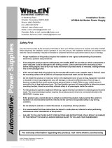
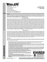
Fig. 1: Station Wiring Diagram

Page 4
2
3
4
6
5
7
1
8a
Digital Voice Board
Siren Control Board
Radio or Landline Board*
Control Board Serial Port
Amplifier LED Status Board
Strobe Control
Paging Interface
Siren Amp 1
Siren Amp 2
Siren Amp 3
Siren Amp 4
Battery Disconnect Switch
Solar Charger Card
(WPS4000-4)
Rotor Relay Module
Battery Charger
(Optional)
b
8
d
c
8
8
9
11
12
10
GUEST
ON
OFF
8
8
8
8
a
b
c
d
9
PTT
ACTIVE
PARTIAL
LED CODES
AC
DC
FULL
ROTOR
FAULT
(RED)
SQUELCH
5
6
7
WPS4000-3 / WPS4000-4
4
12
11 10
3
2
1
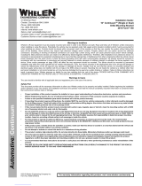
Section I: Overview of System Components
a) Station Component Locations
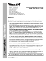
The WPS-4000 High-Power Voice and Siren System is comprised of three basic models:
Model Driver Info Cabinet
WPS-4000-3 Three, 400 Watt Drivers Type II
WPS-4000-4 Four, 400 Watt Drivers Type II
WPS-4000-8 Eight, 400 Watt Drivers Type III
Each system essentially functions in the same manner as do the others. This manual will
provide the necessary information to properly operate, program and diagnose this system
regardless of specific model. If information relevant to a specific model is required, it shall
be presented and noted as such.
The 4000 series systems are comprised of several major components common to all models,
although quantities of some components will vary from model to model.
Fig. 2: WPS 4000-3 / WPS 4000-4 Siren Cabinet Components

Page 5
2
3
4
6
5
7
1
8a
b
c
Digital Voice Board
Siren Control Board
Radio or Landline Board*
Control Board Serial Port
Amplifier LED Status Board
Siren Amp 1
Siren Amp 2
Siren Amp 3
Strobe Control
Paging Interface
Siren Amp 4
Siren Amp 5
Battery Disconnect Switch
Siren Amp 6
Solar Charger Card
Siren Amp 7
Siren Amp 8
Rotor Relay Module
Battery Charger
(Optional)
8
8
f
d
g
e
h
8
8
8
8
8
9
11
12
10
GUEST
ON
OFF
8
8
8
8
8
a
b
c
d
e
8
8
8
9
f
g
h
PTT
ACTIVE
PARTIAL
LED CODES
AC
DC
FULL
ROTOR
FAULT
(RED)
SQUELCH
5
6
7
WPS4000-8
4
12
11 10
3
2
1
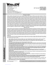
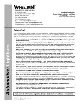
Fig. 3: WPS 4000-8 Siren Cabinet Components

Page 6
b) Station Components Defined
Rotor Control Box - This component (located on the inside of the upper cabinet door)
activates the rotor motor after receiving commands from the control board. It also
transmits the rotor position to the control board. Connections are as follows:
RC1 - Connects the Rotor Control Box to the Control Board
RC2 - Connects the Rotor Control Box to the Rotor
RC3 - Provides Battery Voltage to the Control Box
This component is fused @20Amps.
Control Board - This component (located on the inside of the upper cabinet door) controls
the key functions of the WPS4000 system including:
Tone Generation Remote Activation
Event Timing Rotor Control
Remote Station Status Reporting* (encoding) Local Control
System Diagnostics (incl. SI TEST®)*
* optional equipment
The control board contains a microphone jack for public address and a serial port to allow
connection of a computer (hereafter referred to as a PC) to the remote station. The control
board is also the location of the diagnostic LED’s.
Siren Amps - These components (located on the rear cabinet wall) receive the desired tone
or message generated by the control board, amplify it and deliver it to the siren driver.
Siren Driver - This component (located in the speaker assembly) produces the desired
audible tone or voice message.
Radio or Landline Board (Optional) - This component (located on the inside of the upper
cabinet door) receives signals from either the antenna or landline and delivers them to the
control board for processing. Through the use of the included radio, the station is also
capable of transmitting status information back to the control center.

Page 7
Motherboard - This component (located on the inside of the upper cabinet door) distributes
Battery Voltage and signals to all system components that require this voltage. The
motherboard is fused @5 Amps to protect all connected components EXCEPT for the siren
amplifiers and the rotor (they contain their own fuse). The 2nd motherboard (WPS4000-8
only) distributes signals between the amplifiers and the control board.
AC Battery Charger - This component (located on the bottom front of the cabinet door)
uses 110 VAC (or optional 220 VAC) single-phase service to maintain the stations batteries
at their proper voltages.
Solar Regulator (optional) - This component (located on the bottom front of the cabinet
door) uses electrical energy collected by a pole-mounted solar panel to maintain the station
batteries at their proper voltages.
Ammeter - This component (located on the battery charger panel) provides a visual
indication for the charge current flowing into the batteries from the charger or regulator.
Voltmeter - This component (located on the battery charger panel) provides a visual
indication of the DC voltage across the batteries.
Auxiliary Control Status Board (optional) - This component (located on the right inside
wall of the upper cabinet) is wired to remote switches to facilitate remote operation of a
specific siren station.
Batteries - These components (located on the inside of the lower cabinet) provide the
28VDC necessary for the system to operate.
Battery Disconnect Switch - This component (located on the rear inside wall of the
electronics cabinet) allows all system batteries to be completely disconnected from the
system. NOTE: This switch does not disconnect the batteries from the battery charger or
regulator.
Antenna Poly Phaser (optional) - This component suppresses high-voltage (static) charges
that could be present on the antenna.

Page 8
Antenna (optional) - This component (located on the utility pole) is capable of either
receiving signals broadcast from the control center (one-way) or can both transmit and
receive signals to and from the control center (two-way), depending how the system was
ordered.
Solar Panel (optional) - This component (located on the utility pole) collects solar energy,
converts it to electrical energy and delivers it to the Solar Regulator to maintain the station
batteries at their proper voltage.
Strobe Control Board (optional) - This component (located on the rear inside wall of the
electronics cabinet) is a user-defined device that controls a pole-mounted strobe light. This
light can be configured to activate during specific conditions (example: when any tone or
message is generated).
Intrusion Alarm (optional) - This sensor (located on the controller front panel) detects the
opening of the cabinet door. If the station is equipped with this option, the alarm is
configured to transmit a signal back to the control center.

Page 9
Section II: System Operations
a) Remote Operations
Remote operation of a WPS-4000 series siren involves transmitting signals from the control
center to the desired station. This is accomplished by using either an encoder and
transmitter or, if the station is so equipped, using an auxiliary control status board that has
been wired to switches/controls at the control center. Remote operation is beyond the scope
of this document and will therefore not be addressed. If your system is equipped with an
encoder, please refer to the encoder operating manual for information regarding remote
operation. If your station has been wired to use the auxiliary control status board, refer to
the reference materials provided by the electrical engineer or installer.
b) Local Operations
Local operation is accomplished through the control panel on the front of the station
cabinet. The functions of these controls are as follows:
Cancel Abruptly stops siren tones without the normal “ramp
down” found in several tones. Helpful in the event of an
accidental tone activation.
Wail Produces a slow rise and fall tone.
Attack Produces a faster rise and fall tone (used for designated
Civil Defense National Attack tone).
Alert A steady tone (Civil Defense alert).
Whoop A repetitive rise-only tone.
Hi-Lo An alternating two-tone sound.
Air Horn A pulsing air horn sound.
SI TEST® Initiates SI TEST® tone and the optional diagnostic SI
TEST® routine.
Xmit Carrier Actuates remote station radio transmitter PTT circuit.
When tone squelch is used with the transmitter, the
transmit carrier function is used when adjusting tone
squelch modulation.

Page 10
CANCEL
XMIT
AUDIO
KEYPAD
ARM
WAIL ATTACK ALERT
WHOOP HI-LO AIRHORN
SI-TEST®
DVM
TEST
XMIT
STATUS
XMIT
CARRIER
ROTOR
CW
ROTOR
CCW
Xmit Audio For use with remote station radio transceiver, causes
transmission of DTMF tone via RF link for tone
modulation adjustment.
Xmit Status Transmits station status information and battery voltage
to the control center
DVM Test Activates the Digital Voice Message (DVM) assigned to
the test procedure in the configuration software.
Rotor CW Momentary switch actuates rotor motor to rotate
speaker in a clockwise direction.
Rotor CCW Momentary switch actuates rotor motor to rotate
speaker in a counter-clockwise direction
Keyboard Arm Enables local station operation via keypad. Once
pressed, the keypad remains active until either a)
another keypad button is pressed, or b) 60 seconds have
elapsed, whichever comes first. The Keypad Arm button
must be pressed each time a keypad button is to be
pressed. Note that the Cancel button is always enabled
and does not require Keypad Arm to be pressed.
Fig. 4: Station Control Panel

Page 11
44
33
11
1
QUADRANTS 1-4
RADII
QUADRANT SECTORS
INDIVIDUAL STATIONS
2
3
4
12345
22
44
33
11
22
Section III: Understanding Station Addressing
Every Siren Station in a given area code has its own, unique “Station Address”. This address
allows the user to select an individual or a group of stations. As stated elsewhere in this
manual, a valid station address can be any number from 0000 to 9999. This allows for
10,000 unique addresses; a staggering number of stations to keep track of. Although it is
logistically impossible to have that many stations in a single area code, it does illustrate the
importance of a sensible, intuitive numbering convention for station addresses. This section
will outline two types of conventions
Central Point Source: Quadrant, Sector, Radial & Station
Frequently, warning systems are used to notify the public of emergency situations that may
occur from a single, centralized location. Typically, siren stations would be located
throughout a 360° area surrounding this location for a specified distance from the source. In
this scenario, the Central Point Source convention would be well suited.
For illustration purposes, assume the siren stations are installed within a 5 mile radius of the
Central Point. As such, a Quadrant, Sector, Radial & Station numbering convention would
allow the selection of any of the following:
• any siren station
• all siren stations
• any one of four sectors
• any one of 5 radii within the sectors
The area of coverage in this system, a circle, is divided into 4 quadrants. Each quadrant is
then divided into 4 sectors. Each sector is further divided into 5 segments or radii emanating
from the center of this siren system.

Page 12
In this system, a stations address is structured as follows:
Digit Allocation
1 Quadrant (1 to 4)
2 Sector (1 to 4)
3 Radii (1 to 5)
4 Individual station within a radian
Here are some sample activations to further illustrate this concept.
Sample 1:
A station with address 1354 would be located in:
Quadrant: 1
Sector: 3 of Quadrant 1
Radial: 5
Station: 4
If an operator selects station 1-3-5-4, only that station will be selected, as shown.
1
12
34
5
2345
1354
SINGLE STATION SELECTION
STATION 1354

Page 13
12 34 5
GROUP SELECTION-RADIAL SECTOR
GROUP 134#
Sample 2:
If the activation of a group of remote stations within a whole segment of a radius within a
quadrant and sector is desired, the fourth digit address is substituted with a “Wild Card”,
the “#” pound sign.
An address selection of 1 - 3 - 4 - # would activate the system as follows:
Quadrant: 1
Sector: 3 of Quadrant 1
Radial: 4
Station: # All stations defined by above
This selection is shown below.

Page 14
12 34 5
GROUP SELECTION-SUB-SECTOR
GROUP13##
Sample 3:
Selection of an entire sector can be accomplished by using the following address:
Quadrant: 1
Sector: 3 of Quadrant 1
Radial: # All radial 1 - 3
Station: # All stations defined by above
In selecting a sector, the first two digits of the address are set for the sector address, for
example 1 - 3 (Quadrant 1 - Sector 3). The third and fourth digits are substituted with a #
(Wild Card). Therefore, the address to select all stations in sector 1-3 is 1 - 3 - # - #. This
selection is represented below.

Page 15
12 34 5
GROUP SELECTION-QUADRANT
GROUP###
Sample 4:
The selection of a complete quadrant can be achieved by using the following address:
Quadrant: 1
Sector: # All sectors of Quadrant 1
Radial: # All radials in 1 - 3
Station: # All stations defined by above
When selecting a quadrant, the first digit designates the Quadrant (1). the second, third and
fourth digits are replaced with Wild Cards (#,#,#). Therefore, the address for selecting all
stations in quadrant 1 is 1 - # - # - # as illustrated below.

Page 16
12 34 5
GROUP SELECTION-“ALL-CALL”
GROUP ####
Sample 5:
All stations in a system may be accessed by using the Wild Card (#) for all address numbers.
The address would be # - # - # - #.
Quadrant: # All Quadrants
Sector: # All sectors of all Quadrant
Radial: # All radials
Station: # All stations defined by above
This “All Call” is illustrated as shown.

Page 17
Governmental: County, City & Station
For this next type of address structure, assume that the siren system in question is used
primarily for tornado warnings throughout a major population center. This center
encompasses three counties with each county having no more than ten cities. Two cities
contain more than 50 high-power voice and siren stations.
The following represents a Governmental System 4-digit address configuration, allowing
activation by “All Call”, county group activations, city group activations and individual
station activations:
XXXX
: : : . . . . . . . . . . . : . . . . . . . . . . . Individual Siren Station (0 - 9)
::
: : . . . . . . . . . . . . . . . . . . . . . . . . . . . . . . . . . . . City (0 - 9)*
:
: . . . . . . . . . . . . . . . . . . . . . . . . . . . . . . . . . . . . . . . . . . . . . . . County (0 - 9)
*One digit could also be reserved for unincorporated areas.
An address of 2 - 5 - 4 - 5 would indicate the following individual station:
Siren Station 45, in City 5, in County 2.
The WIld Card (#) permits the use of several different types of group activations. Three
samples follow:
Sample 1: County Activation (1 - # - # - #)
All Siren Stations in all Cities in County 1 will be activated by this transmission.
Sample 2: City Activation (1 - 5 - # - #)
All Siren Stations in City 5 of County 1 will be activated by this transmission.
Sample 3: System All Call (# - # - # - #)
All Siren Stations in all Cities in all Counties will be activated by this transmission.

Page 18
Section IV: Troubleshooting
Audio Loss
If after activating the siren there is no audio output, perform the following procedure step
by step. This procedure will require a digital multimeter.
1. Locate the Audio Presence LED on the controller board (see “Fig. 6: System LED
Diagnostic Indicators” on page 30). When audio is present on the board, this LED
will be on.
2. Activate the WAIL siren tone from the control panel on the siren cabinet. Confirm
that the Audio Presence LED is on. If this LED is not on or if it turns off quickly,
measure the battery voltage. The siren will not activate if battery voltage drops below
19 VDC. Be sure to measure the battery voltage at the same time you activate the
siren. The batteries may show a good float voltage while they are not under load, but
upon activation, the battery voltage may drop below 19 VDC if their capacity is low.
Note that when the siren shuts down and the load is removed from the batteries, the
voltage may rapidly return to 25 VDC or more. If this condition is occurring, the
batteries will need to be replaced. If the voltages are in the normal range, proceed to
step 3.
3. Locate connector J2 on the control board. With your multimeter set to AC volts,
measure across pins 6 and 7 (White with Orange stripe and White with Brown
stripe). With the siren tone running, 5 VAC should be present. If no voltage is present,
the controller board is probably at fault.
NOTE: Confirm that the audio presence LED is on while performing these
measurements. It indicates that the siren controller is still activated. If the specified
voltages are present, proceed to step 4.
4. With the siren tone still active, measure across pin 1 (Blue wire) and pin 2 (Black w/
White trace) on each of the siren amplifiers. 5 VAC should be present at each
amplifier. If so, proceed to step 5. If no voltage is measured, this is indicitive of a
wiring problem between the controller board and the siren amplifiers. Check the
wiring between these components
5. Remove the Red siren driver lead from each siren amplifier. Press “Cancel” on the
control panel and then press “Wail”. Measure across the output of each amplifier
(White Weco connector) with the siren driver disconnected. 70 VAC should be
measured. If this voltage level is measured, proceed to step 6. If this voltage level is
not found and 5 VAC was measured at the input, proceed to step 7.
6. Set your meter to measure resistance at its lowest scale. Measure across each of the
speaker drivers, making sure that at least one wire of each driver is removed from
the power amplifier (or else the transformer in the amp is being measured as well).
Each driver should have a DC resistance of approximately 3 Ohms +/- .3 Ohms. If a
resistance value outside of this range is found, contact factory.

Page 19
7. Set your meter to measure DC Volts. Connect the negative lead of your meter to
ground (one of the solid black wires in the multi-position connector on the amplifier
is a good ground source). With a siren tone activated, measure the following wires for
the following voltages (approximately):
Wire Proper Voltage If not...
Grey 6 VDC Controller Board is suspect
Brown 5 VDC Controller Board is suspect
Solid White (all) 24 VDC Contact Factory
AC Battery Charger
The AC-powered battery charger has two charging modes: Equalization Mode and Float
Charge Mode. The charger is in equalization mode when AC power is first applied; the
charger will stay in equalization mode until the battery voltage reaches approximately
30VDC. Once the battery voltage reaches that point, the charger will switch to float voltage
mode. In that mode it will charge the batteries to the appropriate voltage relative to the
temperature of the batteries (25 to 29VDC).
The AC battery charger contains three circuit boards. The filter board contains a single,
green LED, while two charging boards each contain a pair of LED’s, one green and one
yellow. This pair of LED’s provides diagnostic information for the battery charger. The
following chart defines their various diagnostic states.
Not Working
No AC voltage present
Green LED
Normal Condition
Not Applicable
Yellow LED
OFF
OFF
ON
ON
Charger Operating Properly
AC voltage is present
Equalization voltage mode
Not Applicable
Charging Board
Filter Board

Page 20
Solar Regulator
The following procedure can be performed to confirm proper operation of the solar
regulator:
1. Disconnect the solar panel from the charger. With a DC voltmeter, measure the
voltage across the wires coming from the solar panel. The voltage should be greater
than 32 VDC (NOTE: The solar panel must be in direct sunlight).
2. Reconnect the solar panel to the charger. Monitor the battery voltage with the
cabinet voltmeter. The float voltage will vary between 25 to 30 VDC, depending on
battery temperature. When the solar regulator is charging, the DC LED on the
circuit board will be on. During normal operation the charger will cycle on and off.
The float voltage will vary with battery temperature. The following is a brief description of
the normal charging cycle:
If the float voltage for the current temperature of the batteries is 26 VDC, the regulator will
turn on at 26 VDC (LED will come on) and it will charge the batteries to 28 VDC. Once the
battery voltage reaches 28 VDC, the regulator will turn off (LED will go off), and the
battery voltage will be allowed to drop to 26 VDC. The cycle would then repeat itself. If the
float voltage was 27 VDC, it would cycle from 27 VDC to 29 VDC.
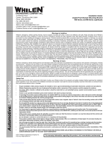
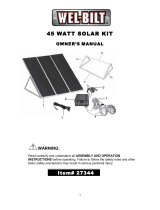
When AC power is applied to the battery charger, the following voltages should be
measured on the wires coming off the charger:
Note: Refer to “Fig. 1: Station Wiring Diagram” page 3.
Pin Position 1
Pin Position 2
Pin Position 3
Pin Position 4
Pin Position 5
Pin Position 6
RED - Battery Voltage to Ground (BLK wire in BC-1)
Note: Voltage present only when siren is
powered up.; this is sourced from the siren
motherboard
Charger output wires (25 to 31 VDC)
GREY - 19VDC from GREY to Ground
(BLK wire in BC-1)
ORANGE - VDC from ORANGE to Ground
(BLK wire in BC-1)
Not Used
WHITE - Charger output wires (25 to 31 VDC)
BLACK -
5
REAR VIEW OF PIN HOUSING
GREY RED
14
25
36
POS. 1 (REF)
ORANGE WHITE
BLACK
Fig. 5:
Solar Regulator
Connector
Pin-outs
/