Page is loading ...

Page 1
Installation Guide:
Inner Edge® Interior Lightbar
with MR8 Take-downs
©2005 Whelen Engineering Company Inc.
Form No.14015E (112008)
®
ENGINEERING COMPANY INC.
51 Winthrop Road
Chester, Connecticut 06412-0684
Phone: (860) 526-9504
Fax: (860) 526-4078
Internet: www.whelen.com
Sales e-mail: autosale@whelen.com
Canadian Sales e-mail: autocan@whelen.com
Customer Service e-mail: custserv@whelen.com
Automotive: Lightbars
Safety First
This document provides all the necessary information to allow your Whelen product to be properly and safely installed.
Before beginning the installation and/or operation of your new product, the installation technician and operator must
read this manual completely. Important information is contained herein that could prevent serious injury or damage.
• Proper installation of this product requires the installer to have a good understanding of automotive electronics,
systems and procedures.
• If mounting this product requires drilling holes, the installer MUST be sure that no vehicle components or other
vital parts could be damaged by the drilling process. Check both sides of the mounting surface before drilling
begins. Also de-burr any holes and remove any metal shards or remnants. Install grommets into all wire
passage holes.
• If this manual states that this product may be mounted with suction cups, magnets, tape or Velcro®, clean the
mounting surface with a 50/50 mix of isopropyl alcohol and water and dry thoroughly.
• Do not install this product or route any wires in the deployment area of your air bag. Equipment mounted or
located in the air bag deployment area will damage or reduce the effectiveness of the air bag, or become a
projectile that could cause serious personal injury or death. Refer to your vehicle owner’s manual for the air bag
deployment area. The User/Installer assumes full responsibility to determine proper mounting location, based
on providing ultimate safety to all passengers inside the vehicle.
• For this product to operate at optimum efficiency, a good electrical connection to chassis ground must be
made. The recommended procedure requires the product ground wire to be connected directly to the NEGATIVE
(-) battery post.
• If this product uses a remote device to activate or control this product, make sure that this control is located in
an area that allows both the vehicle and the control to be operated safely in any driving condition.
• Do not attempt to activate or control this device in a hazardous driving situation.
• This product contains either strobe light(s), halogen light(s), high-intensity LEDs or a combination of these
lights. Do not stare directly into these lights. Momentary blindness and/or eye damage could result.
• Use only soap and water to clean the outer lens. Use of other chemicals could result in premature lens cracking
(crazing) and discoloration. Lenses in this condition have significantly reduced effectiveness and should be
replaced immediately. Inspect and operate this product regularly to confirm its proper operation and mounting
condition. Do not use a pressure washer to clean this product.
• It is recommended that these instructions be stored in a safe place and referred to when performing
maintenance and/or reinstallation of this product.
• FAILURE TO FOLLOW THESE SAFETY PRECAUTIONS AND INSTRUCTIONS COULD RESULT IN DAMAGE TO
THE PRODUCT OR VEHICLE AND/OR SERIOUS INJURY TO YOU AND YOUR PASSENGERS!
For warranty information regarding this product, visit www.whelen.com/warranty

Page 2
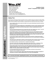
Passenger-Side
Mounting Bracket
Labeled "P"
Position
Inboard
Outboard
-
-
Vehicle
All except
Lo-Pro™
Tahoe
Crown Vic
Impala
Bracket Used
Short Bracket
Short Bracket
Long Bracket
Long Bracket
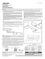
Depending on the vehicle’s roofline, it
may be necessary
to bend the mounting
brackets to position
the housing against
the windshield.
NOTE:
Bracket
Adjust angle
if necessary
Inboard Bracket
Inboard Bracket
Outboard Bracket
Outboard Bracket
Mounting
Fingers
Keyed Opening
Optical Gasket
2005 Impala
Relief for rear
view mirror
stem
Windshield Seal
SEAL
Side View / Seal Installation
Black Oxide Screw
#10-32 X 3/8" Qty 4
Black Oxide Screw
#10-32 X 1/2" / Qty 4
#10 .631 X .060
Flat Washer / Qty. 4
#10 External Tooth
Lock Washer / Qty. 4
Driver-Side
Mounting Bracket
Labeled "D"
06 Crown Vic
onlyLo-Pro™
IMPORTANT! Do not install this product or route any wires in the
deployment area of your air bag (see air bag warning on first page).
IMPORTANT! The lightbar
should be located a minimum
of 16" from any radio antennas!
Important installation note for
Chevrolet Impalas:
When mounting this product in a
Chevrolet Impala, an optical
gasket must be installed as shown
here and below. Failure to do so
could result in reflected light within
the passenger compartment.
Installation:
When routing the wires, it is important to choose a path that
will keep the wires away from excessive heat or any vehicle
equipment that could compromise the integrity of the wires.
1. Locate and install the rubber window seal onto
the lower, leading edge of the housing.
2. Using an appropriately sized Torx head
screwdriver, loosen the three screws
securing the driver-side visor swivel
bracket to the vehicle. Do not remove
these screws.
3. Remove the screws securing the visor clip
to the vehicle. Remove and retain the clip and
all hardware.
4. Locate the driver-side mounting bracket (indicated
with a “D” label) and orient as shown.
5. Slide the mounting bracket fingers between the loosened
swivel bracket and the headliner. The bracket fingers should
straddle the inner section of the swivel bracket when properly oriented.
6. Position the keyed opening of the mounting bracket directly under the
mounting location for the visor clip removed in step 2. With the bracket
in this position, remount the visor clip in its original location using the
original hardware.
7. Firmly tighten any hardware loosened in this procedure.
8. Repeat this procedure for passenger-side (indicated with a “P” label).
Wiring:
IMPORTANT: All customer supplied wires that connect to the
positive terminal of the battery must be sized to supply at least
125% of the maximum operating current and FUSED at the battery to
carry that load. DO NOT USE CIRCUIT BREAKERS WITH THIS
PRODUCT!
Operation:
With the lightbar on:
• Applying +12 volts to the WHT/BLK wire activates the take-downs.
• With the take-downs activated, applying +12 volts to the BLUE wire will
cause the take-down lights to flash.
• Applying +12 volts to the ORANGE wire causes all lightheads to flash.
• Apply +12 volts to the WHT/ORG wire to activate the steady burn
lightheads (optional).
Scan-Lock™ / WHITE/GREEN
To change a flash pattern, turn on the desired lighthead:
CYCLE THROUGH ALL PATTERNS: To cycle forward, apply +12 volts
to the WHT/GRN wire for less than 1 second and release. To cycle
backward, apply +12 volts to the WHT/GRN wire for more than 1 second
and release.
SET A PATTERN AS DEFAULT: When the desired pattern is displayed allow it
to run for more than 5 seconds and this pattern will become the default pattern.
RESET TO THE FACTORY DEFAULT PATTERN: Turn off power and apply
+12 volts to the WHT/GRN wire while turning power on.
A Normally Open Momentary Switch can be used to control Scan-Lock.
Available Scan-Lock™ Flash Patterns: Signal Alert™ 75 Alternating > Signal
Alert™ 75 In-Out > SignalAlert™ 75 Left to Right > SingleFlash 90 Alternating >
SingleFlash 90 In-Out SingleFlash 90 Left to Right > CometFlash® 75 Alternating >
CometFlash® 75, In-Out > CometFlash® 75, Left to Right > SingleFlash 75
Alternating SingleFlash 75 In-Out > SingleFlash 75 Left to Right > SingleFlash 150
Alternating > SingleFlash 150 In-Out > SingleFlash 150 Left to Right DoubleFlash 75
Alternating > DoubleFlash 75 In-Out > DoubleFlash 75 Left to Right > ActionFlash™
Alternating > ActionFlash™ In-Out > ActionFlash™ Left to Right > RandomFlash >
ActionScan™ Alternating > ActionScan™ In-Out > ActionScan™ Left to Right.
Hi/Low Power / BROWN
This feature allows the user to step the unit down to low power operation
for nighttime use. The type of switch used depends on how the operator
wishes the Hi/Low feature to function:
Latching Mode: By applying positive voltage to the BROWN wire for less than
1 second, the lightbar is “latched” into low power. The unit must be turned off
and then back on to restore normal, high power operation (A momentary
switch is preferred).
Level Mode: Applying positive voltage to the BROWN wire for more than 1
second holds the lightbar in low power mode until voltage is removed (A toggle
switch is preferred).
9. Using the hardware provided (#10-32 x 3/8” black oxide screws),
secure the lightbar to the mounting brackets. Tighten this
hardware firmly. Route lightbar cable down vehicle A-pillar to your
control head. Make wiring connections as shown here.
BRN
WHT/GRN
WHT/ORG
BLUE
WHT/BLK
ORG
RED
BLK
Flasher +12V
"Low Power"
"Scan-Lock™"
Steady Burn lightheads / Optional
Causes Takedowns to flash.
ActivatesTakedowns.
Causes all lightheads to flash.
Customer supplied switches
Fuse @ 10 AMPS
BATTERY
Wire Color Function
Fuse @ 5 AMPS
Flasher / Ground (-)

Page 3
117
24
18 19 20 21 22 23
25
244
43
3
4
5
6
34
31 42
32
30
7
14
15
2
26
28
27
16
8
11
9
12
10
13
29
24
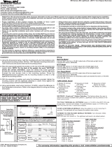
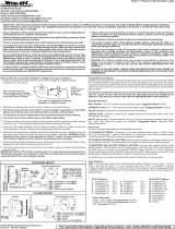
LABEL
SCREW #4-40 X 3/8 LG PPHMS/
LAMP MR8 20 WATT/
PAD INSULATOR MR8 LIGHT//
TY WRAP 6" BLACK
HARNESS ASSY / INNER EDGE LINEAR
HOUSING INT LIGHTBAR '06 IMPALA//
LIGHT PIPE
SPACER MTG - PCB/
SCREW, M4.2 X 12MM, BLACK OXIDE
HOUSING INT LIGHTBAR '05 EXPEDITION//
HOUSING SOCKET - 8 POS AMP CMNL/
LAMP BASE ASSY MR8 - 2 POS AMP/
34-21120D0-20
2
14-040216-060
15-M23B1C-120
26-0215001-06
11-484349-000
11-484345-000
A/R
A/R
1
15
4
10-0523205-__
38-0623178-00
46-0764408-00
39-0408323-04
46-0743274-01
68-1900250-30
20-0017569-00
2
2
4
1
TY WRAP 3"
MOUNTING KIT '04/05 CROWN VIC/
MOUNTING KIT SUBURBAN/TAHOE/
MOUNTING KIT IMPALA '05/
MOUNTING KIT '05 06 CROWN VIC/-
MOUNTING KIT '05 EXPEDITION/
MOUNTING KIT IMPALA '06/
SUPER BONDER #495 LOCKTITE
SEAL / EXTRUDED HOUSING WINDSHIELD//
66-0715289-00
26-0215001-03
01-0484269-00
01-0484269-02
01-0484269-01
01-0484269-03
01-0484269-04
N/A
38-0543284-22
22
23
31
32
33
34
35
1
2
1
A/R
A/R 36
37
38
39
40
A/R
A/R
A/R
A/R
24
25
26
27
28
29
30
41
42
43
A/R
A/R
2
HOUSING INT LIGHTBAR '05 IMPALA//
BRACKET LIGHTHEAD/
COVER / MR8
GROMMET
SCREW GROMMET #6 #8 FASTEX
PLATE MOUNTING/
LENS CLEAR NON-OPTIC SNAP-ON//
PCB ASSY CONT. BD SMT 500 LINEAR//
LTHEAD ASSY LINEAR AMB-STDY//-LED®
LTHEAD ASSY LINEAR BLU-STDY//-LED®
LTHEAD ASSY LINEAR WHT-STDY//-LED®
LTHEAD ASSY LINEAR LED RED-STDY/-®/
HOUSING INT LIGHTBAR '04 '05 CROWN VIC//-
HOUSING INT LIGHTBAR SUBURBAN/TAHOE//
HOUSING NT LIGHTBAR '05 '06 CROWN VIC//-
LTHEAD ASSY LINEAR GRN-STDY//-LED®
LTHEAD ASSY SPLIT LINEAR RED BLUE// /-
BRACKET MOUNTING/
CABLE ASSY 9 C 18GA. TPR 20'/-
SCREW #8-32 X .312 PPHMS SS BLK OX/
INNER EDGE®INTERIOR SERIES LIGHTBAR
SCREW #6 X 3/8 PPH PLASTI-LOK SS BLK OX/
14-082215-050
01-0684343-( )
07-243216-023
46-0743243-01
15-06521B-060
01-0264260-12
07-284337-023
13-062C40-16J
07-784340-023
01-0264260-22
01-0264260-32
01-0264260-52
01-0264260-42
02-0164204-00
11-264117-006
11-484270-000
21-11121602-0
11-484335-000
68-3963604-30
01-0264260-J2
11-484304-000
11-484320-000
A/R
2
3
4
10
ITEM PART NUMBER DESCRIPTION
QTY
11
12
13
14
15
A/R
A/R
7
1
216
17
18
19
20
A/R
A/R
1
A/R
4
5
6
7
8
9
10
1
25
1
A/R
A/R
A/R
12
11
21
A/R
#8 INTERNAL TOOTH LOCK WASHER SS
16-0821220-400
44
8

Page 4
POS. 8 = BLACK
POS. 7 = BROWN
POS. 3 = WHT/BLK
POS. 2 = ORANGE
WIRE CONNECTIONS
POS. 5 = WHT/ORG
POS. 6 = WHT/GRN
POS. 1 = RED
POS. 4 = BLUE
P7
15
29
2
1
28
18
31 36
3
9
21
12 10
4
11
19
20 22
30
16
6
14
5
7
8
13
17
1
8
32
23 24 25
26 27
11
2
1
4
1
4
1
1
1
2
1
29
11
2
11
29
2
20
2
4
24
2
4
1
1
10
1
1
12
1
18
4
18
1
4
HOUSING FRONT FULL 2006 CROWN VICTORIA/
FULL LO-PRO 10-LT 2 T-D™INNER-EDGE®
FULL LO-PRO™INNER-EDGE®12-LT 2 T-D
BRACKET LIGHTHEAD MOUNT
PLATE MOUNTING/
SCREW 8-32 X 5/16 PPHMS SS BLACK/
SCREW 4 X 3/4 PPHMS SS/
SCREW 6 X 3/8 PPH PLASTI-LOK/
SCREW GROMMET #6/8/
ASS'Y LAMP BASE MR8 2 POS AMP
SCREW 4 -40 X 1/2 PPHMS SS BLACK/
LAMP MR8/
3/8 GROMMET
COVER MR8/
BRACKET MOUNTING/
SCREW, M4.2 X 12MM, BLACK OXIDE
ASS'Y PCB CONNECTOR/
HEADER .1" X 2 POS DOUBLE/
ASSY PCB MOTHER/CONTROL BOARD/
LIGHT PIPE
01-0684643-01
13-062C40-16J
07-284506-023
07-784507-023
07-243360-023
15-M23B1C-120
14-082215-050
02-0164765-00
40-0620400-03
14-040216-120
68-1900375-30
11-264117-006
02-0185989-00
15-06521B-060
46-0743274-01
34-21120D0-20
14-040216-080
21-11091202-0
11-484501-000
01-0684643-00
2
3
ITEM PART NUMBER DESCRIPTION
QTY QTY
11
12
13
14
15
16
17
18
4
5
6
7
8
9
10
1
FULL LO-PRO 10-LT 2 T-D™INNER-EDGE®
FULL LO-PRO 12-LT 2 T-D™INNER-EDGE®
01-0684643-01
01-0684643-00
ITEM PART NUMBER DESCRIPTION
QTY QTY
A/R A/R ASS'Y PCB 3 LED ARRAY - BLUE/
22
6
4
6
6
A/R
10 12
A/R
1 LIGHT CONNECTOR BOARD SMT/
ASS'Y PCB 3 LED ARRAY - AMBER/
CO-THERM INSULATOR
LINEAR ASSY
REFLECTOR TIR/
02-0164748-20
02-0146537-00
02-0164748-10
02-0323306-00
56-023279-000
68-5964727-00
46-0764933-00
38-0623178-00
39-1M17672-08
46-0743401-01
01-0484643-00
26-0215001-06
10-0523205-__
02-0164748-50
02-0164748-40
02-0164748-30
38-0543284-45
46-0743403-00
A/R A/R
A/R
A/R A/R
A/R
1
1
1
1
1
1
1
1
1
1
1
1
1
1
1
1
22
HARNESS INTERCONNECT/
HOUSING PLUG 8 POS/
HARNESS TAKE-DOWN/
KIT MOUNTING 12 LT 2006 CROWN VICTORIA/
ASS'Y PCB 3 LED ARRAY - RED/
ASS'Y PCB 3 LED ARRAY - GREEN/
ASS'Y PCB 3 LED ARRAY - WHITE/
ASSY CABLE INPUT 18 GA 20'/
TY WRAP 6"/
LABEL
SEAL EXTRUDED/
PAD / INSULATOR-MR8 LIGHT
19
20
22
23
31
32
33
34
35
36
24
25
26
27
28
29
30
21
/