Page is loading ...

Page 1
Installation Guide:
CenCom Core-S™ Main Control Box
Model: C399S / C399SH
C399S6
C399S7
C399S6H
C399S7H
©2023 Whelen Engineering Company Inc.
Form No.14F14C (071323)
Automotive: Sirens/Switches
For warranty information regarding this product, visit www.whelen.com/warranty
DANGER! Sirens produce extremely loud emergency warning tones! Exposure to these tones without proper and adequate hearing protection, could
cause ear damage and/or hearing loss! The Occupational Safety & Health Administration (www.osha.gov) provides information necessary to determine
safe exposure times in Occupational Noise Exposure Section 1910.95. Until you have determined the safe exposure times for your specific application,
operators and anyone else in the immediate vicinity should be required to wear an approved hearing protection device. Failure to follow this
recommendation could cause hearing loss!
• Proper installation of this product requires the installer to have a good understanding of automotive electronics, systems and procedures.
• Whelen Engineering requires the use of waterproof butt splices and/or connectors if that connector could be exposed to moisture.
• Any holes, either created or utilized by this product, should be made both air- and watertight using a sealant recommended by your vehicle
manufacturer.
• Failure to use specified installation parts and/or hardware will void the product warranty.
• If mounting this product requires drilling holes, the installer MUST be sure that no vehicle components or other vital parts could be damaged
by the drilling process. Check both sides of the mounting surface before drilling begins. Also de-burr the holes and remove any metal shards
or remnants. Install grommets into all wire passage holes.
• If this manual states that this product may be mounted with suction cups, magnets, tape or Velcro®, clean the mounting surface with a 50/50
mix of isopropyl alcohol and water and dry thoroughly.
• Do not install this product or route any wires in the deployment area of your air bag. Equipment mounted or located in the air bag deployment
area will damage or reduce the effectiveness of the air bag, or become a projectile that could cause serious personal injury or death. Refer to
your vehicle owner’s manual for the air bag deployment area. The User/Installer assumes full responsibility to determine proper mounting
location, based on providing ultimate safety to all passengers inside the vehicle.
• For this product to operate at optimum efficiency, a good electrical connection to chassis ground must be made. The recommended
procedure requires the product ground wire to be connected directly to the NEGATIVE (-)
battery post (this does not include products that use cigar power cords).
• If this product uses a remote device for activation or control, make sure that this device is
located in an area that allows both the vehicle and the device to be operated safely in any
driving condition.
• It is recommended that these instructions be stored in a safe place and referred to when
performing maintenance and/or reinstallation of this product.
• FAILURE TO FOLLOW THESE SAFETY PRECAUTIONS AND INSTRUCTIONS COULD RESULT
IN DAMAGE TO THE PRODUCT OR VEHICLE AND/OR SERIOUS INJURY TO YOU AND YOUR
PASSENGERS!
CAUTION
Loud siren noise can cause
hearing damage and/or loss.
Refer to OSHA Section 1910.95 prior
to putting ANY siren into service!
Wear
Protection!
ACTIVATION OF THIS
SIREN MAY DAMAGE
UNPROTECTED EARS!
Warnings to Installers
Whelen’s emergency vehicle warning devices must be properly mounted and wired in order to be effective and safe. Read and follow all of Whelen’s written
instructions when installing or using this device. Emergency vehicles are often operated under high speed stressful conditions which must be accounted for
when installing all emergency warning devices. Controls should be placed within convenient reach of the operator so that they can operate the system without
taking their eyes off the roadway. Emergency warning devices can require high electrical voltages and/or currents. Properly protect and use caution around
live electrical connections.Grounding or shorting of electrical connections can cause high current arcing, which can cause personal injury and/or vehicle
damage, including fire. Many electronic devices used in emergency vehicles can create or be affected by electromagnetic interference. Therefore, after
installation of any electronic device it is necessary to test all electronic equipment simultaneously to insure that they operate free of interference from other
components within the vehicle. Never power emergency warning equipment from the same circuit or share the same grounding circuit with radio
communication equipment. All devices should be mounted in accordance with the manufacturer’s instructions and securely fastened to vehicle elements of
sufficient strength to withstand the forces applied to the device. Driver and/or passenger air bags (SRS) will affect the way equipment should be mounted. This
device should be mounted by permanent installation and within the zones specified by the vehicle manufacturer, if any. Any device mounted in the deployment
area of an air bag will damage or reduce the effectiveness of the air bag and may damage or dislodge the device. Installer must be sure that this device, its
mounting hardware and electrical supply wiring does not interfere with the air bag or the SRS wiring or sensors. Mounting the unit inside the vehicle by a
method other than permanent installation is not recommended as unit may become dislodged during swerving; sudden braking or collision. Failure to follow
instructions can result in personal injury. Whelen assumes no liability for any loss resulting from the use of this warning device. PROPER INSTALLATION
COMBINED WITH OPERATOR TRAINING IN THE PROPER USE OF EMERGENCY WARNING DEVICES IS ESSENTIAL TO INSURE THE SAFETY OF
EMERGENCY PERSONNEL AND THE PUBLIC.
Warnings to Users
Whelen’s emergency vehicle warning devices are intended to alert other operators and pedestrians to the presence and operation of emergency vehicles and
personnel. However, the use of this or any other Whelen emergency warning device does not guarantee that you will have the right-of-way or that other
drivers and pedestrians will properly heed an emergency warning signal. Never assume you have the right-of-way. It is your responsibility to proceed safely
before entering an intersection, driving against traffic, responding at a high rate of speed, or walking on or around traffic lanes. Emergency vehicle warning
devices should be tested on a daily basis to ensure that they operate properly. When in actual use, the operator must ensure that both visual and audible
warnings are not blocked by vehicle components (i.e.: open trunks or compartment doors), people, vehicles, or other obstructions. It is the user’s responsibility
to understand and obey all laws regarding emergency warning devices. The user should be familiar with all applicable laws and regulations prior to the use of
any emergency vehicle warning device. Whelen’s audible warning devices are designed to project sound in a forward direction away from the vehicle
occupants. However, because sustained periodic exposure to loud sounds can cause hearing loss, all audible warning devices should be installed and
operated in accordance with the standards established by the National Fire Protection Association.
Safety First
This document provides all the necessary information to allow your Whelen product to be properly and safely installed. Before beginning the installation and/or
operation of your new product, the installation technician and operator must read this manual completely. Important information is contained herein that could
prevent serious injury or damage.
WARNING: This product can expose you to chemicals including Lead which is known to the State of California to cause cancer and birth defects or
other reproductive harm. For more information go to www.P65Warnings.ca.gov.
51 Winthrop Road
Chester, Connecticut 06412-0684
Phone: (860) 526-9504
Internet: www.whelen.com
Sales e-mail: [email protected]
Customer Service e-mail: [email protected]
®
ENGINEERING COMPANY INC.

Page 2
Specifications:
Input Voltage . . . . . . . . . . . . . . 12.8 VDC ±20% - Negative Ground Only
Main Input Current . . . . . . . . . . . . . . . . . . . . . . . . . . . . . . 70 Amps Max.
Siren Input Fuse . . . . . . . . . . . . . . . . . . . . . . . . . . . . . . . . . . . . 15 Amps
Stand-by Current (no ignition) . . . . . . . . . . . . . . . . . . . . . . . . . . . . 1 mA
Operating Temperature. . . . . . . . . . . . . . . . . . . . . . . . . . -30°C to +60°C
Storage Temperature . . . . . . . . . . . . . . . . . . . . . . . . . . . -40°C to +70°C
Humidity. . . . . . . . . . . . . . . . . . . . . . . . . . . . . . . . 99% (Non-condensing)
Siren Amplifier Module Module
Standard Audio Bandwidth @25 Watts . . . . . . . . 300 to 10000 Hz ±3db
Distortion @25Watts . . . . . . . . . . . . . . . . . . . . . . . . . . . . . . 1% Maximum
Output Voltage @15VDC @11 ohms . . . . . . . . . . . . ...24Vrms Maximum
Speaker Impedance. . . . . . . . . . . . . . . . . . . . . . . . . . . 11 Ohms Minimum
Howler Audio Bandwidth @25 Watts. . . . . . . . . . . . . . . . 200-10000 Hz
High Current Outputs
4 High Current Outputs: . 2 - 15 Amps Max. 2 - 10 Amps Max. (internally
limited)
NOTE: Total current of High Current Outlets not to exceed 60 Amps
1 Dry Contact Relay: 15 Amp (Fused)
Low Current Outputs
12 Low Current Outputs . . . . . . . . . . . . . 2 Amps Max (internally limited)
6 Digital Inputs / 4 Analog Inputs / 1 Ignition Sense
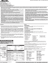
Installation:
This siren is designed to be mounted directly onto the dash or other sur-
face through the use of a bail strap mounting bracket. The unit may also
be mounted into your vehicle’s console (if so equipped).
Bail Mount:
1. Locate a suitable mounting location.
2. Position bail strap in selected mounting location and drill mounting
holes, then secure the bail strap to the vehicle.
3. Secure the siren to the bail strap using the included hardware.
Console Mount:
1. Console manufacturers offer mounting kits that include all the
necessary hardware and brackets to mount this unit into their console.
The console mount brackets are secured onto the unit in the same way.
Please refer to the manual included with your console.
Remote Mounting Solution:
1. Install the two remote mounting brackets using the included hardware.
2. Position and install the Core-S™ / Remote Mounting bracket assembly
and secure it with the included four mounting screws.
Dimensions:
Bail Mount:
Remote Mounting Solution:
2.50

Page 3
Wiring:
All customer supplied wires that connect to the positive terminal of
the battery must be sized to supply at least 125% of the maximum
operating current and FUSED at the battery to carry that load. DO
NOT USE CIRCUIT BREAKERS WITH THIS PRODUCT!
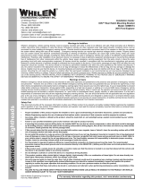
Main Power (J16):
1. Locate the connector with RED & BLK wires, sized to fit into the system
power connectors (included).
2. Route the two RED 10 AWG wires (included) from the Core-S™ module
to an unused circuit fused @ 40 Amps each wire (the fuse panel, for
example). Do not connect to this circuit yet.
3. Route the BLACK 10 AWG wire (included) from the Core-S™ module to
the vehicle’s chassis ground typically adjacent to the battery.
4. Complete the connections and plug the connectors into the Core-S™
Module.
Programmable Inputs:
There are 6 digital and 4 Analog programmable inputs in the Core-S™
system.
Digital Inputs (J9) (Pins 1-6)
These digital inputs can be configured to detect either a positive or ground
activated signal.
Analog Inputs and Ignition Sense(J9)
Analog Inputs (Pins 7,8,9,10)
These inputs can detect a varying, analog voltage range. The output
signal line from devices such as a K-9 temperature sensor may be
connected to these inputs.
Ignition Sense (Pin 12)
This input should be wired to an ignition signal and controls when the
Core-S™ system turns on (when ignition is detected) and when the
system turns off (when ignition line turns off). The Core-S™ system
turning off can be further configured by programing a Shutdown Delay to
keep the system active after the ignition signal turns off.
Switched Outputs:
Low Current Outputs (J15)
• 2 Amp Active High, internally limited (Pins 1-11)
• 2 Amp Active Low, internally limited (Pin 12)
High Current Outputs (J14)
These outputs can be programmed by the Whelen Command® software
to activate in any combination, they also can be set up to source current at
VBAT.
• 15 Amp Max, internally limited (Pins 1-2,)
• 10 Amp Max, internally limited (Pins 3-4)
Dry Contact Relay (J3) (See “Hands Free Siren”)
• 15 Amp Max, Fused
• Pin 1 is the Normally Open terminal.
• Pin 2 is the relay’s Common terminal.
• Pin 3 is the Normally Closed terminal.
Siren Speaker (J1)
Note: Use the GREY (+) and ORANGE (-) wires when installing a
Howler® speaker.
1. Route the ORANGE, GREY, YELLOW and BROWN 18 AWG wire
(included) from the amp/relay module to the siren speakers.
2. Connect the YELLOW (+) and BROWN (-) wires to speaker one.
3. Connect the GREY (+) and ORANGE (-) wires to speaker two.
Audio signals (J10):
Radio Rebroadcast (Pins 1, 2)
Two blue wires are used to connect the audio output of your two-way radio
to the Whelen Siren Module for radio rebroadcast. (Optional connection).
NOTE: Radio rebroadcast will NOT work with radios requiring
amplified remote speakers! If your remote speaker is amplified (i.e.
contains a power amp circuit in the speaker assembly), the signal
from the radio will not be appropriate for this input.
Locate the two wires that connect the external speaker to the two-way
radio. Splice one of the blue wires into one of the radio’s speaker wires,
then splice the other blue wire into the other radio speaker wire.
Radio Repeat Volume Adjustment
Locate the Radio Repeat adjustment potentiometer on the left side of the
Core module. Set the volume of the vehicle’s two-way radio to its normal
operating level. Press the RAD button on the control head to activate
Radio Repeat. As incoming transmissions are received, adjust the Radio
Repeat potentiometer to set the desired level. Turn the potentiometer
clockwise to increase and counter-clockwise to decrease the level.
Auxiliary Audio Input (Pins 4,5)
Two green wires are proved to connect the auxiliary audio output of an
appropriate Whelen device to this unit.
Cabin Speaker (Pins 3,6)
The yellow wire goes to the positive (+) speaker terminal, and the white-
yellow wire goes to the negative (-) speaker terminal.
Note: Recommended cabin speaker is 5 Watts at 8 Ohm.
Microphone (J11):
Attach the microphone extension cable to this connector, route the cable
to the desired location in the vehicle and secure the other end to a fixed
location and then attach the microphone.
PA Volume Adjustment
To adjust the PA volume refer to the WeCan® Whelen Command®
software.
USB-C Programming Port (J7):
Attach to computer using USB-C cable when programming the system
with the Whelen Command® Software. NOTE: Charging-only Cables
from multiple mobile devices (i.e. cell phones or tablets) are not
recommended for data transfer use. Not all cables are capable of
charging and data transfer.
Ethernet Port (J2):
To be used with a Whelen Ethernet device.
CAN Communications (J8,J4):
J8 is the control link between all WeCanX® devices. Core-S™ ties into the
vehicles OBDII port using J4.

Page 4
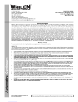
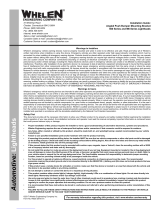
Hands-Free Siren / Optional:
You may either use a customer supplied relay capable of handling the cur-
rent of your vehicle horn connected as shown or the Dry Contact Relay
located on the main control box (recommended)
Connecting the USB:
Connect a computer with Whelen Command® software via USB once the
boot-up and initialization process is complete to transfer a new
configuration. If you send a configuration to Core-S™ with only USB
connected, the configuration will not be sent to all devices until power and
ignition are applied to Core-S™ with WeCanX® connection maintained to
powered devices. Note: Make sure power is applied to Core-S™ before
connecting USB.
If you are updating the firmware of the main Core-S™ or transferring/
extracting a new configuration, connect to Core-S™ via a USB-C
connector without external power. This provides communication and
power to the central controller only. If there is no configuration currently on
Core-S™, the status indicator will be steady Orange. If there is a valid
configuration, the status indicator will be steady Green. If there are no
OBDII or analog connections, the status indicator will be steady Blue.
Booting up Core-S™:
When you first apply power and ignition to Core-S™, the status indicator
will blink Magenta to indicate that it is booting up. After 2 seconds,
Core-S™ should complete boot up and go through the initialization
process outlined in the next section.
Troubleshooting Boot up:
If the Status indicator is steady Red (not flashing) and the Activity indicator
is off, then there is a firmware corruption. After power and ignition is
applied to the unit, connect USB to the unit and open Whelen Command®
software. Follow the update firmware instructions below to see if this fixes
the corruption. If this does not work, then the device must be sent in for
repair.
Initializing Devices and Updating Firmware:
Initialization:
To ensure proper initialization, make sure all devices are connected via a
WeCanX® connector and are powered with 12VDC BEFORE applying
ignition to Core-S™. When ignition is applied, Core-S™ will then register
all devices it can communicate with through the WeCanX® bus. The
Status indicator will flash WHITE, and the Activity indicator will flash Blue,
showing message communication.
NOTE: If you have no configuration on Core-S™, the Status indicator
will be steady Orange. If a configuration is present, the Status
indicator will be a steady Green. When the status indicator is no longer
flashing White, the initialization process is complete. USB can now be
plugged into Core and hooked up to Whelen Command®.
Updating Firmware:
To update the firmware in Whelen Command®, ensure you have gone
through the Core-S™ initialization process and that all devices are
connected via WeCanX® and powered with 12VDC. Plug in USB, open
Whelen Command®, and select “Core-S™” from the product menu. Click
the “W” icon in the top left corner and select “Update Firmware” from the
list. Click the refresh button to see a list of all available devices connected
to Core-S™. Verify that every device you have connected is displayed. If
any are missing, restart the initialization process and try again. Update the
firmware of any device that needs it. Do not remove the WeCanX®
connection or power until Whelen Command® states the process has
been completed. The firmware update is completed one device at a time.
That device's diagnostic indicator will slowly flash Blue to indicate that the
firmware is loading. The device's diagnostic indicator will start blinking
faster to indicate that the firmware is currently installing. Note: When the
peripheral devices have finished updating, the diagnostic indicator
on each respective device will turn off unless the diagnostic
indicators are configured to be on, in which case they will turn Green
when finished.
Troubleshooting Firmware Updates:
If Whelen Command® informs you that the transfer failed, unplug the USB
and cycle power to all units. Then plug the USB back into Core-S™ and hit
the refresh button on the Whelen Command® “Update Firmware” page.
Repeat the firmware update process if the firmware is not up to date. If a
device fails to update and all connections are intact, its diagnostic
indicator will remain blinking blue to indicate that it is loading the firmware.
After reinitializing the system, the device will show up on the “Update
Firmware” page with firmware version “Unknown”. From there, you can
then update the firmware to the newest version. Note: If at any point
your device stops working and you have verified that all the proper
connections are intact, re-initialize and check for firmware updates.
Configuring Devices:
The fastest and easiest way to configure your system is immediately after
the initialization and firmware update processes are complete. An up-to-
date system allows for easily importing connected devices into a new
configuration using the “Detect via USB” feature on the “My Hardware”
page. All devices presently communicating with Core-S™ will populate the
hardware list. Certain devices will not automatically populate due to the
need for further configuration, such as lightbars, Inner edges, and Traffic
Advisors. Whelen Command® will alert the user to these devices, but they
will not automatically populate the list. Core-S™ will show a steady Cyan
status indicator if a device is connected to the control system but is not in
the configuration. Note: Any device that you have multiples of require
configured installation ID’s.
Bosch™ Style
(Tyco-P&B P/N:VF4-45F11)
(customer supplied)
Dry Contact Relay
Switched as output 23
(recommended)
To Vehicle Car Horn
From Vehicle
Horn Relay
To Any Output
To any Input configured
as Horn Ring
30
87A
85 86
87
Generic Style Relay
(customer supplied)
To Any Output
To any Input
configured as
Horn Ring
To Vehicle
Car Horn
NO
NC
From Vehicle Horn Relay
J3
DRY CONTACT
RELAY
HORN RING
Cut connection
between horn ring
and factory horn
3 - ORG
2 - RED
1 - BRN
Normally Closed - To
Vehicle Car Horn
COMMON - From
Vehicle Horn Relay
Normally Open
Horn Ring Input
If the horn
connection is
positive 12V, the
load should not
exceed 15 AMPS.
To Transfer Horn for HF, activate
J3 - 1, 2, 3 dry contact configuration
VEHICLE
HORN
To Input 1
WHT/BRN

Page 5
Transferring Configuration Files to Device:
There are two ways to transfer configurations to your system. You can
connect to Core-S™ via USB or over the air using WHELEN CLOUD
PLATFORM®. Core-S™ must be connected to power and ignition during
a transfer via USB, or the configuration will not transfer to the internal
siren or IO. For this configuration to reach other WeCanX® devices,
Core-S™ must be connected and initialized to the other devices in the
configuration. Core-S™ diagnostic indicators are always on. During the
transfer, the Status indicator will be solid or flashing white. In contrast, the
activity indicator will flash Blue to show communication. A finished
configuration is indicated by the device's diagnostic indicator turning solid
Green or turning off. (This depends on whether or not you have turned
device diagnostic indicators on in “configuration settings”). If a large DVM
tone is being transferred to an external siren or howler, the device will
display a blinking Red indicator while receiving the configuration data only
if the diagnostic indicator is enabled. If the indicators are turned off, you
will only have the Status and Activity indicators on the Core-S™ controller
to determine the state of the configuration.
Idle States:
After a configuration transfer, Core-S™ will enter an idle state and wait for
inputs/instructions pending the trigger of a programmed event. Core-S’s™
activity indicator is always on and will blip every time it is processing a
communication. If an analog or OBDII connection is present, the activity
indicator will always show activity in an idle state. The activity indicator will
blip every time any input state change is sensed. You can watch for the
Activity blip on Core-S™ when testing an input to verify the input state
change. If no blip occurs, verify you have made all the right connections. If
everything on the WeCanX® bus is initialized and there is a valid and fully
populated configuration, then the Core-S™ status indicator will be a
steady Green. If there are devices on the bus that are initialized but not
present in the configuration, then the status indicator will be steady Cyan.
If there is no valid configuration on Core-S™, then the status indicator will
be steady Orange.
System Shutdown:
The Core-S™ system is designed to have constant 12VDC power. Every
device, including the main Core-S™ controller, has a built-in sleep
function to minimize battery drain. Applying ignition voltage to Core-S’s™
ignition pin will wake the system, and removing the ignition voltage will put
Core-S™ to sleep. After 3 seconds, all other devices connected to
Core-S™ via WeCanX® will go to sleep and turn off diagnostic indicators.
Installation IDs
While detecting via USB, Whelen Command® will prompt an “Installation
IDs are not set” error if more than one of the same device types is
recognized. As a rule, if you have more than one of the same device
types, you must manually set the installation ID. For Example, two
Remote 16s would need their IDs set, but one Remote 16 and one
Remote 8 would not. Two Arges® Remote Spotlights would need their IDs
set, but one Arges® Remote Spotlight and one Arges® Profocus would
not. Click on the “W” icon on the top left of the “My Hardware” page and
select “Assign Installation IDs”. All devices you are setting will have a
default ID of unassigned. Unplug all the devices you plan to rename
except for one. Refresh the list and select the number you want from the
drop-down menu, check the box next to the device and click assign. After
you have assigned the device, you can add each subsequent device one
at a time and iterate the installation ID. If you have set installation IDs
before you “Detect via USB”, Whelen Command® will automatically
populate the hardware list with the correct configuration ID to match the
Installation ID. Note: The installation ID numbers only differentiate
between devices of the same device type, meaning that you can have
multiple devices with the same installation ID if they are different
devices types.
Troubleshooting Installation IDs:
Installation IDs may not have been set if you have more than one of the
same device types in your configuration and only one of them is working.
After firmware initialization, check to ensure that you have proper
connections and that all identical device types have installation IDs set.

Page 6
Core-S™ Diagnostic Indicator Troubleshooting
System
Status
Status
Indicator
Colors
Troubleshooting Steps
Booting Magenta A CoreOS device firmware update can take up to 30 seconds to install. If the diagnostic LED is still magenta after
30 seconds, contact customer service.
Orange
Unconfigured
Node Cyan
Communication
Blue Flash A blue flashing LED indicates Core-S™ detects an input change. Large siren DVMs can take up to 15 minutes to download.
If power is lost during transfer, the process will restart on power-up. The siren will not function until this process is complete.
Missing
Configuration Transfer a valid configuration from Whelen Command®.
Verify that all peripheral devices connected to Core-S™ are included in your Whelen Command® configuration.
Status Indicator LEDs
The is a blue LED thatActivity Indicator flashes to indicate when the device is processing data.
The is a multi-color RGB LED that indicates the system status and error conditions.Status Indicator
State Table - Update Status
System Status Status Indicator
Colors Details
Booting Magenta The system is booting up. When a CoreOS device firmware update is being installed, this process could
take up to 30 seconds.
System Failed to Boot Red A fatal error occurred and the system was unable to boot. Contact customer support.
State Table - Operational Status
System
Status
Status
Indicator
Colors
Details
File Error Orange A configuration is missing.
Working White A new configuration file has been transferred to the CoreOS device and is actively transferring it to other WeCanX®
devices. Some functionality may be unavailable during this time.
Unconfigured
Node Cyan The system has a valid configuration file installed, but a device is present on the bus that is not in the configuration.
Active Green The system is actively communicating with attached devices and processing events.
Communication
Blue Flash System communications are active.
The state tables below are used to decode the system status and activity.
All CoreOS devices have both a Status and Activity indicator. In some cases the indicators use a single RGB LED or a separate blue LED
and an RGB LED. The indicators are used to communicate system status and error information:
Core-S™ Diagnostic Indicators

Page 7
Setting Device Diagnostic
Indicators:
The central Core-S™ diagnostic indicators are always
on to provide insight into the system's current state.
Individual devices connected to Core-S™ need to be
configured manually in the configuration itself.
Enabling diagnostic indicators on all WeCanX®
devices in your configuration lets you see their status
visually. Which helps to determine what state the
device is in and if the device has gone to sleep. To
turn these indicators on, open Whelen Command®,
navigate to configuration settings and select
diagnostic indicators. From there, you can choose
which devices to enable and the intensity of their
indicator lights.
NOTE: The diagnostic indicators are very useful for following the progress of large configuration transfers to external sirens.
Diagnostic Indicators
ShutDown Delay
21 and Slide WCX 10%
10%
10%
10%
10%
Howler
External Siren
Traffic Advisor
Inner Edge 1
Customer Info
Configuration Settings
ENABLE INDICATOR INTENSITY
X
Detail
When the Switch 09 input is set to
OFF ON Press 2

Page 8
123
RED
BLACK
Fuse @
40AMPS
each wire
(+)
Battery
(-)
RED
BROWN
ORANGE
123
1
2
3
1
2
3
1
2
3GREY
BLK/WHT
GREEN
12
34
2
GREY
1
ORANGE
4
YELLOW
3
BROWN
1234
4
YELLOW
1
BROWN
3
ORANGE
2
RED
123
456
1
2
3
4
5
6
YELLOW
BLUE
GREEN
WHT/YEL
BLUE
GREEN
123456
789
10
12
Main
Power
Dry
Contact
Relay
Low
Current
Outputs
Audio
Outputs
High
Current
Outputs
4 Pos.
MUMNL
WeCanX
Input
J16
J3
J1
J8
J14
J10
J15
J9
J11 J3 J16
J14 J15
J9
J8
J7
J10
J4
J6
J2
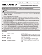
Wiring
Diagram
Wiring
Diagram
S
1
2
3
J1
Core-S
Input
Harness
J11
1
2
3
SHIELD
BLACK
RED
123
Mic.
Extension
Cable
Common
Normally Open
Normally Closed
Shield
CAN L
CAN H
Speaker 2 (Howler™) (+)
Speaker 2 (Howler™) (-)
Speaker 1 (+)
Speaker 1 (-)
High Current Output 4
High Current Output 1
High Current Output 3
High Current Output 2
Cabin Speaker (+)
Radio (+)
AUX Input (+)
Cabin Speaker (-)
Radio (-)
AUX Input (-)
4
WHT/YEL Digital Input (4)
7
BROWN Analog Input (1)
6
WHT/BLU Digital Input (6)
5
WHT/GRN Digital Input (5)
2
WHT/RED Digital Input (2)
3
WHT/ORG Digital Input (3)
1
WHT/BRN Digital Input (1)
8
RED Analog Input (2)
9
ORANGE Analog Input (3)
10
YELLOW Analog Input (4)
12
RED/WHT Ignition
4
YELLOW Low Current Output (4)
7
VIOLET Low Current Output (7)
6
BLUE Low Current Output (6)
5
GREEN Low Current Output (5)
2
RED Low Current Output (2)
3
ORANGE Low Current Output (3)
1
BROWN Low Current Output (1)
8
GREY Low Current Output (8)
9
WHT/BRN Low Current Output (9)
10
WHT/RED Low Current Output (10)
11
WHT/ORG
Low Current Output (11)
12
WHT/YEL
Low Current Output (12)
1
2
3
4
5
6
7
8
9
1
0
1
2
J9
C
ore-
S
I
n
p
u
t
Ha
rn
ess
4
W
HT/YE
L
Di
g
ital Input (4
)
7
B
ROWN Analo
g
Input (1
)
6
W
HT
/
BLU Di
g
ita
l
Input (6
)
5
W
HT/GR
N
Di
g
ita
l
Input (5
)
2
WHT/RED
Di
g
ital Input (2
)
3
W
HT/ORG Di
g
ital Input (3
)
1
W
HT
/
BRN Di
g
ital Input (1
)
8
RE
D
Analog Input (2
)
9
O
RANG
E
Analo
g
Input (3
)
1
0
YELLOW Analo
g
Input (4
)
1
2
T
RED/WHT
T
Ig
nitio
n
R
E
D
BR
O
W
N
ORANGEORANGE
1
2
3
1
2
3
D
r
y
C
ontact
R
e
l
ay
J3
C
o
mm
on
Normall
y
Open
Norma
ll
y C
l
ose
d
1
1
2
2
3
4
4
2
G
REY
1
O
RANG
E
4
YELLOW
YELLOW
YELLOW
3
BR
O
W
N
4
Pos.
MU
MN
L
J
1
S
p
ea
k
er 2 (How
l
er™) (+
)
Spea
k
er 2 (How
l
er™) (-
)
S
p
ea
k
er 1 (+)
S
p
ea
k
er 1 (-
)
RED
J11
1
2
3
SHIELDSHIELD
B
LA
C
K
RED
D
1
2
3
M
i
c.
E
xtensio
n
C
abl
e

Page 9
J10--1 BLU - RADIO (+)
2 - - (-)BLU RADIOJ15-
3 - (+)WHT/YEL CAB SPKRJ15-
4 - (+)GRN - AUX INJ15-
5 - (-)GRN - AUX INJ15-
6 - YEL - (-)CAB SPKRJ15-
- 1 BRN - Normally OpenJ3 -
2 - RED - Common
3 - ORG - Normally ClosedJ17 -
J14 - 1 - BRN - HC Output 1
2 - RED - HC Output 2J17 -
3 - ORG - HC Output 3J17 -
4 - YEL - HC Output 4J17 -
- 1 - BRN - LC Output 1J15
2 - RED - LC Output 2J14 -
3 - ORG - LC Output 3J14 -
4 - YEL - LC Output 4J14 -
5 - GRN - LC Output 5J14 -
6 - BLU - LC Output 6J14 -
7 - VIO - LC Output 7
8 - GRY - LC Output 8J14 -
9 - WHT/BRN - LC Output 9J14 -
10 - WHT/RED - LC Output 10J14 -
11 - WHT/ORG - LC Output 11J14 -
12 - WHT/YEL - LC Output 12J14 -
- 1 - WHT/BRN - Dig. Input 1J9
2 - WHT/RED - Dig. Input 2J14 -
3 - WHT/ORG - Dig. Input 3J14 -
4 - WHT/YEL - Dig. Input 4J14 -
5 - WHT/GRN - Dig. Input 5J14 -
6 - WHT/BLU - Dig. Input 6J14 -
7 - BRN - Analog Input 1
8 - RED - Analog Input 2J10 -
9 - ORG - Analog Input 3J10 -
10 - YEL- Analog Input 4J10 -
11 - N/AJ10 -
12 - RED/WHT - IgnitionJ10 -
This worksheet has been provided
so that a written record of all Input,
Output and Axillary connections may
be created. After all data has been
verified and recorded, store and
retain this sheet for future reference.
It is recommended that you make a
copy of this worksheet before filling in.
so that if any changes need to be
made you will have a blank copy.
CONNECTOR - PIN FUNCTION- ASSIGNED TO:
Cencom™ Core-S™
Installation Worksheet
/