Page is loading ...

For warranty information regarding this product, visit www.whelen.com/warranty
©20 Whelen Engineering Company Inc.21
Form No. 1 A ( )4D48 010821
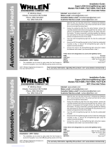
700-series - (B/T/T, Turn Signal, Back-Up)
Installation:
IMPORTANT NOTICE! This product has been designed for improved visibility.
Prior to installing this product on any vehicle, check you state motor vehicle
codes to confirm that this product complies with any and all state statutes
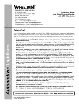
1. Using the dimensions shown, drill two, 5/16” diameter vent tube holes
and a 1” wire hole into the mounting surface.
2. Place the lighthead into position and mark off the 4 mounting holes. Using
a 1/4” drill bit, drill the 4 mounting holes. Install a grommet (customer
supplied) into the 1” wire hole.
3. Using appropriately sized wires (Min. 18 AWG), extend the wires to their
connections. Fuse the connections at 3 Amps and test the(+) 10-30V
lighthead for proper operation. Secure the lighthead to the vehicle using
the flange grommet and the four #6 x 1-1/2” sheet metal screws.
1.187
2.375
6.562
1.68
.84
1/4" Mtg. Hole
(4 Places)
1” Dia. Hole
.313 Dia. Hole
(2) Places
Safety First: This document provides all the necessary information to allow your Whelen product to be properly and safely installed. Before beginning the installation
and/or operation of your new product, the installation technician and operator must read this manual completely. Important information is contained herein that could
prevent serious injury or damage.
• Whelen Engineering requires the use of waterproof butt splices and/or
connectors if that connector could be exposed to moisture.
• Any holes, either created or utilized by this product, should be made both
air- and watertight using a sealant recommended by your vehicle
manufacturer.
• Failure to use specified installation parts and/or hardware will void the
product warranty!
• If mounting this product requires drilling holes, the installer MUST be
sure that no vehicle components or other vital parts could be damaged by
the drilling process. e-burr any holes and remove any metal shards orD
remnants. Install grommets into all wire passage holes.
• Do not install this product or route any wires in the deployment area of
your air bag. Equipment mounted or located in the air bag deployment
area will damage or reduce the effectiveness of the air bag, or become a
projectile that could cause serious personal injury or death. Refer to your
vehicle owner's manual for the air bag deployment area. The
User/Installer assumes full responsibility to determine proper mounting
location, based on ultimate safety to all passengers inside thethe
vehicle.
• For this product to operate at optimum efficiency, a good electrical
connection to chassis ground must be made. The recommended
procedure requires the product ground wire to be connected directly to
the NEGATIVE (-) battery post.
• If this product uses a remote device to activate or control this product,
make sure that this control is located in an area that allows both the
vehicle and the control to be operated safely in any driving condition.
• Do not attempt to activate or control this device in a hazardous driving
situation.
• This product contains either strobe light(s), halogen light(s), high-
intensity LEDs or a combination of these lights. Do not stare directly into
these lights. Momentary blindness and/or eye damage could result.
• Use only soap and water to clean the outer lens. Use of other chemicals
could result in premature lens cracking (crazing) and discoloration.
Lenses in this condition have significantly reduced effectiveness and
should be replaced immediately. Inspect and operate this product
regularly to confirm its proper operation and mounting condition. Do not
use a pressure washer to clean this product.
•WARNING! All customer supplied wires that connect to the positive (+)
terminal of the battery must be sized to supply at least 125% of the
maximum operating current and “at the battery” to carry that load.FUSED
DO NOT USE CIRCUIT BREAKERS WITH THIS PRODUCT!
• FAILURE TO FOLLOW THESE PRECAUTIONS AND INSTRUCTIONS
COULD RESULT IN DAMAGE TO THE PRODUCT OR VEHICLE AND/OR
SERIOUS INJURY TO YOU AND YOUR PASSENGERS!
51 Winthrop Road
Chester, Connecticut 06412-0684
Phone: (860) 526-9504
Sales Email:[email protected]
Canadian Sales:[email protected]
Customer Service:[email protected]
B/T/T
3 POS DEUTSCH SOCKET
POS. A - BROWN
POS. B - YELLOW
POS. C - WHITE
AMP 3 POS PIN
POS 1 - BROWN
POS 2 - YELLOW
POS 3 - WHITE
BACK-UP
3 POS DEUTSCH SOCKET
POS. A - WHITE
POS. B - N/C
POS. C - BLACK
AMP 3 POS PIN
POS 1 - WHITE
POS 2 - N/C
POS 3 - BLACK
TURN SIGNAL
3 POS DEUTSCH SOCKET
POS. A - ORANGE
POS. B - N/C
POS. C - BLACK
CAP - WHT/VIO
AMP 3 POS PIN
POS 1 - ORANGE
POS 2 - N/C
POS 3 - BLACK
CAP - WHT/VIO
Wiring:
Back-Up Model
Connect WHT wire to output wire of the back-up light circuit.(+) 10-30V
Connect BLK wire to GROUND.
B/T/T Model
Connect YEL wire to (+) 10-30V output wire of brake light circuit.
Connect BRN wire to (+) 10-30V output wire of the taillight circuit.
Connect WHT wire to GROUND.
Turn Signal Model
Connect ORG wire to (+)10-30V output wire of the turn signal circuit.
Connect BLK wire to GROUND.
Connect WHT/VIO wire to to a momentary switch and extend the wire to (+)10-30V. Fuse
wire @ 1 Amp.
TURN SIGNAL Model
CAUTION! NOT LOOK DIRECTLY AT THESE LE THEY ARE ON.DO Ds WHILE
MOMENTARY BLINDNESS AND/OR EYE DAM E COULD RESULT!AG
IM ORTANT WARNING!P
®
www. .com
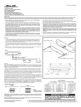
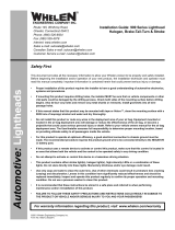
WIRING DIAGRAM
(B/T/T)
Back-Up
(Turn Signal)
Back-Up (+)- Positive
Ground
WHITE
BLACK
3Amp
Brake - Positive (+)
Tail - Positive (+)
Ground
YELLOW
BROWN
WHITE
3Amp
3Amp
(+) 10-30V
Turn Positive (+)-
Ground
WHT/VIO
1Amp
3Amp
Momentary
witchS
BLACK
ORG
IMPORTANT! Ensure that Back-Up, B/T/T and Turn Signal Lightheads are
fused at 3 AMPS either through OEM fusing or customer supplied fuse.
1. Steady On (Arrow)
Sequence (80 FPM)2.
to Solid2.
Flashing Arrow (80 FPM)3.
4. Flashing Solid (80 FPM)
Sequence (120 FPM)5.
to Solid
6. Flashing Arrow (120 FPM)
Flashing Solid (120 FPM)7.
Sequence to Solid (Slow)8.
Steady On
9. Sequence to Solid (Fast)
Steady On
Steady On (Solid)10.
WHITE/VIO - ScanLock™ Pattern Selection: This feature allows the user to select from
several available flash patterns. Lighthead must be powered on for Scan-Lock to work.
TO CYCLE THROUGH ALL PATTERNS: Apply (+) 10-30V to the WHT/ VIO wire for less
than 1 second and release. To cycle backward, apply (+) 10-30V to the WHT/VIO wire for
over 1 second and release.
TO SET A PATTERN AS DEFAULT: Allow the pattern to run for more than 5 seconds. The
lighthead will now display this pattern when active.
TO RESET TO THE FACTORY DEFAULT PATTERN: Turn off power. While applying (+)
10-30V to the
WHT/VIO wire, turn power on. The lighthead will reset to its default pattern.
/