Page is loading ...

Page 1
Installation Guide:
UPS64LXA Strobe Power Supply
©2003 Whelen Engineering Company Inc.
Form No.13840A (072507)
®
ENGINEERING COMPANY INC.
51 Winthrop Road
Chester, Connecticut 06412-0684
Phone: (860) 526-9504
Fax: (860) 526-4078
Internet: www.whelen.com
Sales e-mail: autosale@whelen.com
Canadian Sales e-mail: autocan@whelen.com
Customer Service e-mail: custserv@whelen.com
Automotive: Power Supplies
Safety First
This document provides all the necessary information to allow your Whelen product to be properly and safely installed.
Before beginning the installation and/or operation of your new product, the installation technician and operator must
read this manual completely. Important information is contained herein that could prevent serious injury or damage.
• Proper installation of this product requires the installer to have a good understanding of automotive
electronics, systems and procedures.
• If mounting this product requires drilling holes, the installer MUST be sure that no vehicle components or
other vital parts could be damaged by the drilling process. Check both sides of the mounting surface
before drilling begins. Also de-burr any holes and remove any metal shards or remnants. Install grommets
into all wire passage holes.
• If this manual states that this product may be mounted with suction cups, magnets, tape or Velcro®, clean
the mounting surface with a 50/50 mix of isopropyl alcohol and water and dry thoroughly.
• Do not install this product or route any wires in the deployment area of your air bag. Equipment mounted
or located in the air bag deployment area will damage or reduce the effectiveness of the air bag, or
become a projectile that could cause serious personal injury or death. Refer to your vehicle owner’s
manual for the air bag deployment area. The User/Installer assumes full responsibility to determine proper
mounting location, based on providing ultimate safety to all passengers inside the vehicle.
• For this product to operate at optimum efficiency, a good electrical connection to chassis ground must be
made. The recommended procedure requires the product ground wire to be connected directly to the
NEGATIVE (-) battery post.
• If this product uses a remote device to activate or control this product, make sure that this control is
located in an area that allows both the vehicle and the control to be operated safely in any driving
condition.
• Do not attempt to activate or control this device in a hazardous driving situation.
• It is recommended that these instructions be stored in a safe place and referred to when performing
maintenance and/or reinstallation of this product.
• FAILURE TO FOLLOW THESE SAFETY PRECAUTIONS AND INSTRUCTIONS COULD RESULT IN DAMAGE
TO THE PRODUCT OR VEHICLE AND/OR SERIOUS INJURY TO YOU AND YOUR PASSENGERS!
For warranty information regarding this product, visit www.whelen.com/warranty

Page 2
1
2
3
3
2
3
2
1
Switch
(see note)
BATTERY
FUSE
(CUSTOMER SUPPLIED)
15 AMP FUSE FOR 12V
7.5 AMP FUSE FOR 24V
RED
BLACK
VIOLET
GREEN
BLUE Switch 2
Switch2-Outlets2&3
Switch3-Outlets1&4 Switch 3
Switch 1
GREY
WHITE/VIO
WHITE/RED
ALTERNATING
1
2
3
4
OUTLETS
Scan/SyncControlPower
Selecting a mounting location...
The most common choice for a mounting area would be a trunk or similar
compartment. However, due to the wide variety of vehicles onto which the
UPS64LXA could be installed, this is not always possible. The following guidelines
will help determine an acceptable alternative:
• The unit should be mounted on a metal surface to aid heat dissipation. Be
sure that this surface is not one that either generates or is exposed to
excessive heat during normal operation of the vehicle.
• Do not select a location where the unit will be exposed to potential
damage from any unsecured or loose equipment in the vehicle.
• Be sure the area selected will not allow the unit to be exposed to water!
• When routing wires, it is important to choose a path that will keep these
wires away from excessive heat and from any vehicle equipment that
could compromise the integrity of the wires (ex. trunk lids, door jams,
etc.).
• When the best mounting location has been determined, securely fasten
the unit to its mounting surface using the supplied hardware.
WARNING: The Strobe Light Power Supply is a high voltage device.
Do not touch or remove tube assembly in strobe light head assem-
blies while in operation. Wait 10 minutes after disconnecting the unit
from its power source before starting work or troubleshooting on
power supply or system.
1. Position the unit in its proposed mounting location to ensure that it fits properly.
With the unit in place, insert an awl or other suitable tool into the mounting
screw area of the power supply and scribe the areas that are to be drilled.
2. Remove the unit from its mounting area and, using a drill bit sized for a #10
sheet metal screw, drill a hole in each of the areas scribed in the previous step.
3. Return the unit to its mounting location. Using the supplied #10 sheet metal
screws, secure it onto its mounting surface.
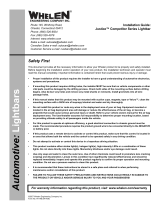
Wiring ...
1. Locate the 3-position Power Connector included with your power supply and
plug it into the port indicated in Fig. 1. Extend the BLACK and RED wires
towards the battery.
WARNING! All customer supplied wires that connect to the positive terminal
of the battery must be sized to supply at least 125% of the maximum operating
current and FUSED at the battery to carry that load. DO NOT USE CIRCUIT
BREAKERS WITH THIS PRODUCT!
2. Connect the RED wire to a fuse block (customer supplied) and then to the
POSITIVE terminal on the battery.
NOTE! Although a fuse (customer supplied) is required to be used in the fuse
block, do not install the fuse until all of the wire connections are completed.
3. Connect the BLACK wire to the factory chassis ground adjacent to the battery.
4. Refer to Fig. 2 for wiring information for the Control Connector and for the
Scan/Sync Connector.
5. As indicated in Fig. 2, there is a provision in the Power Connector for a wire
(VIOLET) to activate Hi/Low Power strobe operation. If this feature is desired,
locate the VIOLET wire included with your power supply and, with the Power
Connector disconnected from the power supply, insert the pinned end of the
VIOLET wire into position 3 of the Power Connector. Refer to Fig. 2 for wiring
information.
Scan-Lock™ Operation...
To cycle through all patterns: Apply +12VDC to the WHT/VIO wire for less than 1
second and release to cycle forward.
Apply +12VDC for more than 1 second and release to cycle backward.
To set a pattern as Default: When the desired pattern is displayed, allow it to run for
more than 5 seconds. The lightheads will now display this pattern when active.
To reset to the Factory Default pattern: Turn off power. While applying +12VDC to
the WHT/VIO wire, turn power back on.
Available Scan-Lock™ Patterns (in order) -
1) CometFlash® 6) ModuFlash™
2) TripleFlash™ 7) MicroBurst II™
3) DoubleFlash 8) MicroBurst III™
4) RapidRate™ 9) LongBurst™
5) ActionFlash™ 10) ActionScan™
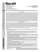
Sync Operation...
NOTE! Synchronized power supplies should be configured to flash the same
pattern.
The GREY wire is used when synchronizing two (or more) UPS64LXA power
supplies. When synchronized, all strobes connected to outlets 1 & 3 on their
respective power supplies will alternate with all strobes connected to outlets 2 & 4 on
their respective power supplies.
Strobe Outlets*
*Outlets1&3alternate
with outlets2&4*
Outlet
Control Power
Control
Fuse
(15A)
Scan / Sync
Control
1234
-15-
NOTE - The type of switch used is dependant on how the operator wishes the
Hi/Low feature to function:
Latching Mode:
By applying +voltage to the Violet wire for less than 1 sec., the power supply
is “latched” into low power operation. The unit must be turned off and then back
on to restore normal, Hi power operation. A momentary switch is desired for
this style.
Level Mode:
Applying +voltage to the Violet wire for more than 1 sec. holds the power
supply in low power mode until that voltage is removed. A toggle switch is
desired for this style.
Fig. 1
Fig. 2
UPS64LXA SPECIFICATIONS:
INPUT VOLTAGE - 13.5 VDC (26.5 VDC) ± 20%
INPUT CURRENT @ 4 LAMPS - 7 AMPS (4AMPS)
INPUT CURRENT @ 2 LAMPS - 4 AMPS (2.5 AMPS)
OUTPUT POWER @ 4 LAMPS - 75 Watts
OUTPUT POWER @ 2 LAMPS - 40 Watts
V Ctrl - 13.5 VDC (26.5 VDC) ± 20%
I Ctrl - 100 ma (MAX)
V Output Ctrl - 13.5 VDC (26.5 VDC) ± 20%
I Output Ctrl - 20 ma (MAX)
V Pattern Ctrl - 13.5 VDC (26.5 VDC) ± 20%
I Pattern Ctrl - 5 (MAX)
/