Page is loading ...

WorkSide Light
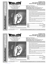
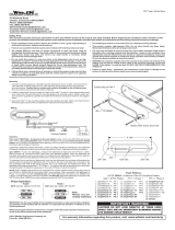
Mounting:
1. Mark the location of the 2 mounting holes onto the mounting
surface using the dimensions shown, or use the flange as a
template. Always check behind the mounting surface to be sure
you will not harm other vehicle components.
2. Drill the 2 mounting holes using a drill sized for a #6 sheet metal
screw, then drill the 1” wire access hole as shown. Deburr this hole
before continuing.
3. Feed wires through wire hole then secure WorkSide Light to
mounting surface as shown.
IMPORTANT! Proper installation requires the vent membrane to
be located above the horizontal centerline of the installed
WorkSide Light!
Scan-Lock™:
TO CHANGE RAMP ON SETTING: To cycle forward to the next ramp on
setting apply +VBAT to the WHT/VIO wire (or switch) for less than 1 second
and release. To cycle back to the previous ramp on setting, apply +VBAT to
WHT/VIO wire for over 1 second and release. When cycling through options,
the unit will demonstrate the ramp on speed and then save it. A quick flash
indicates ramp on is turned OFF and the unit is set to power on at full
brightness instantly.
TO RESTORE THE FACTORY DEFAULT RAMP ON SETTING: With the unit
turned off, apply power to the WHT/VIO wire, then turn on the unit. The unit will
turn on with its current setting and then reset to default (SLOW 800ms) for
subsequent power on. Allow the unit to run for 3 seconds before removing
power from the WHT/VIO wire.
TO CHANGE LOW POWER INTENSITY: Apply +VBAT to the VIO wire to hold
in low power mode. Cycle forward to the next intensity by applying +VBAT to
the WHT/VIO wire (or switch) for less than 1 second and releasing. To cycle
back to the previous intensity, apply +VBAT to WHT/VIO wire for over 1 second
and release. The intensity will be saved 1 second after the switch.
TO RESTORE THE FACTORY DEFAULT LOW POWER INTENSITY: With the
unit turned off, apply power to the WHT/VIO wire and the VIO wire, then turn
on the unit. The unit will turn on with low power active with its current intensity
and then reset to default (25%) for subsequent low power operation. Allow the
unit to run for 3 seconds before removing power from the WHT/VIO wire.
Electrical Specifications:
Current: 12V - 1.40A | 25.6V - 0.75A
For warranty information regarding this product, visit www.whelen.com/warranty
©2023 Whelen Engineering Company Inc.
Form No. 14F32 (060623)
CAUTION! DO NOT LOOK DIRECTLY AT THESE LEDS WHILE THEY ARE ON.
MOMENTARY BLINDNESS AND/OR EYE DAMAGE COULD RESULT!
IMPORTANT WARNING! It is the responsibility of the installation technician to make sure that the installation
and operation of this product will not interfere with or compromise the operation or
efficiency of any vehicle equipment!
Before returning the vehicle to active service, visually confirm the proper operation of
this product, as well as all vehicle components/equipment.
Safety First: This document provides all the necessary information to allow your Whelen product to be properly and safely installed. Before beginning the installation
and/or operation of your new product, the installation technician and operator must read this manual completely. Important information is contained herein that could
prevent serious injury or damage.
• Proper installation of this product requires the installer to have a good understanding of
automotive electronics, systems and procedures.
• Whelen Engineering requires the use of waterproof butt splices and/or connectors if that
connector could be exposed to moisture.
• Failure to use specified installation parts and/or hardware will void the product warranty!
• If mounting this product requires drilling holes, the installer MUST be sure that no vehicle
components or other vital parts could be damaged by the drilling process. Check both
sides of the mounting surface before drilling begins. Also de-burr any holes and remove
any metal shards or remnants. Install grommets into all wire passage holes.
• Do not install this product or route any wires in the deployment area of your air bag.
Equipment mounted or located in the air bag deployment area will damage or reduce the
effectiveness of the air bag, or become a projectile that could cause serious personal
injury or death. Refer to your vehicle owner's manual for the air bag deployment area. The
User/Installer assumes full responsibility to determine proper mounting location, based
on providing ultimate safety to all passengers inside the vehicle.
• For this product to operate at optimum efficiency, a good electrical connection to chassis
ground must be made. The recommended procedure requires the product ground wire to
be connected directly to the NEGATIVE (-) battery post.
• If this product uses a remote device to activate or control this product, make sure that this
control is located in an area that allows both the vehicle and the control to be operated
safely in any driving condition.
• Do not attempt to activate or control this device in a hazardous driving situation.
• This product contains either strobe light(s), halogen light(s), high-intensity LEDs or a
combination of these lights. Do not stare directly into these lights. Momentary blindness
and/or eye damage could result.
• Waterproof butt splices and/or connectors are required if that connection could be
exposed to moisture. Any unused wires must be sealed (waterproofed) to prevent
moisture infiltration.
• WARNING! All customer supplied wires that connect to the positive (+) terminal of the
battery must be sized to supply at least 125% of the maximum operating current and
FUSED “at the battery” to carry that load. DO NOT USE CIRCUIT BREAKERS WITH THIS
PRODUCT!
• FAILURE TO FOLLOW THESE PRECAUTIONS AND INSTRUCTIONS COULD RESULT IN
DAMAGE TO THE PRODUCT OR VEHICLE AND/OR SERIOUS INJURY TO YOU AND YOUR
PASSENGERS!
.1" Dia. Vent
Membrane
Horizontal
Centerline
13.40”
14”
6.70”
Flat
Washer
Mounting Style #1
Mounting Style #2 (Hardware Not Included)
Split
Lockwasher
Nut
Flange
Flange
Gasket
Gasket
#6 x 1”
Sheet Metal Screw
#6 x 1 1/4
Machine Screw
®
ENGINEERING COMPANY INC.
51 Winthrop Road
Chester, Connecticut 06412-0684
Phone: (860) 526-9504
Sales Email:[email protected]
Canadian Sales:[email protected]
Customer Service:[email protected]
www. .com
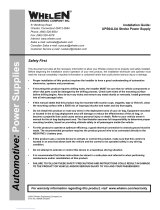
DVI / Low Power Scan-Lock Table
Num DVI Ramp Up Speed
1
2
3
4
Slow Ramp
Medium Ramp
Fast Ramp
Instant On
25%
50%
75%
NA
Low Power
800ms
400ms
200ms
Num
1
2
3
4
2.63”
Wire Color
White
Black
Function
(+) 12V or 24V (Fuse@3A)
(-) Ground
Violet Low Power
White W/ Violet Scan-Lock
/