Page 2
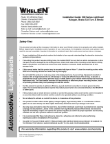
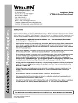
Lighthead mounting holes, fit onto raised bosses on mounting bracket.
LED LIGHTHEAD
STROBE
LIGHTHEAD
Clips on bracket snap
over edge of lighthead.
Fig. 4
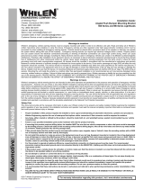
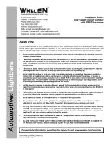
Rotator base
sits on tape
Rotator Removal and Installation
Rotator base
sits on tape
Tape
Fastex
Grommet
Side View
TAPE
Fig. 3
Screws thread into fastex grommet
that is inserted into base.
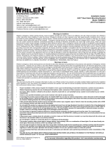
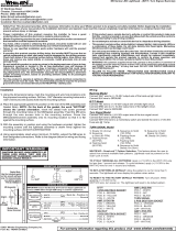
Removal and
Installation of Lens
and Lenscap
Fig. 2
Fastex grommet
snaps into bracket.
(
Do not remove
)
Remove screws
from end of lenscap
Remove screws and lens
retainer, then remove
lens or lenscap
IMPORTANT! The lightbar should be located a minimum of 16" from any radio
antennas!
Installation:
Note: When routing wires, it is important to choose a path that will keep them away from
excessive heat or any vehicle equipment that could compromise the wires integrity.
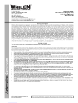
1. This lightbar attaches to the vehicle by 1-1/4” bolts extending from the rear of the housing. Position the unit in its
proposed mounting location to ensure that it fits properly. With the lightbar in place, use an awl or other suitable
tool and scribe the areas to be drilled (Fig. 1).
2. Remove the lightbar and, using an appropriately sized drill bit, drill a hole in each of the areas scribed in step 1,
than return the lightbar to its mounting location and using the supplied hardware, secure it to the vehicle.
Wiring:
Extend the control wires to your switch panel and make the appropriate connections using the
wiring information provided in this manual. Read all warnings before installing this lightbar.
IMPORTANT! All Positive (+) input wires must be individually fused. Due to the large number of
possible configurations, each with their own fusing requirements, it is the installation
technician's responsibility to determine the maximum current draw for each input wire and to
fuse that wire at 125% of that value.
Servicing your lightbar:
NOTE: Before opening your lightbar for service or repair always be sure to Disconnect the
lightbar from it’s power source. (See strobe light warning below.)
Lens or Lenscap: Removal or Installation
To remove a lenscap, remove the 2 screws from the end of the lenscap, and the 2 screws from the opposite side that
thread through the lens retainer into the lighthead mounting bracket. Pull the lenscap off (Fig. 2).
To remove a lens, remove the 4 phillips head screws that thread
through the lens retainer into the lighthead mounting bracket and
then pull the lens off.
Removing an Existing Rotator:
1. Disconnect the lightbar from power. For lightbars with strobe lights, wait a minimum of 10 minutes before proceeding.
2. Remove the lens or lenscap in front of the rotator you wish to replace.
3. Disconnect the rotator from the lightbar’s harness by unplugging the Amp 2 position pin connector. NOTE: It is easier
to remove the existing rotator from the extrusion if the reflector is facing the front of the lightbar (Fig. 3).
4. Using a phillips head screwdriver, loosen the two screws that secure the rotator base to the extrusion (2 or 3 turns).
5. Lift the rear of the rotator base then remove the rotator from the extrusion.
Installation of a New Rotator:
1. Remove any adhesive tape on the lightbar base left from the old rotator.
2. Remove the backing from the piece of 2-sided tape and apply it to the lightbar base in the same location as the
previous tape (Fig. 3).
3. Plug the new rotator into the old rotator’s harness plug.
4. Place the new rotator inside the extrusion in the same area the old rotator was removed from but don’t tighten the
screws yet.
5. Remove the backing from the tape and press the rotator base down onto the lightbar base firmly, being careful not
pinch any wires between the base and extrusion, then tighten the mounting screws.
6. Reconnect lightbar to power and test for proper operation then return any lenscaps or lenses you had to remove.
Servicing Lightheads: Strobe, Halogen or LED WARNING: The strobe light power supply is a high voltage device. Do
not touch or remove the strobe tube assembly while in operation.
Wait 10 minutes after disconnecting the unit from its power source
before starting any work or trouble shooting.
Removal and Installation
1. Disconnect the lightbar from it’s power source.
2. To remove the lighthead, first remove the lens or lenscap necessary to access
the lighthead you wish to service or replace.
3. Now pull the clips back on the mounting bracket that secure the lighthead as
you lift the lighthead off of the raised bosses on the bracket (Fig. 4).
4. Being careful not to pull out any wires, lift the lighthead out of the lightbar base,
disconnect its connector from the lightbar wiring harness, then lift the lighthead
out of the lightbar.
5. To reinstall the lighthead, plug the lightheads connector into the lightbar, snap it
back into the brackets and replace any lenses or lenscaps you had to remove.
WARNING: All Customer supplied wires that connect to the positive terminal of the battery must be sized to supply at least 125% of the
maximum operating current and FUSED at the battery to carry that load. DO NOT USE CIRCUIT BREAKERS WITH THIS PRODUCT!
STEP BOLT
Fig. 1
Mounting the Lightbar
to the vehicle
3/8" X 16 HEX NUT
3/8" LOCKWASHER
3/8" FLATWASHER