Page is loading ...

ION T-Series™ Super-LED® Light
For warranty information regarding this product, visit www.whelen.com/warranty
©2023 Whelen Engineering Company Inc.
Form No. 14F43 (022223)
Mounting
IMPORTANT! BEFORE MOUNTING READ ALL THE ABOVE WARNINGS FOR
MOUNTING, VEHICLE DAMAGE AND WIRE ROUTING.
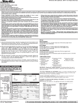
Ground (BLK) - Extend the BLK wire to Chassis Ground.
Warning Light (LED Color) - Extend the LED wire to +VBAT via an SP/ST switch.
Fuse @ 3 AMPS.
SYNC (GREY) - To SYNC 2 lightheads, configure both lightheads to display the
same Phase 1 (Simultaneous) pattern. Turn power off and connect the GREY wire
from each lighthead together. Activate the lightheads and their patterns will be
synchronized. To configure 2 lightheads to alternate their patterns, advance
either lighthead to Phase 2 (Alternating) of the current pattern.
Scan-Lock™ (WHT/VIO) - Extend the WHT/VIO wire to +VBAT via a momentary
switch (fuse @ 1 amp).
Steady-Lock™ - When connected to a Core™ control system, a lighthead doesn't
require manually scanlocking to the steady pattern. All populated outputs can be sent
a Steady-Lock™ signal from Whelen Command®, automatically setting their pattern
to Steady. A minimum Whelen Command® version of 2.2.9 is required for this
Steady-Lock™ feature.
Scan-Lock Operation
Note: In order to change flash patterns, the lighthead must be on.
TO CHANGE PATTERNS: To advance to the next pattern apply +VDC to the
WHT/VIO wire for less than 1 second and release. To cycle back to the previous
pattern apply +VDC to the WHT/VIO wire for more than 1 second and release.
TO CHANGE THE DEFAULT PATTERN: When the desired pattern is displayed,
allow it to run for more than 5 seconds. The lighthead will now display this pattern
when initially activated.
TO RESTORE THE FACTORY DEFAULT PATTERN: This will reset all patterns
back to their default settings. With the light turned off, apply power to the WHT/VIO
wire. With power applied to the WHT/VIO wire, turn light on. Allow the unit to run for
3 seconds before removing power from the WHT/VIO wire.
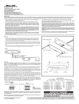
Flash Patterns
Hardware Mount
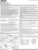
1. Using the mounting dimensions shown, mark the mounting and wire hole
locations onto the proposed mounting surface.
2. Drill two mounting holes (sized for #6 sheet metal screws and the mounting
surface thickness) and a 1/2" wire passage hole into the mounting surface.
De-burr wire passage hole before proceeding.
3. Route the lighthead wires through the wire passage hole. Position the
ION™ onto its mounting location and place the mounting flange onto the
Micron as shown.
4. Insert the two supplied #6 sheet metal screws through the flange mounting
holes and into the mounting surface. Tighten the mounting screws until the
lighthead assembly is drawn firmly against the mounting surface.
5. Using appropriately sized wires (minimum 22 AWG), extend the wires to
their designated connections. Refer to the Wiring Diagram for wiring and
fusing information.
LED Color
BLK (12V Models)
GRY
ION T Series
WHT/VIO Scan-Lock
SP/ST Switch Fuse
(3A)
Sync
(+)
Battery
(-)
ALL SWITCHES AND FUSES
ARE CUSTOMER SUPPLIED
Wiring Diagram
®
ENGINEERING COMPANY INC.
51 Winthrop Road
Chester, Connecticut 06412-0684
Phone: (860) 526-9504
Fax: (860) 526-4078
Sales Email:[email protected]
Canadian Sales:[email protected]
Customer Service:[email protected]
www. .com
Safety First: This document provides all the necessary information to allow your Whelen product to be properly and safely installed. Before beginning the installation
and/or operation of your new product, the installation technician and operator must read this manual completely. Important information is contained herein that could
prevent serious injury or damage.
• Proper installation of this product requires the installer to have a good understanding of
automotive electronics, systems and procedures.
• Whelen Engineering requires the use of waterproof butt splices and/or connectors if that
connector could be exposed to moisture.
• Failure to use specified installation parts and/or hardware will void the product warranty!
• If mounting this product requires drilling holes, the installer MUST be sure that no vehicle
components or other vital parts could be damaged by the drilling process. Check both
sides of the mounting surface before drilling begins. Also de-burr any holes and remove
any metal shards or remnants. Install grommets into all wire passage holes.
• Do not install this product or route any wires in the deployment area of your air bag.
Equipment mounted or located in the air bag deployment area will damage or reduce the
effectiveness of the air bag, or become a projectile that could cause serious personal
injury or death. Refer to your vehicle owner's manual for the air bag deployment area. The
User/Installer assumes full responsibility to determine proper mounting location, based
on providing ultimate safety to all passengers inside the vehicle.
• For this product to operate at optimum efficiency, a good electrical connection to chassis
ground must be made. The recommended procedure requires the product ground wire to
be connected directly to the NEGATIVE (-) battery post.
• If this product uses a remote device to activate or control this product, make sure that this
control is located in an area that allows both the vehicle and the control to be operated
safely in any driving condition.
• Do not attempt to activate or control this device in a hazardous driving situation.
• This product contains either strobe light(s), halogen light(s), high-intensity LEDs or a
combination of these lights. Do not stare directly into these lights. Momentary blindness
and/or eye damage could result.
• Waterproof butt splices and/or connectors are required if that connection could be
exposed to moisture. Any unused wires must be sealed (waterproofed) to prevent
moisture infiltration.
• WARNING! All customer supplied wires that connect to the positive (+) terminal of the
battery must be sized to supply at least 125% of the maximum operating current and
FUSED “at the battery” to carry that load. DO NOT USE CIRCUIT BREAKERS WITH THIS
PRODUCT!
• FAILURE TO FOLLOW THESE PRECAUTIONS AND INSTRUCTIONS COULD RESULT IN
DAMAGE TO THE PRODUCT OR VEHICLE AND/OR SERIOUS INJURY TO YOU AND YOUR
PASSENGERS!
4.44”
Mounting Pattern
.500 dia. Holes sized for #6
Sheet Metal Screw
ION T-series™
Mounting
Flange
#6 x 3/4
PPHSMS
Gasket
SignalAlert™ 75 PH1
SignalAlert™ 75 Ph2
CometFlash 75 Ph1
CometFlash 75 Ph2
ComAlert™ 75 Ph1
ComAlert™ 75 PH2
LongBurst™ 75 PH1
LongBurst™ 75 PH2
PingPong™ 75 PH1
PingPong™ 75 PH2
SingleFlash 75 PH1
SingleFlash 75 PH2
DoubleFlash 75 PH1
DoubleFlash 75 PH2
Tripleflash™ 75 PH1
Tripleflash™ 75 PH2
SingleFlash 60
Pattern# Pattern#
Name Name
Cert. Cert.
SingleFlash 90
SingleFlash 120
SingleFlash 240
DoubleFlash 120
Tripleflash™ 120
ComAlert™ 150
PingPong™ 120
ActionFlash™ 60
ActionFlash™ 120
Action SF 60/120
Action SF120/TF75
ModuFlash
CalScan
ActionScan
SigAlert STEADY
STEADY
1.
2.
3.
4.
5.
6.
7.
8.
9.
10.
11.
12.
13.
14.
15.
16.
17.
18.
19.
20.
21.
22.
23.
24.
25.
26.
27.
28.
29.
30.
31.
32.
33.
1,2,3,4
1,2,3,4
1,2,3,4
1,2,3,4
1,2,3,4
1,2,3,4
1,2,3,4
1,2,3,4
1,2,3,4
1,2,3,4
1,2,3,4
1,2,3,4
1,2,3,4
1,2,3,4
1,2,3,4
1,2,3,4
1,2, 4
1,2,3,4
1,2,3,4
1, 3,4
1,2,3,4
1,2,3,4
1,3,4
1,2,3,4
1,2, 4
1,2,3,4
1,2, 4
1,2,3,4
1,2,3,4
1, 3,4
Note: Each pattern is certified compliant in up to 4 classifications, shown in
the “Cert” column:
1. SAE
2. CA Title XIII
3. NFPA
4. KKK
Bold = SYNC Pattern
PH1 = Phase 1 PH2 = Phase 2
/