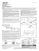
1. Remove the Corner/Head/Tail light from vehicle.
2. Select the location to mount the lighthead.
3. Carefully drill 1 inch diameter hole to the light assembly.
4. Insert lighthead into hole and secure with supplied sheet metal screws.
5. Apply silicone (user-supplied) for better seal.
To +VDC (fuse 4A@12V / 2A@24V)
To Chassis Ground
to lighthead
RED..........
BLACK.....
WHITE......
YELLOW...
Mounting screw holes
1 inch dia. hole
Supplied sheet
metal screw
Gasket
Lighthead
VEHICLE CORNER
LIGHT ASSEMBLY
Momentarily apply +VDC toYELLOW wire:
• once for next pattern
• quickly three times for FP#1
For Synchronization & Flash Patterns
Connect YELLOW wires of all Kits together for synchronization
*All kits must be set at the same pattern
For Simultaneous or Alternating Flash
*refer to “WIRING 2 KITS TOGETHER” on opposite page
LIGHT ASSEMBLY INSTALLATION
NOTE: This unit may not be
factory set at FP# 1.
*SPLIT = Head 1 alternate Head 2
*ALL = Head 1 & 2 Simultaneous
Flash Patterns
FP#
1Random
2Single (split)
3Double (split)
4Quad (split)
5Quint (split)
6Mega (split)
7Ultra (split)
8Single-Quad (split)
9Single H/L (split)
10 Single (all)
11 Double (all)
12 Quad (all)
13 Quint (all)
14 Mega (all)
15 Ultra (all)
16 Single-Quad (all)
17 Single H/L (all)
18 Steady Half
19 Steady All
WARNING: DO NOT cover heat sink with
silicone. It may cause damage to the
product and void warranty.
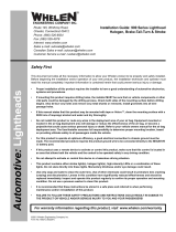
If the vehicle already has a strobe kit installed, the existing extension cables can be utilized to facilitate installation.
WIRING TO EXISTING STROBE CABLES
Disconnect strobe
extension cables from
strobe power supply.
STROBE
POWER SUPPLY
wol
l
eY
HAL09W FLASHER
to (+)
to GND
STROBE BULB
EXTENSION CABLE
(already in vehicle)
Connect LED Kit
connectors to strobe
extension cables.
Remove & Disconnect Strobe bulbs
from extension cables.
Insert & Connect LED Ligtheads to
strobe extension cables.
WARNING: Do not connect LED lightheads
directly strobe power supply. It will cause
damage and void the warranty.
NOTE: Wire colors of the LED Kit do not need
to match the wire colors of the extension cables.
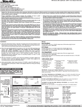
1. Use the mounting foam to mark wire and screws holes before drilling.
2. Carefully drill marked holes accordingly.
3. Insert the lighthead pigtail into wire hole.
4. Place the foam, the lighthead, and the bezel in line with the
mounting holes, and secure with supplied sheet metal screws.
FLANGE MOUNT INSTALLATION
NOTE: Make sure to use the foams
when mounting the lightheads.
Supplied sheet
metal screw Lighthead
Wire hole
0.91” (23mm)
VEHICLE
MOUNTING
SURFACE
to flasher
Mounting
Bezel
Foam
1.89” (48mm)
Mounting screw holes
NOTE: Carefully select the location to
mount the lighthead to achieve optimum
effect as vehicle reflectors may vary.
WARNING: Make sure the LED lightheads do not
interfere with the operation of vehicle lights.
HAL09W Flasher