Page is loading ...

Page 1
©2010 Whelen Engineering Company Inc.
Form No.14447A (050115)
51 Winthrop Road
Chester, Connecticut 06412-0684
Phone: (860) 526-9504
Fax: (860) 526-4078
Internet: www.whelen.com
Sales e-mail: [email protected]
Canadian Sales e-mail: [email protected]
Customer Service e-mail: [email protected]
Automotive: Sirens/Switches
Installation Guide:
Power Control Center
Model PCC6W
®
ENGINEERING COMPANY INC.
For warranty information regarding this product, visit www.whelen.com/warranty
Warnings to Installers
Whelen’s emergency vehicle warning devices must be properly mounted and wired in order to be effective and safe. Read and follow all of Whelen’s
written instructions when installing or using this device. Emergency vehicles are often operated under high speed stressful conditions which must be
accounted for when installing all emergency warning devices. Controls should be placed within convenient reach of the operator so that they can operate
the system without taking their eyes off the roadway. Emergency warning devices can require high electrical voltages and/or currents. Properly protect
and use caution around live electrical connections.Grounding or shorting of electrical connections can cause high current arcing, which can cause
personal injury and/or vehicle damage, including fire. Many electronic devices used in emergency vehicles can create or be affected by electromagnetic
interference. Therefore, after installation of any electronic device it is necessary to test all electronic equipment simultaneously to insure that they operate
free of interference from other components within the vehicle. Never power emergency warning equipment from the same circuit or share the same
grounding circuit with radio communication equipment. All devices should be mounted in accordance with the manufacturer’s instructions and securely
fastened to vehicle elements of sufficient strength to withstand the forces applied to the device. Driver and/or passenger air bags (SRS) will affect the way
equipment should be mounted. This device should be mounted by permanent installation and within the zones specified by the vehicle manufacturer, if
any. Any device mounted in the deployment area of an air bag will damage or reduce the effectiveness of the air bag and may damage or dislodge the
device. Installer must be sure that this device, its mounting hardware and electrical supply wiring does not interfere with the air bag or the SRS wiring or
sensors. Mounting the unit inside the vehicle by a method other than permanent installation is not recommended as unit may become dislodged during
swerving; sudden braking or collision. Failure to follow instructions can result in personal injury. Whelen assumes no liability for any loss resulting from the
use of this warning device. PROPER INSTALLATION COMBINED WITH OPERATOR TRAINING IN THE PROPER USE OF EMERGENCY WARNING
DEVICES IS ESSENTIAL TO INSURE THE SAFETY OF EMERGENCY PERSONNEL AND THE PUBLIC.
Warnings to Users
Whelen’s emergency vehicle warning devices are intended to alert other operators and pedestrians to the presence and operation of emergency vehicles
and personnel. However, the use of this or any other Whelen emergency warning device does not guarantee that you will have the right-of-way or that
other drivers and pedestrians will properly heed an emergency warning signal. Never assume you have the right-of-way. It is your responsibility to proceed
safely before entering an intersection, driving against traffic, responding at a high rate of speed, or walking on or around traffic lanes. Emergency vehicle
warning devices should be tested on a daily basis to ensure that they operate properly. When in actual use, the operator must ensure that both visual and
audible warnings are not blocked by vehicle components (i.e.: open trunks or compartment doors), people, vehicles, or other obstructions. It is the user’s
responsibility to understand and obey all laws regarding emergency warning devices. The user should be familiar with all applicable laws and regulations
prior to the use of any emergency vehicle warning device. Whelen’s audible warning devices are designed to project sound in a forward direction away
from the vehicle occupants. However, because sustained periodic exposure to loud sounds can cause hearing loss, all audible warning devices should be
installed and operated in accordance with the standards established by the National Fire Protection Association.
Safety First
This document provides all the necessary information to allow your Whelen product to be properly and safely installed. Before beginning the installation
and/or operation of your new product, the installation technician and operator must read this manual completely. Important information is contained herein
that could prevent serious injury or damage.
• Proper installation of this product requires the installer to have a good understanding of automotive electronics, systems and procedures.
• Whelen Engineering requires the use of waterproof butt splices and/or connectors if that connector could be exposed to moisture.
• Failure to use specified installation parts and/or hardware will void the product warranty.
• If mounting this product requires drilling holes, the installer MUST be sure that no vehicle components or other vital parts could be damaged
by the drilling process. Check both sides of the mounting surface before drilling begins. Also de-burr the holes and remove any metal shards
or remnants. Install grommets into all wire passage holes.
• If this manual states that this product may be mounted with suction cups, magnets, tape or Velcro®, clean the mounting surface with a 50/50
mix of isopropyl alcohol and water and dry thoroughly.
• Do not install this product or route any wires in the deployment area of your air bag. Equipment mounted or located in the air bag deployment
area will damage or reduce the effectiveness of the air bag, or become a projectile that could cause serious personal injury or death. Refer to
your vehicle owner’s manual for the air bag deployment area. The User/Installer assumes full responsibility to determine proper mounting
location, based on providing ultimate safety to all passengers inside the vehicle.
• For this product to operate at optimum efficiency, a good electrical connection to chassis ground must be made. The recommended
procedure requires the product ground wire to be connected directly to the NEGATIVE (-)
battery post (this does not include products that use cigar power cords).
• If this product uses a remote device for activation or control, make sure that this device is
located in an area that allows both the vehicle and the device to be operated safely in any
driving condition.
• It is recommended that these instructions be stored in a safe place and referred to when
performing maintenance and/or reinstallation of this product.
• FAILURE TO FOLLOW THESE SAFETY PRECAUTIONS AND INSTRUCTIONS COULD RESULT IN
DAMAGE TO THE PRODUCT OR VEHICLE AND/OR SERIOUS INJURY TO YOU AND YOUR
PASSENGERS!
CAUTION
Loud siren noise can cause
hearing damage and/or loss.
Refer to OSHA Section 1910.95 prior
to putting ANY siren into service!
Wear
Protection!
ACTIVATION OF THIS
SIREN MAY DAMAGE
UNPROTECTED EARS!
DANGER! Sirens produce extremely loud emergency warning tones! Exposure to these tones without proper and adequate hearing protection,
could cause ear damage and/or hearing loss! The Occupational Safety & Health Administration (www.osha.gov) provides information necessary to
determine safe exposure times in Occupational Noise Exposure Section 1910.95. Until you have determined the safe exposure times for your
specific application, operators and anyone else in the immediate vicinity should be required to wear an approved hearing protection device.
FAILURE TO FOLLOW THIS RECOMMENDATION COULD CAUSE HEARING LOSS!

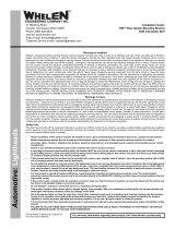
Page 2
Split Lock
Washer
Screw
Ext. Tooth
Lock Washer
SW1 SW10
►
Model PCC6W
WARNING! These switches are suitable for 25 amp, 12 volt DC
applications. Any attempt to load these switches above 25 amps will
result in switch failure.
WARNING! All customer supplied wires that connect to the positive
terminal of the battery must be sized to supply at least 125% of the
maximum operating current and be FUSED at the battery to carry
that load. DO NOT USE CIRCUIT BREAKERS WITH THIS PRODUCT!
Congratulations on selecting the PCC6W six switch power control center.
This product offers a unique and distinctive collection of features.
Features include:
• Ignition controlled LED backlighting
• Compact design
• Switch 'active' LED indicators
• Six 25 amp switches
• Two separate 'banks' of switches
• A common Ground Post
• 72 switch function labels
Mounting:
An aftermarket center console is recommended for the mounting location
of the PCC6W. This not only allows the driver to reach the controls easily,
but also keeps the unit safely out of the path of the vehicle’s SRS air-bag.
Follow the console manufacturer’s instructions for mounting information. If
a console-type mount is not possible, the PCC6W includes a bail strap
mounting kit for over or under dash mounting.
WARNING: Regardless of the style selected, be sure to observe the
air-bag warning on the cover of this manual.
WARNING: Mounting this unit will require drilling. It is absolutely
necessary to make sure that no other vehicle components could be
damaged in the process. Check both sides of the mounting surface
before starting. If damage is likely, select a different location.
Bail Strap Mount:
1. Position the bail strap in the
selected mounting location.
Using an awl or other suitable
tool, scribe the surface where
the mounting holes are to be
drilled.
2. Carefully drill the mounting
holes in the areas scribed in
step one. The size of the drill
bit should be determined by
the size of the mounting hardware (customer supplied) and the
thickness of the mounting surface.
3. Using the customer supplied mounting hardware, secure the bail
strap to the mounting location.
Console Mount:
Console manufacturers offer mounting kits that include all the necessary
hardware and brackets required to mount this unit into their console. The
console mount brackets are secured onto the unit the same way the bail
bracket is. Refer to the manual included with your console.
Function Labels: Take the supplied label kit and determine which label
describes the function of switch 1. Peel the label off the backing and place
it in the label window above switch 1. Press the label lightly into place.
Repeat for each switch.
Wiring:
BACKLT GND: This terminal supplies ground to both the units function
window backlighting and the switch 'active' LED indicators located on the
front of each switch. This terminal can be connected to any vehicle ground
that can supply 100ma.
BCKLT +V: This terminal supplies power to the units window backlighting.
This terminal can be connected to any ignition controlled +VBAT power
source that can supply 100ma.
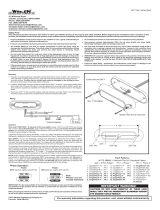
GND POST: The ground post has been included as a convenient place to
terminate the switched loads return path to ground (See wiring diagram).
To prepare the post, Remove the provided ring terminal and attach it to a
10 AWG wire, now run this wire from the ground post to the negative post
of the battery. All of the loads return ground wires can now use the ground
post for termination using a spade or a ring terminal (customer supplied).
+V IN: There are two terminals marked "+V IN". One terminal provides
power for switch bank 1 (switches 1, 2 & 3), while the other provides
power for switch bank 2 (switches 4, 5 & 6). Each switch can accommo-
date a maximum 25A current draw. However, the total combined current
draw of the three switches in either switch bank can not exceed 30 AMPS.
Each terminal will be wired directly to the Positive battery terminal using a
minimum 14AWG wire and fused @ 125% of the combined current draw
of all three switches in that bank (30A max).
Note: Remove the fuse from the fuse block before connecting any
wires to the battery. There must not be more than 2 ft. of wire between
the fuse block and the battery. Since the wire between the fuse and bat-
tery is “unprotected”, do not allow this wire to come in contact with other
wires.
OPTIONAL WIRING FOR +V IN: Since each bank of switches have their
own individual power source (labeled +V IN), if there is a requirement for
some of the vehicles equipment to be switched to ground rather than
+Vbat, it is possible to wire one of the banks power inputs (labeled +V IN)
to the negative post of the battery and use the associated switches in that
bank to enable the ground activated devices. (Note: if the bank is used for
ground activation, the Switch 'active' LED indicators will not light for any
switch in that bank)
SW1-SW6: Connect these terminals to the desired equipment (loads) as
shown in the wiring diagram, be sure to use the proper wire size to handle
the current required to power the equipment.
IMPORTANT: It is the responsibility of the installation technician to
make sure that the installation and operation of this product will not
interfere with or compromise the operation or efficiency of any vehi-
cle equipment! Before returning the vehicle to active service, visu-
ally confirm the proper operation of this product.
GND
POST
BCKLT GND
25A
Rear View
BANK 2
SWITCH OPTIONSSWITCH OPTIONS
BCKLT +V IN
+ V IN
SW 6 25A
SW 5 25A
SW 4 25A
SW 3 25A
+ V IN
SW 2 25A
SW 1 25A
25A
25A
25A
25A
25A
To +12 volt.
Ignition
activated
switch
BANK 1
PCC6W
WIRING
DIAGRAM
Fuse @
30 AMPS
Each (max)
LOAD
(+)
Battery
(-)
LOAD LOAD
LOAD LOAD LOAD
/