Page is loading ...

Programming guide
XTLC
ConTroL PaneL

Digital Monitoring Products XTLC Programming Guide
b
MODEL XTLC
CONTROL PANEL PROGRAMMING GUIDE
When using the XTLC control for any listing organization’s approved methods, refer to this manual and the XTLC
Installation Guide. These documents outline the installation and programming requirements of all applications for which
the XTLC is approved.
FCC Notice
This equipment generates and uses radio frequency energy and, if not installed and used properly in strict accordance with
the manufacturer’s instructions, may cause interference with radio and television reception. It has been type tested and
found to comply with the limits for a Class B computing device in accordance with the specication in Subpart J of Part 15
of FCC Rules, which are designed to provide reasonable protection against such interference in a residential installation.
If this equipment does cause interference to radio or television reception, which can be determined by turning the
equipment off and on, the installer is encouraged to try to correct the interference by one or more of the following
measures:
Reorient the receiving antenna
Relocate the computer with respect to the receiver
Move the computer away from the receiver
Plug the computer into a different outlet so that computer and receiver are on different branch circuits
If necessary, the installer should consult the dealer or an experienced radio/television technician for additional
suggestions. The installer may nd the following booklet, prepared by the Federal Communications Commission, helpful:
“How to identify and Resolve Radio-TV Interference Problems.”
This booklet is available from the U.S. Government Printing Ofce, Washington D.C. 20402
Stock No. 004-000-00345-4
© 2015 Digital Monitoring Products, Inc.
Information furnished by DMP is believed to be accurate and reliable.
This information is subject to change without notice.

XTLC Programming Guide Digital Monitoring Products
i
Table Of COnTenTs
Introduction .................................................................................................. 1
1.1 Before You Begin .......................................................................................................... 1
Programming Information Sheet .................................................................................... 1
1.2 Getting Started ............................................................................................................. 1
Initializing the Panel ...................................................................................................... 1
Program from an LCD or Wireless Keypad ....................................................................... 1
Wireless Keypad Association .......................................................................................... 1
Accessing the Programmer ............................................................................................ 1
1.3 Programming Menu ....................................................................................................... 2
1.4 Programmer Lockout Codes ........................................................................................... 2
Installing a lockout code ................................................................................................ 2
1.5 Reset Timeout .............................................................................................................. 2
1.6 Keypad ....................................................................................................................... 3
1.7 Special Keys ................................................................................................................. 3
COMMAND (CMD) Key ................................................................................................... 3
Back Arrow (<—) Key ..................................................................................................... 3
Select Keys ................................................................................................................... 3
1.8 Entering Alpha Characters ............................................................................................. 3
1.9 Entering Non-Alpha Characters ...................................................................................... 4
1.10 Keypad Displays Current Programming ........................................................................... 4
Initialization .................................................................................................. 5
2.1 Initialization.................................................................................................................. 5
2.2 Clear All Codes ............................................................................................................. 5
2.3 Clear All Schedules ........................................................................................................ 5
2.4 Clear Events ................................................................................................................. 5
2.5 Clear Zone Programming ............................................................................................... 5
2.6 Clear Communication .................................................................................................... 5
2.7 Set to Factory Defaults .................................................................................................. 5
Fast Program ................................................................................................. 6
3.1 Fast Program ................................................................................................................ 6
3.2 Account Number ........................................................................................................... 6
3.3 First IP Address ............................................................................................................ 6
3.4 System ......................................................................................................................... 6
3.5 Hours from GMT ........................................................................................................... 6
3.6 Weather Zip Code ......................................................................................................... 6
3.7 Serial Number............................................................................................................... 6
3.8 Zone Number ............................................................................................................... 6
3.9 Zone Name................................................................................................................... 6
3.10 Zone Type .................................................................................................................... 6
3.11 Area Assignment ........................................................................................................... 6
3.12 Serial Number Entry ...................................................................................................... 6
3.14 Stop ............................................................................................................................. 6
Communication ............................................................................................. 7
4.1 Communication ............................................................................................................. 7
4.2 Account Number ........................................................................................................... 7
4.3 Transmission Delay ....................................................................................................... 7
4.4 Communication Type ..................................................................................................... 7
4.5 Test Time ..................................................................................................................... 7
4.6 Test Days ..................................................................................................................... 7
4.7 Cell Check In ................................................................................................................ 7
4.8 Fail Time ...................................................................................................................... 7
4.9 First GPRS APN ............................................................................................................. 7
4.10 Second GPRS APN ......................................................................................................... 8
4.11 Receiver 1 Programming................................................................................................ 8
4.12 Alarm Reports ............................................................................................................... 8

Digital Monitoring Products XTLC Programming Guide
ii
Table of ConTenTs
4.13 Supervisory/Trouble Reports .......................................................................................... 8
4.14 Opening/Closing and User Reports ................................................................................. 8
4.15 Test Report ................................................................................................................... 8
4.16 First IP Address ............................................................................................................ 8
4.17 First IP Port .................................................................................................................. 8
4.18 Second IP Address ........................................................................................................ 8
4.19 Second IP Port .............................................................................................................. 8
4.20 Receiver 2 Programming................................................................................................ 8
4.21 Alarm Reports ............................................................................................................... 8
4.22 Supervisory/Trouble Reports .......................................................................................... 8
3.23 Opening/Closing and User Reports ................................................................................. 8
4.24 Test Report ................................................................................................................... 9
4.25 First IP Address ............................................................................................................ 9
4.26 First IP Port .................................................................................................................. 9
4.27 Second IP Address ........................................................................................................ 9
4.28 Second IP Port .............................................................................................................. 9
Messaging Setup ......................................................................................... 10
5.1 Messaging Setup ......................................................................................................... 10
5.2 Enable Messaging ....................................................................................................... 10
5.3 System Name ............................................................................................................. 10
5.4 Destination 1 .............................................................................................................. 10
5.5 Destination 1 User Number .......................................................................................... 10
5.6 Destination 2 .............................................................................................................. 10
5.7 Destination 2 User Number .......................................................................................... 10
5.8 Destination 3 .............................................................................................................. 10
5.9 Destination 3 User Number .......................................................................................... 10
5.10 O/C Email ................................................................................................................... 11
5.11 O/C SMS .................................................................................................................... 11
5.12 Monthly Limit .............................................................................................................. 11
Device Setup ............................................................................................... 12
6.1 Device Setup .............................................................................................................. 12
6.2 Device Number ........................................................................................................... 12
6.3 Device Name .............................................................................................................. 12
6.4 Wireless ..................................................................................................................... 12
6.5 Serial Number............................................................................................................. 12
6.6 Supervision Time ........................................................................................................ 12
Remote Options .......................................................................................... 13
7.1 Remote Options .......................................................................................................... 13
7.2 Remote Key ................................................................................................................ 13
7.3 Remote Disarm ........................................................................................................... 13
System Reports ........................................................................................... 14
8.1 System Reports .......................................................................................................... 14
8.2 Opening/Closing Reports ............................................................................................. 14
8.3 Abort Reports ............................................................................................................. 14
8.4 Zone Restoral Reports ................................................................................................. 14
8.5 Bypass Reports ........................................................................................................... 14
8.6 Code Change Reports .................................................................................................. 14
8.7 Ambush ..................................................................................................................... 14
8.8 Late To Open .............................................................................................................. 14
8.9 Early To Close ............................................................................................................. 14
System Options ........................................................................................... 15
9.1 System Options .......................................................................................................... 15
9.2 System ....................................................................................................................... 15
9.3 Closing Code .............................................................................................................. 15

XTLC Programming Guide Digital Monitoring Products
iii
Table Of COnTenTs
9.4 Closing Check ............................................................................................................. 15
9.5 Entry Delay 1 .............................................................................................................. 15
9.6 Exit Delay ................................................................................................................... 15
9.7 Cross Zone Time ......................................................................................................... 16
9.8 Power Fail Delay ......................................................................................................... 16
9.9 Swinger Bypass Trips .................................................................................................. 16
9.10 Reset Swinger Bypass ................................................................................................. 16
9.11 Zone Activity Hours ..................................................................................................... 16
9.12 Arm Activity Days ........................................................................................................ 16
9.13 Time Zone Changes .................................................................................................... 17
9.14 Time Display............................................................................................................... 17
9.15 House Code ................................................................................................................ 17
9.15.1 Detect Wireless Jamming ............................................................................................ 17
9.15.2 Wireless Audible Annunciation ..................................................................................... 17
9.16 Enable Keypad Panic Keys ........................................................................................... 17
9.17 Occupied Premises ...................................................................................................... 18
9.18 Use False Alarm Question ............................................................................................ 18
9.19 Weather Zip Code ....................................................................................................... 18
Bell Options ................................................................................................. 19
10.1 Bell Options ................................................................................................................ 19
10.2 Bell Cutoff Time .......................................................................................................... 19
10.3 Automatic Bell Test ..................................................................................................... 19
10.4 Bell Output ................................................................................................................. 19
10.5 Bell Action .................................................................................................................. 19
10.5.1 Fire ............................................................................................................................ 19
10.5.2 Burglary ..................................................................................................................... 19
10.5.3 Supervisory ................................................................................................................ 19
10.5.4 Panic .......................................................................................................................... 19
10.5.5 Emergency ................................................................................................................. 19
10.5.6 Auxiliary 1 .................................................................................................................. 19
10.5.7 Auxiliary 2 .................................................................................................................. 19
Output Options ............................................................................................ 20
11.1 Output Options ........................................................................................................... 20
11.2 Communication Failure Output ..................................................................................... 20
11.3 Fire Alarm Output ....................................................................................................... 20
11.4 Panic Alarm Output ..................................................................................................... 20
11.5 Entry Output .............................................................................................................. 20
11.6 Begin Exit Output ........................................................................................................ 20
11.7 End Exit Output .......................................................................................................... 20
11.8 Armed Output ............................................................................................................. 20
11.9 Disarmed Output ........................................................................................................ 21
11.10 Burglary Output .......................................................................................................... 21
11.11 Ready Output ............................................................................................................. 21
11.12 Arm-Alarm Output ....................................................................................................... 21
11.13 Heat Saver Temperature .............................................................................................. 21
11.14 Cool Saver Temperature .............................................................................................. 21
Output Setup ............................................................................................... 22
12.1 Output Setup .............................................................................................................. 22
12.2 Output Number .......................................................................................................... 22
12.3 Output Name .............................................................................................................. 22
12.4 Serial Number............................................................................................................. 22
12.5 Supervision Time ........................................................................................................ 22
12.6 Trip with Panel Bell Option ........................................................................................... 22

Digital Monitoring Products XTLC Programming Guide
iv
Table of ConTenTs
Area Information ......................................................................................... 23
13.1 Area Information ........................................................................................................ 23
13.2 Area Number .............................................................................................................. 23
13.3 Area Name ................................................................................................................. 23
13.4 Automatic Arming ....................................................................................................... 23
13.4.1 Bad Zones .................................................................................................................. 23
13.5 Automatic Disarming .................................................................................................. 23
Zone Information ........................................................................................ 24
14.1 Zone Information ........................................................................................................ 24
14.2 Zone Number ............................................................................................................. 24
14.3 Key Fob ...................................................................................................................... 24
14.4 Zone Name................................................................................................................. 25
14.5 Zone Type .................................................................................................................. 25
14.6 Area Assignment ......................................................................................................... 25
14.7 Arming Zone Assignment ............................................................................................. 25
14.7.1 Style .......................................................................................................................... 26
DMP Wireless ............................................................................................................. 26
14.9 Serial Number Entry .................................................................................................... 26
14.10 Contact ...................................................................................................................... 26
14.10.1 Supervision Time ........................................................................................................ 27
14.10.2 LED Operation ............................................................................................................ 27
14.10.3 Disarm/Disable ........................................................................................................... 27
14.10.4 Wireless PIR Pulse Count ............................................................................................. 27
14.10.5 Wireless PIR Sensitivity ............................................................................................... 27
14.10.6 Next Zone .................................................................................................................. 27
14.11 Series Key Fobs .......................................................................................................... 28
14.11.1
Key Fob User Number ................................................................................................. 28
14.11.2 Key Fob Serial Number ................................................................................................ 28
14.11.3
Key Fob Supervision Time ............................................................................................ 28
14.11.4
Number of Key Fob Buttons ......................................................................................... 28
14.11
.5 Key Fob Button Selection (Four Buttons) ....................................................................... 28
14.11
.6 Key Fob Button Selection (Two Buttons) ....................................................................... 28
14.11
.7 Button Action ............................................................................................................. 28
14.11
.8 Button Press Time ....................................................................................................... 29
14.11
.9 Arm/Disarm Area Selection .......................................................................................... 29
14.11
.10
Output Number .......................................................................................................... 29
14.11
.11
Output Action ............................................................................................................. 29
14.12 Alarm Action ............................................................................................................... 30
14.13 Disarmed Open ........................................................................................................... 30
14.13.1 Message To Transmit ................................................................................................... 30
14.13.2 Output Number .......................................................................................................... 30
14.13.3 Output Action ............................................................................................................. 31
14.14 Swinger Bypass .......................................................................................................... 31
14.15 Prewarn Address ......................................................................................................... 31
14.16 Entry Delay ................................................................................................................ 31
14.17 Cross Zone ................................................................................................................. 31
14.18 Priority ....................................................................................................................... 32
14.19 TrafcCount ............................................................................................................... 32
14.20 Zone Audit Days ......................................................................................................... 32
14.21 Receiver Routing ......................................................................................................... 32
14.22 Zone Number ............................................................................................................. 32
Stop ............................................................................................................. 33
15.1 Stop ........................................................................................................................... 33

XTLC Programming Guide Digital Monitoring Products
v
Table Of COnTenTs
Set Lockout Code ........................................................................................ 33
16.1 Set Lockout Code ........................................................................................................ 33
Appendix ..................................................................................................... 34
17.1 Status List .................................................................................................................. 34
17.2 Transmission Delay ..................................................................................................... 34
17.3 False Alarm Reduction ................................................................................................. 34
System Recently Armed report ..................................................................................... 34
17.4 Diagnostics Function ................................................................................................... 34
Cellular Status ............................................................................................................ 34
Cellular Signal Strength (CELL SIGNAL) ........................................................................ 34
Cell Roaming Indicator on XTLC ................................................................................... 35
Cellular Activation ....................................................................................................... 35
Panel Settings ............................................................................................................. 35
Serial Number............................................................................................................. 35
Panel Model ................................................................................................................ 35
Firmware Version ........................................................................................................ 35
Z-Wave Test Option ..................................................................................................... 35
Exiting the Diagnostics program ................................................................................... 35
17.5 Using the 984 Command Function ................................................................................ 36
17.6 Using the Walk Test .................................................................................................... 36
Walk Test ................................................................................................................... 36
Trip Counter For DMP Wireless Check-in Test (WLS) ...................................................... 36
Test End Warning ........................................................................................................ 36
Failed Zones Display .................................................................................................... 36
17.7 Keypad Speaker Operation........................................................................................... 37
17.8 Cross Zoning .............................................................................................................. 37
17.9 Zone Type Descriptions ............................................................................................... 37
17.9 Zone Type Defaults ..................................................................................................... 38
17.10 Common Keypad Messages ......................................................................................... 39
17.11 Z-WaveCerticationInformation .................................................................................. 39
Revisions to This Document ........................................................................ 40
Certications ............................................................................................................................. 42

XTLC Programming Guide Digital Monitoring Products
1
IntroductIon
Introduction
1.1 Before You Begin
Before starting to program, we recommend you read through the contents of this manual. The information in
this document allows you to quickly learn the programming options and operational capabilities of the XTLC
panel.
After this Introduction, the remaining sections describe the functions of each programming menu items along
with their available options. The XTLC contains all of its programming information in an on-board processor and
does not require an external programmer.
In addition to this manual, you should also be familiar with the following documents:
• XTLC Installation Guide (LT-1105)
• XTLC/XTLN/XTLN-WiFi User’s Guide (LT-1109)
• XTLC Programming Sheet (LT-1095)
• XTLC Fast Programming Sheet (LT-1095F)
Programming Information Sheet
Included with each XTLC panel is the Programming Sheet and Fast Programming Sheet. These sheets lists the
various options available for programming the panel. Before starting, completely ll out the sheet with the
programming options you intend to enter into the panel.
Having completed programming sheets available while entering data helps to prevent errors and can shorten
the length of time you spend programming. Completed sheets also provide you with an accurate account of the
panel’s program you can keep on le for future system service or expansion.
The remainder of the Introduction explains starting and ending a programming session.
1.2 Getting Started
Ground Yourself Before Handling the Panel! Touch any grounded metal before touching the panel to discharge
static.
The XTLC panel should be completely installed before you begin programming. Make sure the AC and battery
wires are correctly installed.
Initializing the Panel
When programming a panel for the rst time or rewriting the entire program of an existing XTLC, use the
Initialization function described in section 2. Initializing clears the panel’s memory of any old data and sets the
highest numbered user number to user code 99.
Program from an LCD or Wireless Keypad
You can program the panel using an LCD Keypad connected to the panel PROG header.
Wireless Keypads can be used for panel programming after being programmed in the panel manually or by using
the Wireless Keypad Association operation.
Wireless Keypad Association
To enable association operation in the XTLC panel, reset the panel three times as described below and observe
the operation of Green LED and Red Backlit Logo LED’s. When in keypad association, the XTLC Red and Green
backlit logo LEDs turn on steady.
1. Press RESET.
2. The Green LED turns off.
3. The Green LED and Red LED turns on steady then off.
4. The Green LED turns on again.
Repeat steps 1 - 4 two more times or until both the Green LED and Red LED remain on steady.
For 60 seconds the panel listens for wireless keypads that are in the Installer Options Menu (3577 CMD) and
have not been programmed, or associated into another panel. Those keypads are assigned to the rst open
device position automatically based upon the order in which they are detected. The keypad logo turns Green to
indicate it has been associated with the panel. See the 9000 Series Wireless Keypad Installation Guide (LT-1107)
for additional information.
Note: Programming can not be accessed using an Icon Series keypad. Use a 32-character keypad to complete
the panel programming.
Accessing the Programmer
To access the programmer function of the XTLC:
1. If using a standard LCD keypad, connect to the PROG header and set the keypad to Address 1.
2. If using a wireless LCD keypad, make sure panel communication has been established and the user menu
appears on an associated keypad before continuing.
3. Press the RESET button for two seconds.
4. Enter the code 6653 (PROG).
5. The keypad displays: PROGRAMMER.
6. Remove the hardwired keypad (if used) when programming is completed.

Digital Monitoring Products XTLC Programming Guide
2
IntroductIon
1.3 Programming Menu
You are now ready to start programming the XTLC panel. Pressing the COMMAND key scrolls you through the
programming menu items listed below.
Menu Item Section in This Manual Menu Item Section in This Manual
Initialization 2 Bell Options 10
Fast Program 3 Output Options 11
Communication 4 Output Setup 12
Messaging Setup 5 Area Information 13
Device Setup 6 Zone Information 14
Remote Options 7 Stop 15
System Reports 8 Set Lockout Code 16
System Options 9 Appendix 17
To select a section for programming, press any Select key when the name of that section displays on the
keypad. The detailed instructions for each programming step are found in sections 2 to 17 of this manual.
1.4 Programmer Lockout Codes
Although the XTLC panel allows access to Programming without a lockout code, it is available to program one to
restrict programming access to authorized individuals only. You can do this by using SET LOCKOUT CODE at the
end of the programming menu.
Installing a lockout code
1. After entering the Programmer menu, the keypad displays PROGRAMMER. Press the COMMAND key until
SET LOCKOUT CODE is displayed (after STOP).
2. Press any Select key. At the ENTER CODE: - display, enter a 1- to 5-digit programmer lockout code. Press
COMMAND.
3. The display shows ENTER AGAIN. Enter the same lockout code again and press COMMAND. The display
shows CODE CHANGED. The new code number must now be entered before the Programmer menu can
be accessed.
The lockout code should be written down and kept in a secure place with access limited to authorized persons
only.
Lost Lockout Code requires factory reset: If you lose or forget the lockout code, the panel must be sent back
to the factory to be reset. There is no eld option for gaining access to the panel without a valid lockout code.
1.5 Reset Timeout
The XTLC has a feature that requires you to enter the Programmer within 30 minutes of resetting the panel.
After 30 minutes, if you attempt to program by entering the 6653 (PROG) code, the keypad displays: RESET
PANEL. You must reset the panel and enter the program code within the next 30 minutes.
If you are already in the Programmer and do not press any keys on the programming keypad for 30 minutes, the
panel terminates programming. All data entered up to that point is saved in the panel’s memory.
To exit the panel’s Programmer you must use the Stop function. The STOP option is the second to the last
option in programming. The programming session is then terminated and the keypad returns to the Status List.

XTLC Programming Guide Digital Monitoring Products
3
IntroductIon
1.6 Keypad
Connect up to four DMP 9060 and 9063 Wireless LCD Keypads to the XTLC panel. The operation is shown and
described in the following sections.
1.7 Special Keys
The following special keys are common to all DMP keypads.
COMMAND (CMD) Key
Pressing the COMMAND key allows you to go forward through the programming menu and through each step of a
programming sec tion. As you go through the programming, the keypad display shows any current programming
already stored in the panel memory. If no change is required for an option, press the COMMAND key to advance
to the next step.
The COMMAND key is also used to enter information into the panel’s memory such as phone numbers or zone
names. Press the COMMAND key after entering information.
Back Arrow (<—) Key
Use the Back Arrow key to back up one step while programming. The Back Arrow key is also used when an error
is made while entering in formation. Press the Back Arrow key once to erase the last character entered.
Select Keys
The top row of keys are called the Select keys on the 9000 Series Wireless Keypad.
Each time you need to press a Select key on 9000 Series keypad, the keypad displays the function or options
above one of the keys. Displaying choices above individual Select keys allows them to be used for many
different applications. For example, you can enter AM or PM when programming the automatic test time or
answer YES or NO for a system option.
During programming, the Select keys also allow you to change infor mation currently in panel memory by
pressing the appropriate Select key under or on the display. You then enter the new information using the
keypad data entry digit keys. The Select keys are also used for choosing a section from the pro gramming menu.
When the programming section name you want displays, press any Select key.
When there are more than four re sponse options avail able, press the COMMAND key to display the next one to
four options. Pressing the Back Arrow key allows you to review the previous four choices.
Note: When instructed to press the rst Select key, press the far left Select key; the second Select key is the
second from the left; third Select key is second from the right; and the fourth Select key is the far right key.
See Figure 2.
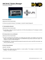
1.8 Entering Alpha Characters
Some options during programming require you to enter alpha characters. To enter an alpha character, press
or touch the key that has that letter written below it. The keypad displays the number digit of the key. Next,
press the Select key that corresponds to the loca tion of the letter under the key. Pressing a different Select key
changes the letter. When an other digit key is pressed, the last
letter displayed is retained and the process starts over.
32-Character Display
Data Entry Digit keys
COMMAND Key
Back Arrow Key
Select Keys
1 2 3 4
9 0 CMD
5 6 7 8
SMITH HOME
FRI 2:51 AM
Backlit Logo
and Proximity
Antenna
Figure 1: 9000 Series Wireless Keypad
First Letter
Second Letter
Third Letter
Special Character
(CBA
Figure 2: 9060/9063 Select Keys

Digital Monitoring Products XTLC Programming Guide
4
IntroductIon
1.9 Entering Non-Alpha Characters
To enter a space in an alpha entry, press the 9 digit key followed by the third Select key. The three characters
on the 9 digit key are Y, Z, and space. You can also enter the following characters: – (dash), . (period), *
(asterisk), and # (pound sign) using the 0 (zero) key and the four Select keys from left to right. For example, to
enter a – (dash), press the 0 (zero) key and then the left Select key. A dash now appears in the keypad display.
The table below shows the character locations for DMP keypads.
Key Number Select Key 1 Select Key 2 Select Key 3 Select Key 4
1 A B C (
2 D E F )
3 G H I !
4 J K L ?
5 M N O /
6 P QR &
7 S T U @
8 V W X ,
9 Y Z space _
0 - . * #
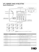
1.10 Keypad Displays Current Programming
Each programming option displayed at the keypad shows the currently selected option in the panel memory.
These options are either shown as a number, a blank, or a NO or YES. To change a number or blank to a new
number, press any top row Select key. The current option is replaced with a dash. Press the number(s) on the
keypad you want to enter as the new number for that option. It is not necessary to enter numbers with leading
zeros. The panel automatically right justies the number when you press the COMMAND key.
To change a programming option that requires a NO or YES response, press the Select key for the response not
selected. See Figure 3.
For example, if the current option is selected as YES and you want to change it to NO, press the third top row
Select key. The display changes to NO. Press the COMMAND key to display the next option.
THEN
Press the third top row
Select key.
The keypad displays the new
selection. Press CMD to advance.
YESBELL TST NOBELL TST
Figure 3: Changing the Current Programming Option

XTLC Programming Guide Digital Monitoring Products
5
InItIalIzatIon
Initialization
2.1 Initialization
This function allows you to set the panel’s programmed memory back to the factory
defaults in preparation for system programming.
After you select YES to clear a section of memory, the panel asks if you are sure you
want to clear the memory. This is a safeguard against accidently erasing part of your
programming. No memory is cleared from the programming until you answer YES to the
SURE? YES NO option.
CODES? NO YES
SCHEDS? NO YES
For each section of the panel program you
can initialize, a NO or YES option is provided.
Selecting YES advances you to
a confirmation prompt.
If you select YES, the panel initializes that section of
the program and advances you to the next prompt.
If you select NO, the panel advances you to the next
section prompt but does not initialize that section of
the program.
SURE?YESNO
Selecting NO advances
you to the next prompt.
2.2 Clear All Codes
NO leaves existing user codes intact.
YES clears the user code memory and assigns the user code number 99 to user 30 on the
XTLC.
2.3 Clear All Schedules
NO - Leaves existing schedules intact.
YES - Clears all schedules from panel programming.
2.4 Clear Events
NO leaves existing event memory intact.
YES clears all event memory currently held in the panel’s Display Events buffer.
2.5 Clear Zone Programming
NO leaves existing zone information intact.
YES sets all zones in the system to * UNUSED *
2.6 Clear Communication
NO - Leaves existing communication and messaging programming intact.
YES - Clears communication and messaging programming to factory defaults.
2.7 Set to Factory Defaults
NO leaves the remainder of the existing panel programming intact.
YES sets the panel’s programming back to factory default selections and clears all
Z-Wave device programming and all Favorites from the panel. Selecting YES does not
clear the panel’s event memory, zone, user code information, or schedules.
INITIALIZATION
CODES? NO YES
SURE? YES NO
SCHEDS? NO YES
SURE? YES NO
EVENTS? NO YES
SURE? YES NO
ZONES? NO YES
SURE? YES NO
COMM? NO YES
SURE? YES NO
DEFAULTS? NO YES
SURE? YES NO

Digital Monitoring Products XTLC Programming Guide
6
Fast Program
Fast Program
3.1 Fast Program
The Fast Program section allows you to quickly congure the essential settings for
the XTLC panel. When the panel programming defaults are acceptable for installation
and only basic programming options are needed, FAST PROGRAM allows the installer
to quickly enter information without navigating all of the programming menus. After
choosing FAST PROGRAM, continue through the basic list of options.
3.2 Account Number
Enter the account num ber sent to the receiver. See Communication.
3.3 First IP Address
Enter the rst (primary) IP address where the panel sends cell messages. See
Communication.
3.4 System
This congures the panel as either a six Area system, an All/Perimeter system
(Perimeter/Interior), or a Home/Away system (Perimeter, Interior, and Bedrooms). See
System Options.
3.5 Hours from GMT
Enter the number (0-23) that indicates the Greenwich Time zone (GMT) where the panel
is located. See System Options.
3.6 Weather Zip Code
Enter the zip code of the user at this option. See System Options.
3.7 Serial Number
Enter the eight-digit serial number for the wireless siren. The siren is automatically set
to Output 41. See Output Setup.
3.8 Zone Number
Enter the zone number to program. See Zone Information.
3.9 Zone Name
Press any Select key to display the default zone name. To change the default zone name,
press any Select key to clear name. Enter up to 16 characters for the new zone name.
3.10 Zone Type
To change the default zone type press any select key. See Zone Information.
3.11 Area Assignment
To change the default area, press any Select key.
3.12 Serial Number Entry
Enter the eight digit serial number, including leading zeros, found on the wireless
device.
3.14 Stop
When all zones are programmed, press the Back Arrow key to display FAST PROGRAM.
Press COMMAND to display STOP and press any Select key to exit the Fast Program
function and save the programming. See Stop.
Note: All programming options are still available by reentering the programming menu.
FAST PROGRAM
ACCOUNT NO:
FIRST IP ADDR
000.000.000.000
SYSTEM: ALL/PERIM
AREA A/P H/A
HRS FROM GMT: 6
ENTER WEATHER
ZIP CODE: 0
ENTER SIREN
SERIAL#:-
ZONE NO: -
* DEFAULT NAME *
ZONE TYPE: -
AREA: -
SERIAL #: -
STOP

XTLC Programming Guide Digital Monitoring Products
7
CommuniCation
Communication
4.1 Communication
The Communication section allows you to congure the communication settings for
the XTLC panel. After choosing the Communication Type, continue through the list of
options.
4.2 Account Number
Enter the account num ber sent to the receiver.
The range of account numbers are 1 to 65535. For account numbers of four digits or
less, you do not have to enter leading zeros. The panel automatically right justies the
account number.
4.3 Transmission Delay
Enter the number of seconds (15 to 45 seconds) the panel waits before sending burglary
alarm reports to the receiver. The wireless siren and relay outputs are not delayed during
this period. Enter 0 (zero) to disable this function. The default is 30.
4.4 Communication Type
This species the communication method the panel uses to contact the receiver. Press
any Select key to display the following communication options:
CELL - Cellular communication to DMP Model SCS-1R or SCS-VR Receivers.
NONE - For local systems. Selecting this ends communication programming.
Note: XTLC cellular communication must be activated using the Activate Cell option
provided in section 17.4 Diagnostics Function located in the Appendix.
4.5 Test Time
Press COMMAND to enter the Test Time. Enter the time of day the panel sends the test
report to the SCS-1R Receiver. Use entries between 12:00 to 11:59 and then choose AM
or PM.
4.6 Test Days
Enter how often the panel test report is sent to the receiver. Enter from 1 to 60 days.
Enter zero to disable the test report
. Default is 1 (one) day. This option only displays if a
test time is entered.
4.7 Cell Check In
Check-in reports are a method of supervising the panel for communication with the
receiver.
Enter the number of minutes between check-in reports. Select from 0 or 3-240 minutes.
Enter 0 (zero) to disable the check-in option. Default is 0.
Note: If Cell Check-in option is used, additional cell charges may apply.
4.8 Fail Time
Fail Time allows the SCS-1R or SCS-VR receiver to miss a dened number of check-ins
before logging that the panel is missing. For example, if CELL CHECKIN is 20 and FAIL
TIME is 30, the SCS-1R receiver only indicates a Panel Not Responding after 30 minutes.
The FAIL TIME must be equal to or greater than the CELL CHECKIN minutes: If the
CHECKIN is 20 minutes, the FAIL TIME must be 20 or more. The maximum FAIL TIME is
240 minutes. Select from 0 or 3-240 minutes. The default FAIL TIME is 240 minutes.
Closing Wait operation: Closing Wait operation is activated if Fail Time is set
to 3 minutes and O/C Reports in System Reports is YES and O/C User reports in
Communication Programming is set to YES.
Closing Wait provides a delay time before a monitored system arms until the panel
receives an acknowledgment of the closing report from the central station receiver.
During the delay, the keypad displays ONE MOMENT . . . Once the closing is
acknowledged from the SCS-1R receiver, the keypad buzzes for one second and then
displays an armed status message. If the primary communication fails, the message
LOCAL ALARM ONLY appears.
4.9 First GPRS APN
Enter the rst APN (Access Point Name). This allows an access point for cellular
communication and is used to connect to a DNS network. The APN may contain two lines
of 16 characters to equal 32 characters. Default is set to SECURECOM400.
COMMUNICATION
ACCOUNT NO:
XMIT DELAY: 30
COMM TYPE: CELL
CELL NONE
TEST TIME
00:00 AM PM
CELL TST DAYS: 1
CELL CHECKIN: 0
FAIL TIME: 240
SECURECOM400
-
FIRST GPRS APN

Digital Monitoring Products XTLC Programming Guide
8
CommuniCation
4.10 Second GPRS APN
Enter the second APN (Access Point Name). This works as a backup in case the rst APN
fails. The APN may contain two lines of 16 characters to equal 32 character Default is set
to SECURECOM400.
4.11 Receiver 1 Programming
Allows you to set the options for the rst receiver the panel attempts to contact when
sending reports. The XTLC supports communication to two receivers.
4.12 Alarm Reports
YES enables Abort, Alarm, Alarm Restoral, Alarm Bell Silenced, Ambush, Exit Error, and
System Recently Armed reports to be sent to this receiver. Default is YES.
4.13 Supervisory/Trouble Reports
YES enables Supervisory, Trouble, Trouble Restoral, Force Armed, Late to Close, and
Fault reports to be sent to this receiver. Default is YES.
4.14 Opening/Closing and User Reports
YES enables Opening/Closing, Code Changes, and Bypass reports by user to be sent to
this receiver. Default is NO.
4.15 Test Report
Enter YES to enable the Recall Test report to be sent to this receiver.
4.16 First IP Address
Enter the rst (primary) IP address where the panel sends cell messages. Enter all
12 digits and leave out the periods. For example, enter IP address 192.168.0.250 as
192168000250. The periods display automatically.
The message is sent using rst GPRS APN and the rst IP Address. If no acknowledgment
is received, rst GPRS APN and the second IP address are used, followed, if needed, by
second GPRS APN and rst and second IP addresses, respectively.
4.17 First IP Port
Enter the rst IP port number to be used in conjunction with the rst IP Address. The
IP port identies the port used to communicate messages to and from the panel. The
default IP Port setting is 2001.
4.18 Second IP Address
Enter the second IP address where the panel sends network messages. Enter all 12
digits and leave out the periods. For example, enter IP address 192.168.0.250 as
192168000250. The periods display automatically.
4.19 Second IP Port
Enter the second IP port number to be used in conjunction with the second IP address.
The IP port identies the port used to communicate messages to and from the panel.
The default IP Port setting is 2001.
4.20 Receiver 2 Programming
Allows you to set the options for the second receiver the panel attempts to contact
when sending reports. The XTLC supports communication to two receivers. If you select
YES for any of the Receiver 2 options, you must have at least one IP address programmed
in Receiver 2 programming. Receiver 2 defaults are set to NO.
4.21 Alarm Reports
YES enables Abort, Alarm, Alarm Restoral, Alarm Bell Silenced, Ambush, Exit Error, and
System Recently Armed reports to be sent to this receiver. Default is NO.
4.22 Supervisory/Trouble Reports
YES enables Supervisory, Trouble, Trouble Restoral, Force Armed, Late to Close, and
Fault reports to be sent to this receiver. Default is NO.
3.23 Opening/Closing and User Reports
YES enables Opening/Closing, Code Changes, and Bypass reports by user to be sent to
this receiver. Default is NO.
SECURECOM400
-
SECOND GPRS APN
RECEIVER 1 PROG
ALARM NO YES
SPV/TRBL NO YES
O/C USER NO YES
TEST RPT NO YES
FIRST IP ADDR
000.000.000.000
FIRST IP PORT
2001
SECOND IP ADDR
000.000.000.000
SECOND IP PORT
2001
RECEIVER 2 PROG
ALARM NO YES
SPV/TRBL NO YES
O/C USER NO YES

XTLC Programming Guide Digital Monitoring Products
9
CommuniCation
4.24 Test Report
YES enables the Recall Test report to be sent to this receiver. Default is NO.
4.25 First IP Address
Enter the rst (primary) IP address where the panel sends cell messages. Enter all
12 digits and leave out the periods. For example, enter IP address 192.168.0.250 as
192168000250. The periods display automatically.
The message is sent using rst GPRS APN and the rst IP Address. If no acknowledgment
is received, rst GPRS APN and the second IP address are used, followed, if needed, by
second GPRS APN and rst and second IP addresses, respectively.
4.26 First IP Port
Enter the rst IP port number to be used in conjunction with the First IP Address. The
IP port identies the port used to communicate messages to and from the panel. The
default IP Port setting is 2001.
4.27 Second IP Address
Enter the second IP address where the panel sends cell messages. Enter all 12 digits and
leave out the periods. For example, enter IP address 192.168.0.250 as 192168000250.
The periods display automatically.
4.28 Second IP Port
Enter the second IP port number to be used in conjunction with the second IP Address.
The IP port identies the port used to communicate messages to and from the panel.
The default IP Port setting is 2001.
TEST RPT NO YES
FIRST IP ADDR
000.000.000.000
FIRST IP PORT
2001
SECOND IP ADDR
000.000.000.000
SECOND IP PORT
2001

Digital Monitoring Products XTLC Programming Guide
10
Messaging setup
Messaging Setup
5.1 Messaging Setup
This section allows you to enter the information needed to send and receive messages
directly to and from the panel via email and MyAccess™ text messaging using CDMA
cellular communication. All of the name and password options below allow up to 32
lowercase characters to be entered. The Destination addresses allow up to 48 characters
to be entered. System Name is displayed with initial caps.
The transmitted messages are:
• Zone Alarms by Zone Name
• Zone Troubles by Zone Name
• Zone Bypass by User
• Arming (Closings) by User
• Disarming (Openings) by User
• Late to Close
• Late to Open
• Early to Close
• AC Power Trouble and Restoral
• System Low Battery
• Ambush
• Abort, Cancel and Alarm Veried by User
• Check-in by User
5.2 Enable Messaging
Select YES to allow the panel to send messages to three programmed destinations.
Default is NO.
5.3 System Name
Enter a unique name for the panel. The panel name is used as the sender of the
message. The text entered is displayed with initial caps. If this eld is left blank, the
panel account number
is sent.
5.4 Destination 1
Enter the rst email address or cell phone number where messages will be sent. The
message can be sent to any device (computer, cell phone, PDA) as long as a valid email
address or cell phone number is entered. When entering email addresses, press the
7 digit key followed by the fourth Select Key to add the @ symbol and the 9 digit key
followed by the fourth Select Key to add the _ symbol. See the Entering Non-Alpha
Characters section for additional symbols.
Note: Mail servers that require Transport Layer Security (TLS) encryption are not
supported by the XTLC.
5.5 Destination 1 User Number
If Destination 1 is a 10-digit cellular number, enter a user’s user number from this account.
This option is used when sending commands such as arming or disarming back to the panel
using MyAccess™ text messaging from the same cell phone or PDA. The user number must
have the authority to perform the commands as if it occurred at the keypad. Entering 0
(zero) disables this option. Default is 0.
5.6 Destination 2
Enter the second destination email address or cell phone number.
5.7 Destination 2 User Number
If Destination 2 is a cellular number, enter the user’s User Number for
arming/disarming authorization.
5.8 Destination 3
Enter the third destination email address or cell phone number.
5.9 Destination 3 User Number
If Destination 3 is a cellular number, enter the user’s User Number for
arming/disarming authorization.
MESSAGING SETUP
ENABLE MESSAGING
NO YES
SYSTEM NAME
-
DESTINATION 1
-
DESTINATION 1
USER NUMBER:
0
DESTINATION 2
-
DESTINATION 2
USER NUMBER:
0
DESTINATION 3
-
DESTINATION 3
USER NUMBER:
0

XTLC Programming Guide Digital Monitoring Products
11
mESSAGING SETUP
5.10 O/C Email
Select YES to allow the panel to send Opening and Closing reports via email. Default is NO.
This option appears only if any destination is an email address.
5.11 O/C SMS
Select YES to allow the panel to send Opening and Closing messages to a cell phone via SMS
protocol. Default is NO. This option appears only if any destination is a cell phone number.
5.12 Monthly Limit
This option displays if any programmed destination is a cell phone number or an
email address. This number limits the monthly incoming and outgoing SMS messages
allowed to be sent or received by the panel.
A panel event that causes messages to be sent to destination cell phone numbers
or destination email addresses is counted towards the panel’s monthly limit. For
example, if an alarm message is sent to a cell phone number and an email address,
a total of 2 messages are counted towards the monthly limit for the panel. SMS
messages sent from a cell phone to the panel, including status requests and
MyAccess™ text messaging commands, also count toward the monthly limit. The
limit is reset at midnight on the 14th of every month. Range is from 0 to 999.
When 0 is entered, there is no limit on the number of messages able to be sent or
received by the panel. Default is 0.
Note: The SecureCom Wireless text plan selected for the panel should match or exceed
the programmed Monthly Limit.
O/C EMAIL NO YES
O/C SMS NO YES
MONTHLY LIMIT: 0

Digital Monitoring Products XTLC Programming Guide
12
Device Setup
Device Setup
6.1 Device Setup
This section allows you to dene the panel wireless keypad conguration. You can install
and address up to four wireless keypads.
6.2 Device Number
Enter the device number of the wireless keypad you are programming. The valid range is
2-5.
Note: Address one is reserved for the XTLC programming keypad attached during
programming. After you program each option for the rst keypad, repeat these
programming steps for each additional keypad.
6.3 Device Name
This section allows you to dene a 16 character alphanumeric name for the device
number. If no name is entered, *UNUSED* is displayed.
To remove a keypad from the system, delete the device name by pressing any Select key,
then press the COMMAND key. The device name is now displayed as * UNUSED *.
6.4 Wireless
Select YES to use a wireless keypad. Default is YES.
6.5 Serial Number
Enter the eight-digit serial number found on the wireless keypad.
6.6 Supervision Time
Press any top row key to select the supervision time required for the device. Press
COMMAND to accept the default time. Default is 240 minutes.
Press the Select key under the required number of minutes. The device must check in at
least once during this time or a missing condition is indicated for that device. Zero (0)
indicates an unsupervised wireless keypad.
Note: When the panel is reset, panel is powered down and powered up, or programming
is complete, the supervision timer restarts for all wireless keypads.
DEVICE SETUP
DEVICE NO:-
* UNUSED *
WIRELESS? NO YES
SERIAL#: XXXXXXXX
SUPRVSN TIME: 240
SELECT MINUTES:
0 60 240

XTLC Programming Guide Digital Monitoring Products
13
Remote options
Remote Options
7.1 Remote Options
This section allows you to enter the information needed for Remote Command/Remote
Programming operation via CELL communication. A description of the Remote Options
follows:
7.2 Remote Key
This option allows you to enter a code of up to eight digits for use in verifying the
authority of an alarm or service receiver to perform a remote command/programming
session. The receiver must give the correct key to the panel before being allowed
access. All panels are shipped from the factory with the Remote Key preset as blank.
To enter a new Remote Key, press any Select key and enter any combination of up to 8
digits. The numbers you enter appear as asterisks. Press COMMAND.
7.3 Remote Disarm
Enter YES to enable the panel to be disarmed remotely. Selecting NO disables remote
disarming.
REMOTE OPTIONS
RMT KEY:
DISARM NO YES
/