Page is loading ...

INSTALLATION AND PROGRAMMING GUIDE
1164/1164NS
Wireless Smoke Detector


TABLE OF CONTENTS
About the 1164 ............................... 1
Indicator LEDs ....................................................... 1
Optional Tamper ................................................... 1
Power Supply ........................................................ 1
Cadence Synchronization ................................ 1
1164 Features .................................2
Program the 1164 ...........................3
Programmer Menu .............................................. 3
Zone Information ................................................ 3
Zone Number........................................................ 3
Zone Name ............................................................ 3
Zone Type .............................................................. 3
Next Zone .............................................................. 4
Wireless Zone ....................................................... 4
Serial Number ....................................................... 4
Supervision Time ................................................. 4
Next Zone .............................................................. 4
Bell Options ........................................................... 5
Fire Bell Action .................................................... 5
Select A Location ..........................6
Install the 1164 ...............................7
Mount the Base .................................................... 7
Enable the Tamper Switch (Optional) ........ 8
Install the Battery................................................ 9
Replace the cover ............................................. 10
Test the 1164 .................................. 11
Clean the 1164 ...............................12
Mounting Guidelines ................... 14
General Guidelines ..............................................14
Authority Having Jurisdiction ........................ 15
Locations to Avoid ............................................. 16
Commercial .......................................................... 17
Multi-Family ........................................................... 17

Additional Information ............... 18
Supervision Message ......................................... 18
Test/Silence Button ............................................ 18
Smoke Testing ...................................................... 19
Inspection Testing and Maintenance ........... 19
NFPA 72 Guidelines........................................... 20
Compliance Specifications ........24
Accessories ...................................25
Backboxes ............................................................. 25
Proximity Readers ............................................. 25
Proximity Credentials ....................................... 25
Certifications ................................26
FCC Information .......................... 27
Industry Canada Information ..... 28

1164/1164NS Installation and Programming Guide 1
ABOUT THE 1164
1164/1164NS Wireless Smoke Detectors are 3.0V battery powered, wireless, low-profile,
photo-electric smoke detectors used with 1100 Series DMP Wireless Receivers. The
1164 synchronizes its Temporal 3-alarm cadence with other 1164s installed on the same
fire system. The 1164NS has the same functionality as the 1164, except the 1164NS does
not have a built-in sounder. The 1164NS is intended for use in installations with existing
notification devices.
INDICATOR LEDS
The 1164/1164NS provides two indicator
LEDs. Depending on how the LED is
operating, the red LED indicates there
is either smoke detected, a test alarm in
progress, low battery, or maintenance is
needed.
POWER SUPPLY
The 1164/1164NS is powered by one 3.0V
lithium battery. (Panasonic Model CR123A
or DMP Model CR123-FIRE). Typical
battery life expectancy for the 1164/1164NS
is at least one year.
OPTIONAL TAMPER
The 1164/1164NS features a tamper switch
to send a trouble message to the panel
if the detector is removed from the
mounting base.
CADENCE SYNCHRONIZATION
The Model 1164 only provides a cadence
synchronization with other 1164s on the
system. This option can be enabled in
device programming.

1164/1164NS Series Installation and Programming Guide 2
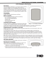
1164 FEATURES
Cover Latch
Test Button
Figure 1: 1164 Features
Red LED
Green LED
Cover
Base

1164/1164NS Installation and Programming Guide 3
PROGRAM THE 1164
When programming an 1164/1164NS smoke detector, refer to the appropriate panel
programming guide, as needed.
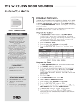
PROGRAMMER MENU
Enter 6653 (PROG) at the keypad to enter the PROGRAMMER
menu.
ZONE INFORMATION
Press CMD until ZONE INFORMATION displays. Press a select
key or area to enter the menu.
ZONE NUMBER
Enter the ZONE NO:.
ZONE NAME
Enter the ZONE NAME.
ZONE TYPE
Select FI (fire) as the ZONE TYPE.
PROGRAMMER
ZONE INFORMATION
ZONE NO:
ZONE NAME:
ZONE TYPE
FI EM PN

1164/1164NS Series Installation and Programming Guide 4
NEXT ZONE
At the NEXT ZONE? prompt, select NO.
WIRELESS ZONE
At the WIRELESS ZONE? prompt, select YES.
Note: If you are programming the smoke detector onto
a zone that can be either hardwired or wireless, then
this prompt appears. If the zone you are programming is
wireless-only, then the prompt does not appear.
SERIAL NUMBER
Enter the eight-digit SERIAL NO found on the device and press
CMD.
SUPERVISION TIME
Enter 3 as the SUPVSN TIME, and then press CMD.
NEXT ZONE
At the NEXT ZONE?, prompt, select NO.
NEXT ZONE? NO YES
WIRELESS ZONE? YES
SERIAL NO:
SUPVSN TIME: 3
NEXT ZN? NO

1164/1164NS Installation and Programming Guide 5
BELL OPTIONS
Press CMD until BELL OPTIONS displays, and then press a
select key or area.
FIRE BELL ACTION
At FIRE BELL ACTION FIRE TYPE:, select T (temporal) as the
action type.
Note: Program this option to enable cadence
synchronization with other 1164s on the system.
BELL OPTIONS
FIRE BELL ACTION...
FIRE TYPE: T

1164/1164NS Series Installation and Programming Guide 6
SELECT A LOCATION
Use the LED survey operation to select a proper location for the smoke detector. The LED
survey operation allows one person to confirm communication with the wireless receiver
or panel while the cover is removed. Because the smoke detector’s transmitter LED is not
visible, use a separate 1100 Series transmitter for the LED survey operation, such as the
1106 Universal Transmitter.
1. Hold the 1106 in the exact desired location.
2. Press the tamper switch on the 1106 to send data to the panel and determine if
communication is confirmed or faulty.
Confirmed: If communication is confirmed, for each press or release of the
tamper switch the LED blinks immediately on and immediately o.
Faulty: If communication is faulty, the LED remains on for up to eight
seconds or flashes multiple times in a quick succession. Relocate the wireless
receiver until the LED confirms clear communication.

1164/1164NS Installation and Programming Guide 7
INSTALL THE 1164
MOUNT THE BASE
After selecting a location, mount the smoke detector on a flat wall or ceiling. The
ensure optimum performance, mount the smoke detector away from large metal
objects. See Mounting Guidelines for more information.
1. Grasp the detector and twist counterclockwise to remove the detector from
the mounting base. See Figure 2.
2. Use the supplied screws and anchors to mount the base to the surface.
1
Figure 2: Remove
Detector from Base
Figure 3: Mounting
Hole Locations

1164/1164NS Series Installation and Programming Guide 8
ENABLE THE TAMPER SWITCH (OPTIONAL)
The 1164 features a tamper switch to send a trouble message to the panel if the
detector is removed from the mounting base. To enable the tamper switch, follow the
directions below:
1. Identify the small plastic tab that’s located on the mounting base.
See Figure 4.
2. Cut the tab o of the base. The tamper switch will take eect after the
detector is installed.
Note: After the tamper switch is enabled, a small screwdriver must be
used to depress the cover latch before the detector can be removed from
the base.
2
Locking Tab
Cover Latch
Figure 4: Mounting Base and Tamper Switch

1164/1164NS Installation and Programming Guide 9
INSTALL THE BATTERY
Observe polarity when installing the battery. Only
install new 3.0 V lithium batteries (Panasonic Model
CR123A or DMP Model CR123-FIRE). The typical
battery life expectancy is a least one year. Follow
the directions below to install the battery in the
1164:
1. Firmly grasp the battery pull-tab on the
smoke detector’s battery compartment and
remove it. See Figure 5.
2. Place the included battery into the battery
compartment in the detector. The green
and red LEDs located on the 1164 cover will
simultaneously flash four times, and then the green LED will flash every ten
seconds indicating the detector is in standby.
REPLACE THE COVER
After installing the battery, replace the cover back on the base. Follow the directions
below:
1. Place the detector on the base, aligning the raised tab on the detector’s lip
and the cover latch on the base’s lip.
2. Rotate the detector until it clicks into place.
3. Remove the orange plastic dust cover from the detector once installation (and
any surrounding construction) is complete.
3
Figure 5: Battery Location
Battery
Compartment
4

1164/1164NS Series Installation and Programming Guide 10
TEST THE 1164
Use a tool with a diameter of .018 inches or less to press the test button. If the smoke
detector is operating in it’s proper sensitivity limits and not in low battery condition, then
the green LED turns o and the red LED stays on continuously while the test button
is being pushed. Verify the control panel alarm and all auxiliary functions to perform a
complete test of the system. See Figure 6 and Table 1.
Figure 6: Test Button Location
0.18 inch tool to
press the test button
Green LED
Red LED
LED OPERATION
Green LED blinks
every 10 seconds
Standby
Red LED is steady
Smoke Detected
or Test Alarm
Red LED blinks
every 45 seconds
Low Battery
Red LED blinks
every 5 seconds
Maintenance
Needed
Table 1: LED Operation

1164/1164NS Installation and Programming Guide 11
TEST/SILENCE BUTTON
The Test/Silence button performs the following functions:
Testing: Pressing the Test/Silence button tests the functionality of the circuitry, proper
sensitivity limits, and battery condition. If pressed and held for 2.5 seconds or longer,
the sounder will be enabled (1164 only). When released, the sounder will silence (1164
only) and the detector returns to the state prior to the test button being pressed.
Additionally, when the Test/Silence button is pressed, the red LED turns on and remains
steady until the button is released.
Silence Alarm: (1164 only) When pressed during an alarm the sounder is disabled for
five minutes.
Silence Trouble Chirp: (1164 only) Press to silence a trouble chirp for 12 hours. If the
test button is pressed during the silence period, the detector will not respond. If an
alarm condition occurs during the silence period, the sounder will enable as per alarm
requirements. The trouble chirp resumes after 12 hours if the trouble condition is not
corrected.
SMOKE TESTING
Smoke detectors should be smoke tested in-place annually.
1. Hold a smoldering punk or cotton wick close to the smoke entry openings.
2. Direct the smoke into the detector for 20 seconds, or until the smoke detector
goes into alarm.
Caution: Remember to extinguish the smoke source after testing. The detector’s
red LED should stay on and the control panel should recognize an alarm. Use the
system reset switch to reset the detector.

1164/1164NS Series Installation and Programming Guide 12
CLEAN THE 1164
Smoke detectors must be maintained to meet NFPA 72 requirements. Smoke detectors
should be cleaned at least once per year.
Note: Before performing maintenance on the detector, notify the proper authorities that
the smoke detector will be temporarily out of service.
1. Remove the detector cover from the mounting base. See Figure 2.
2. Remove the battery from the detector. See Figure 5.
3. Use a vacuum or canned air to clean the detector.
4. Grasp the detector cap, gently twist to the left, and then lift up. See Figure .
5. Press in the sides of the sensing chamber where indicated by the alignment
arrows. Pull the sensing chamber straight up out of the detector. See Figure 8.
6. Use a vacuum or canned air to clean the sensing chamber.
7. Line up the arrows on the sensing chamber and the latches on the smoke
detector base, and then snap the sensing chamber back into place.
8. Replace the detector cap by lining up the new cap with the detector.
9. Insert the cap into the smoke detector and twist it gently to the left until it
snaps into place.
10. Reinsert the battery, and then reattach the detector to the mounting base.

1164/1164NS Installation and Programming Guide 13
Figure 7: Remove Detector Cap
Figure 8: Detector Cover and
Sensing Chamber

1164/1164NS Series Installation and Programming Guide 14
MOUNTING GUIDELINES
GENERAL GUIDELINES
In addition to NFPA 72, use the following location guidelines to optimize performance and
reduce false alarms. Refer to Figure 9.
• Place ceiling-mounted smoke detectors in the center of a room/hallway at least 4
inches from walls and partitions. If a ceiling is sloped, peaked, or gabled, place the
detector 3 feet from the highest-point. If mounting to suspended ceiling tile, the
tile must be secured with an appropriate fastener across ceiling panel supports.
• Place wall-mounted smoke detectors at least 4 inches below the ceiling.
• Mount smoke detectors on a firm, permanent surface.
• Place in environmentally-controlled areas with a temperature range between
40° and 100° F (4.4° and 37.8° C) and the humidity is between 0 and 90% non-
condensing.

1164/1164NS Installation and Programming Guide 15
AUTHORITY HAVING JURISDICTION
A proper location is critical to ensuring proper operation. Equipment should be installed in
accordance with the National Fire Protection Association’s (NFPA) Standard 72, Chapters,
2 and 8. You may need to reference other chapters of NFPA 72 or NFPA 101.
Smoke detector regulations vary from state to state, so contact the Authority Having
Jurisdiction (AHJ). Where public safety is primary, the AHJ may be a federal, state, local,
or other regional department or individual (such as a fire chief, fire marshal, chief of a fire
prevention bureau, labor or health department, building ocial, electrical inspector, or
others having statutory authority.
For insurance purposes, an AHJ may be an insurance inspection department, rating
bureau, or other insurance company representative. Sometimes, a property owner or
their designated agent assumes the role of the AHJ. At government installations, the
commanding ocer or department ocial may be the AHJ.

1164/1164NS Series Installation and Programming Guide 16
LOCATIONS TO AVOID
Smoke detectors should not be installed in or near the following locations:
• In/near areas where combustion particles are common (kitchens, garages,
furnaces, hot water heaters, or gas space heaters).
• On ceilings in rooms next to kitchens if there is no transom between the room and
the kitchen.
• In damp or humid areas, such as bathrooms with showers.
• In extremely cold or hot areas.
• In dusty, dirty, or insect-infested areas.
• Near air conditioners, heating registers, or any other ventilation source that may
interfere with smoke entering the detector.
• Near fresh air inlets/returns or excessively drafty areas (heating/air conditioning
vents, fans, etc.).
• In dead-air spaces at the top of peaked ceilings or corners where walls and ceiling
meet.
• Near fluorescent light fixtures (smoke detectors should be at least 10 feet away).
/