Page is loading ...

XR550 Series System
Testing Guide
LT-1687 17333
TABLE OF CONTENTS
Post-Installation Testing ................................. 2
Test Communication ............................................................ 2
Test Cellular Signal Strength .............................................. 3
Test Hardwired and Wireless Zones .................................. 3
Test Key Fobs ....................................................................... 4
Test Panel Batteries ............................................................. 4
Troubleshooting Testing.................................5
Perform a Walk Test ............................................................. 5
Use the Diagnostics Function ............................................ 7
Test the LX-Bus .............................................................................7
Check the Zone State ..................................................................7
Retrieve the LX-Bus Status ........................................................8

XR550 SERIES SYSTEM TESTING GUIDE | DIGITAL MONITORING PRODUCTS 2
Test Communication
The panel contains a Diagnostics function that allows you to test the communication integrity of the
LX-Bus™, identify individual zones, and display the present electrical state of any zone. The Diagnostics
function also allows you to test the integrity of cellular communication, cellular signal, and e-mail
communication.
Communication Status
To test the system’s communication status using the Diagnostics function, follow these steps:
1. Reset the panel.
2. Enter the Diagnostics code 2313 (DIAG) and press CMD.
3. Press CMD until COMM STATUS displays and then press any top row select key or area.
4. Enter the cellular or network PATH: number you would like to test. The test begins immediately and
displays the result. See the result sections below to determine whether the test succeeded or failed.
Cellular Results
Successful Display Failure Display
MODEM OPERATING NO MODEM FOUND
IDENTIFIED NO SIM CARD
TOWER DETECTED NO TOWER
REGISTERED NOT REGISTERED
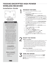
This displays the cellular signal strength of the nearest tower for the SIM card
carrier. The
▐
’s represent the signal strength 0-7. Select YES to continue
through the remaining component tests. Select NO to stop testing and return
to the COMM STATUS option.
Successful Display Failure Display
CONNECTED CONNECT ERROR
NOT ACTIVATED
COMM PATH GOOD NO ACK RECEIVED
Network Results
Successful Display Failure Display
LINK OK LINK ERROR
DHCP OK DHCP ERROR
GATEWAY FOUND NO GATEWAY
DEST FOUND NO DESTINATION
COMM PATH GOOD NOT CONNECTED
NO ACK RECEIVED
SIGNAL: ▐▐▐▐▐▐▐
CONTINUE? NO YES
POST-INSTALLATION
TESTING
After an XR550 Series system has been installed, perform the tests outlined in this section to ensure that
each element of the system is functioning properly.

XR550 SERIES SYSTEM TESTING GUIDE | DIGITAL MONITORING PRODUCTS 3
Test Cellular Signal Strength
To test the system’s cellular signal strength using the Diagnostics function, follow these steps:
1. Reset the panel.
2. Enter the Diagnostics code 2313 (DIAG) and press CMD.
3. Press CMD until CELL SIGNAL displays and then press any top row select key or area.
4. The SIGNAL: display shows how strong the cell signal is in bars and dBm. See the sections below to
determine the results of the test.
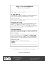
Cellular Signal Strength (CELL SIGNAL)
This option provides a way to test the cellular signal strength of the nearest tower for
the SIM card provider. Press any select key or area to display cell signal strength. The X’s
represent the numerical value of the cell signal strength in -dBm. The
▐
’s represent the
signal strength 0-7.
Cell Roaming Indicator (263C only)
The cellular signal strength option in the panel’s Diagnostic menu contains a roaming
indicator. When a 263C Cellular Communicator is roaming or not in contact with a
Verizon-owned tower, ROAM will be displayed on the top line of the keypad along with
the signal strength.
To perform the cellular activation process from a keypad, the 263C must be in contact
with a Verizon-owned tower. If the cellular communicator is in contact with a tower
owned by another network, ROAM and the signal strength displays, but activation cannot
be completed. This feature can be used as a diagnostic tool to troubleshoot activation
issues.
Test Hardwired and Wireless Zones
After you install and program a zone, arm and trip the zone to ensure that it successfully generates an alarm
message.
The following zone types have a specific Area that may need to be armed in order to result in an alarm
event.
• Night (NT)
• Day (DY)
• Exit (EX)
• Auxiliary 1 (A1)
• Auxiliary 2 (A2)
The following zone types do not have a specific Area that is required to be armed, and can be tripped at any
time.
• Panic (PN)
• Emergency (EM)
• Supervisory (SV)
• Fire (FI)
The following zones have other specific conditions that require consulting the panel’s programming to be
properly tested.
• Fire Verify (FV)
• Arming (AR)
-XX dBm
SIGNAL: ▐▐▐▐▐▐▐
ROAM -XX dBm
SIGNAL: ▐▐▐▐▐▐▐

XR550 SERIES SYSTEM TESTING GUIDE | DIGITAL MONITORING PRODUCTS 4
Test Key Fobs
Key fobs should be tested in the same manner as any other zone. If the key fob is programmed for a long
press, make sure it is depressed for the two second press time. When the button is programmed for Panic,
Panic 2, Emergency, Emergency 2, Output, or Sensor Reset, a half-second green flash occurs to acknowledge
the button press.
Test Panel Batteries
Individual panel batteries should be tested while they are disconnected from the charging circuit of the
panel, and disconnected from an array of multiple batteries. For proper testing, use a battery load tester.
Consult the instructions of your battery load tester to determine proper testing procedures.

XR550 SERIES SYSTEM TESTING GUIDE | DIGITAL MONITORING PRODUCTS 5
TROUBLESHOOTING
TESTING
Troubleshooting panel issues can be time-consuming if you don’t have access to the right information.
There are two main ways to use testing to find the right information - either perform a Walk Test or use
the Diagnostics function. These options may be used at any time and can be instrumental when you are
diagnosing the issue.
Perform a Walk Test
The panel provides a Walk Test feature that allows a single technician to test protection devices connected
to zones on the system. Conduct the Walk Test within 30 minutes of resetting the panel. The Walk Test
automatically ends if no zones are tripped for 20 minutes. TEST IN PROGRESS displays at all keypads
programmed with the same Display Areas features. When 5 minutes remain, TEST END WARNING displays.
The Walk Test only tests zones assigned to the areas programmed into the keypad in Display Areas. If any
areas are armed, the Walk Test does not start and SYSTEM ARMED displays.
Note: If the Panic Supervision option is enabled in SYSTEM OPTIONS, the panic button on any programmed
key fob can be tested during the Walk Test. When the panic button is pressed a verification message is sent
by the receiver.
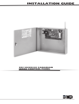
Walk Test
To conduct the Walk Test, reset the control panel by momentarily placing a
jumper on the RESET header. From the keypad, enter the code 8144.
The keypad displays WALK TEST for four seconds. If the system is monitored
and the communication type is DD or NET, the system sends a System Test
Begin report to the central station. After four seconds, the keypad displays the
zone type choices for testing.
Zone Types
Select the zone type you want to test. An asterisk next to the zone type
indicates the zone type chosen for testing. Press the select key or area again
to deselect the zone type. When you have selected all the zone types you want
for testing, press the CMD key to display the next Walk Test option. Pressing
the back arrow key exits the Walk Test.
Note: For the Wireless Check-in Test, make sure no zone types are selected
and press the CMD key. Pressing the back arrow key exits the Walk Test.
BG (Burglary zones) - Select BG to test burglary zones. Includes all NT, DY, EX,
A1, and A2 zones.
FI (Fire zones) - Select FI to test fire zones. Includes all FI and FV zones.
PN (Panic zones) - Select PN to test panic zones. Includes all PN and EM zones.
SV (Supervisory zones) - Select SV to test supervisory zones. Includes all SV
zones.
Note: During the Walk Test, trip each zone device or button on the system for
1 to 2 seconds. You do NOT have to hold the zones for 2 seconds in normal
mode for PN type zones. You are only required to hold the panic during the
Walk Test because the zone takes additional time to report when the system is
in test mode.
WLS (Wireless Check-in Test) - Select WLS to automatically test wireless
transmitter communications. Includes all wireless devices except key fobs and
transmitters programmed for a supervision time of 0 (zero).
PIR (Wireless PIR Walk Test) - The PIR Walk Test allows the installer to verify
WALK TEST
BG FI PN SV
WLS PIR

XR550 SERIES SYSTEM TESTING GUIDE | DIGITAL MONITORING PRODUCTS 6
the 1126 or 1127 operation. When enabled, the PIR LED flashes each time
motion is detected for up to 30 minutes. This is a local test only and no
messages are sent to the Central Station.
Bell Action
This option selects the bell output action when a zone under test faults. This
option allows the panel bell, and/or burglary bell, and/or fire bell to turn ON
and then OFF each time a zone is tripped (opened or shorted).
NO - Select NO for no bell output action during Walk Test.
YES - Select YES to turn on any bell output for 2 seconds during Walk Test.
PULS - Select PULS to turn on any bell output for 1/4 second during Walk Test.
Any LX-Bus device output turns on for 1.6 seconds due to the polling cycle.
Trip Counter For Walk Test
Once in the Walk Test, walk around and trip each protective device. Continue
tripping devices until the entire system is tested.
With each zone trip during the Walk Test:
• Keypad display increments each time a selected zone is opened or shorted
• The keypad buzzes for two seconds
• The panel sounds the alarm bells as programmed in Bell Action
• Each time a FI, FV, or SV zone trips, a Sensor Reset occurs.
If ENHANCED ZONE TEST is selected as YES:
A Verify message is sent at the time the zone trip occurs instead of at the end
of the Walk Test. For FI, FV or SV zone types, the Verify message is sent at the
initial trip.
For all other zone types, the Verify message is sent when the zone restores.
This allows the Central Station to count the number of devices per zone.
END - Select END to stop the Walk Test. When the Walk Test ends or a
20-minute time-out expires, a final Sensor Reset occurs. The System Test End
message is sent to the receiver along with Verify and Fail messages for each
zone under test. Faulted zones then display on the keypad.
Trip Counter for DMP Wireless Check-In Test (WLS)
Displays the number of wireless zones that automatically communicate a
supervision check-in message.
• The number of zones that check in. (XXX in the example).
• The total number of wireless zones programmed for supervision that should
check in. (ZZZ in the example).
END -
Select END to stop the Wireless Check-in Test. When the test ends or a
20-minute time-out expires, normal wireless zone processing returns. If all
transmitters check-in, both numbers match within three (3) minutes. If a
transmitter has multiple zones (1101, 1114, etc.), all zones are included in the
counts. Failed wireless zones display on the keypad.
Test End Warning
When five minutes remain on the 20 minute Walk Test timer, the keypad
displays TEST END WARNING. If no additional test zone trips occur, the test
ends and a final Sensor Reset automatically occurs. The System Test End
message is sent to the receiver along with Verify and Fail messages for each
zone under Walk Test. Faulted zones then display on the keypad.
Note: Key fobs do not send failure messages in order to prevent functioning
key fobs that are not present at the time of the test from being reported as
MISSING.
BELL NO YES PULS
TRIPS: XXX END
CKIN:XXX/ZZZ END
TEST END WARNING

XR550 SERIES SYSTEM TESTING GUIDE | DIGITAL MONITORING PRODUCTS 7
Failed Zones Display
For each zone that did not trip (failed), except key fobs, at least once during the
Walk Test, all keypads with matching Display Areas programming display the zone
name and number and buzz for one second. Any selected (*FI *PN *SV) 24-hour
zone that is faulted at the end of the Walk Test displays a trouble condition for that
zone regardless of the message programmed for the open or short condition of the
zone and a zone trouble is sent to the receiver. Press the CMD key to display the
next failed zone.
Note: For the Wireless Check-in Test, failed wireless zones display only on the
keypad. Zone Verify/Fail reports are not sent to the central station receiver for
the wireless check-in test.
Use the Diagnostics Function
The panel’s Diagnostics function (described in the Post-Installation Testing section of this guide) can also be
used to determine the system’s LX-Bus and zone statuses.
Test the LX-Bus
This function allows you to test the ability of the panel to communicate with zone and output expander
modules connected to the LX-Bus circuits.
Keep in mind, a device address is not the same as a zone number. If you are testing 714 or 715 Zone
Expander Modules, which each contain four zones, the device address is the first zone number. When the
panel polls a 714 on the LX-Bus, it recognizes it as a four zone device and does not poll the remaining three
zones. The 714 module internally polls the remaining zones and transmits any status changes to the panel.
This greatly reduces the amount of time it takes the panel to poll all LX-Bus devices.
1. Reset the panel.
2. Enter the Diagnostics code 2313 (DIAG) and press CMD.
3. Press CMD until TEST LX-BUS displays and press any select key or area.
4. The keypad displays LX-BUS:. Using the digit keys, enter the LX-Bus number, 1 to 5, to test that LX-Bus
circuit.
5. The keypad now displays ADDRESS: - . Enter a 2-digit LX-Bus device address and press CMD.
Note: When testing LX-Bus devices, enter only the addresses to which the modules have been set.
6. Press any select key or area when TEST LX-BUS displays.
7. The keypad displays TESTING . . . STOP during the device testing. At any time, you can select STOP
to end polling. The panel records the number of no responses from the device. If all polls are received
back by the panel correctly, the keypad displays 00000/65535 FAIL. If one or more polling attempts
fail, the keypad displays * * * * */65535 FAIL with the * representing the number of failed polling
attempts. A display of 65535/65535 FAIL indicates a problem with the interface card or its LX-Bus
wiring such as a bad or broken wire, harness not properly connected, or excessive noise or distance. It
can also mean that a zone number was entered that did not match a device address.
8. Press the back arrow key to enter a new device address or press CMD to exit the TEST LX-BUS.
Check the Zone State
This function allows you to enter any zone number and check its current electrical state (normal, open, or
shorted). To check a zone’s state using the Diagnostics function, follow these steps:
1. Reset the panel.
2. Enter the Diagnostics code 2313 (DIAG) and press CMD.
3. Press CMD until ZONE STATE displays. Press any select key or area.
4. The display changes to ZONE NUMBER:. Enter in the zone number you want to check and press CMD.
5. The panel displays the current state of the zone as NRML (normal), OPEN, or SHORT.
SOUTH LOBBY
ZONE: 10 -FAIL

Designed, engineered, and
manufactured in Springfield, Missouri
INTRUSION • FIRE • ACCESS • NETWORKS
2500 North Partnership Boulevard
Springfield, Missouri 65803-8877
800-641-4282 | dmp.com
© 2017 Digital Monitoring Products, Inc.
LT-1687 17333
Retrieve the LX-Bus Status
This function allows the panel to poll all devices connected to the LX-Bus of an interface card and check for
any overlapped, missing, or extra addresses. To retrieve the system’s LX-Bus status using the Diagnostics
function, follow these steps:
1. Reset the panel.
2. Enter the Diagnostics code 2313 (DIAG) and press CMD.
3. Press CMD until LX-BUS STATUS displays and press any select key or area.
4. When OVLP MIS EXT displays, choose the type of status test you would like to run. See the definitions
below for more information.
Overlap (OVLP)
An overlap occurs when one device address is the same as any of the last three zones on another 714 or 715.
The overlap feature cannot determine when two devices have the same address.
Example: Model 714 Address 00 = Zones 500 501 502 503, and the Model 711 Address 02 = Zone 502.
Zone 502 would report as an overlap because both the 714 and 711 have devices set to 502.
Missing (MIS)
A missing occurs when a zone between 500 and 999 has been programmed in ZONE INFORMATION and
no device with that zone address has been installed on the LX-Bus. To correct the problem, check your zone
programming and zone expansion module addressing.
Extra (EXT)
A device is extra if it is installed on the LX-Bus, but none of its zones are programmed into the system.
/