Page is loading ...

Page 1
©1999 Whelen Engineering Company Inc.
Form No.13424C (052400)
Automotive: Lightbars
For warranty information regarding this product, visit www.whelen.com/warranty
• Proper installation of this product requires the installer to have a good understanding of automotive electronics, systems and procedures.
• Whelen Engineering requires the use of waterproof butt splices and/or connectors if that connector could be exposed to moisture.
• Any holes, either created or utilized by this product, should be made both air- and watertight using a sealant recommended by your vehicle
manufacturer.
• Failure to use specified installation parts and/or hardware will void the product warranty.
• If mounting this product requires drilling holes, the installer MUST be sure that no vehicle components or other vital parts could be damaged
by the drilling process. Check both sides of the mounting surface before drilling begins. Also de-burr the holes and remove any metal shards
or remnants. Install grommets into all wire passage holes.
• If this manual states that this product may be mounted with suction cups, magnets, tape or Velcro®, clean the mounting surface with a 50/50
mix of isopropyl alcohol and water and dry thoroughly.
• Do not install this product or route any wires in the deployment area of your air bag. Equipment mounted or located in the air bag deployment
area will damage or reduce the effectiveness of the air bag, or become a projectile that could cause serious personal injury or death. Refer to
your vehicle owner’s manual for the air bag deployment area. The User/Installer assumes full responsibility to determine proper mounting
location, based on providing ultimate safety to all passengers inside the vehicle.
• For this product to operate at optimum efficiency, a good electrical connection to chassis ground must be made. The recommended
procedure requires the product ground wire to be connected directly to the NEGATIVE (-) battery post (this does not include products that use
cigar power cords).
• If this product uses a remote device for activation or control, make sure that this device is located in an area that allows both the vehicle and
the device to be operated safely in any driving condition.
• Do not attempt to activate or control this device in a hazardous driving situation.
• This product contains either strobe light(s), halogen light(s), high-intensity LEDs or a combination of these lights. Do not stare directly into
these lights. Momentary blindness and/or eye damage could result.
• Use only soap and water to clean the outer lens. Use of other chemicals could result in premature lens cracking (crazing) and discoloration.
Lenses in this condition have significantly reduced effectiveness and should be replaced immediately. Inspect and operate this product
regularly to confirm its proper operation and mounting condition. Do not use a pressure washer to clean this product.
• It is recommended that these instructions be stored in a safe place and referred to when performing maintenance and/or reinstallation of this
product.
• FAILURE TO FOLLOW THESE SAFETY PRECAUTIONS AND INSTRUCTIONS COULD RESULT IN DAMAGE TO THE PRODUCT OR VEHICLE
AND/OR SERIOUS INJURY TO YOU AND YOUR PASSENGERS!
Warnings to Installers
Whelen’s emergency vehicle warning devices must be properly mounted and wired in order to be effective and safe. Read and follow all of Whelen’s written
instructions when installing or using this device. Emergency vehicles are often operated under high speed stressful conditions which must be accounted for
when installing all emergency warning devices. Controls should be placed within convenient reach of the operator so that they can operate the system without
taking their eyes off the roadway. Emergency warning devices can require high electrical voltages and/or currents. Properly protect and use caution around
live electrical connections.Grounding or shorting of electrical connections can cause high current arcing, which can cause personal injury and/or vehicle
damage, including fire. Many electronic devices used in emergency vehicles can create or be affected by electromagnetic interference. Therefore, after
installation of any electronic device it is necessary to test all electronic equipment simultaneously to insure that they operate free of interference from other
components within the vehicle. Never power emergency warning equipment from the same circuit or share the same grounding circuit with radio
communication equipment. All devices should be mounted in accordance with the manufacturer’s instructions and securely fastened to vehicle elements of
sufficient strength to withstand the forces applied to the device. Driver and/or passenger air bags (SRS) will affect the way equipment should be mounted. This
device should be mounted by permanent installation and within the zones specified by the vehicle manufacturer, if any. Any device mounted in the deployment
area of an air bag will damage or reduce the effectiveness of the air bag and may damage or dislodge the device. Installer must be sure that this device, its
mounting hardware and electrical supply wiring does not interfere with the air bag or the SRS wiring or sensors. Mounting the unit inside the vehicle by a
method other than permanent installation is not recommended as unit may become dislodged during swerving; sudden braking or collision. Failure to follow
instructions can result in personal injury. Whelen assumes no liability for any loss resulting from the use of this warning device. PROPER INSTALLATION
COMBINED WITH OPERATOR TRAINING IN THE PROPER USE OF EMERGENCY WARNING DEVICES IS ESSENTIAL TO INSURE THE SAFETY OF
EMERGENCY PERSONNEL AND THE PUBLIC.
Warnings to Users
Whelen’s emergency vehicle warning devices are intended to alert other operators and pedestrians to the presence and operation of emergency vehicles and
personnel. However, the use of this or any other Whelen emergency warning device does not guarantee that you will have the right-of-way or that other
drivers and pedestrians will properly heed an emergency warning signal. Never assume you have the right-of-way. It is your responsibility to proceed safely
before entering an intersection, driving against traffic, responding at a high rate of speed, or walking on or around traffic lanes. Emergency vehicle warning
devices should be tested on a daily basis to ensure that they operate properly. When in actual use, the operator must ensure that both visual and audible
warnings are not blocked by vehicle components (i.e.: open trunks or compartment doors), people, vehicles, or other obstructions. It is the user’s responsibility
to understand and obey all laws regarding emergency warning devices. The user should be familiar with all applicable laws and regulations prior to the use of
any emergency vehicle warning device. Whelen’s audible warning devices are designed to project sound in a forward direction away from the vehicle
occupants. However, because sustained periodic exposure to loud sounds can cause hearing loss, all audible warning devices should be installed and
operated in accordance with the standards established by the National Fire Protection Association.
Safety First
This document provides all the necessary information to allow your Whelen product to be properly and safely installed. Before beginning the installation and/or
operation of your new product, the installation technician and operator must read this manual completely. Important information is contained herein that could
prevent serious injury or damage.
Installation Guide:
Micro Edge® Lightbar
(with ISP4HS Power Supply)
51 Winthrop Road
Chester, Connecticut 06412-0684
Phone: (860) 526-9504
Internet: www.whelen.com
Sales e-mail: autosale@whelen.com
Customer Service e-mail: [email protected]
®
ENGINEERING COMPANY INC.

Page 2
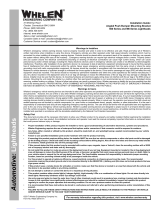
Fig. 5
Fig. 3
Fig. 4
Wire
Tie
Micro-Edge
Mounting
Bracket
Extension
Flange
Mirror
Bracket
U-Bolt
Fig. 1
Mounting the Micro-Edge Strobe:
IMPORTANT! The lightbar should be located a
minimum of 16" from any radio antennas!
Two Whelen Micro-Edge Strobe lights are
included in this lighting system. The mirror mount
brackets shown are purchased seperately. (See
parts list) Begin the mounting procedure by
loosely assembling the mounting bracket (Fig.1).
Position this partial assembly on the mirror
bracket as shown in Fig. 2. Mount the assembly to
the mirror bracket using the U-Bolt hardware
supplied with the brackets (Fig. 3). Insert the
mounting bolt on the Micro-Edge through the hole
provided in the extension flange. Secure as
shown in Fig. 3. Adjust the bracket assembly until
the Micro-Edge is properly aligned and tighten the
bracket bolts firmly. Repeat entire procedure for
the remaining door.
Fig. 2
Wiring the Micro-Edge Strobe:
The Micro-Edge harness cable must now be routed to the power supply. The path the
harness cable follows will vary, depending upon where the power supply has been
mounted. If the power supply has been mounted against the rear cab wall, the path would
be:
1. Secure harness cable to Micro-Edge mounting bracket with heavy-duty wire ties (Fig.
4)
2. Now have the harness cable follow the factory mirror bracket to the point where the
bracket meets the vehicle door. Secure the cable with heavy-duty wire ties.
3. Remove the interior door panel. When you are sure that no door components will be
damaged, drill a hole in the door just below the point where the factory mirror bracket
connects to the door. Insert a rubber grommet to prevent water leakage.
4. Insert the harness cable through the hole and route it towards the door’s hinge panel.
Drill a hole in the hinge panel and insert the harness cable. Be sure that the cable
does not interfere with the movement of any door or window components (Fig. 5).
5. Route the cable into the cab through the kick panel and then under the rocker panel
molding toward the back of the cab. Make sure that the harness cable does not bind
up when the door is opened and closed.
IMPORTANT: The outer surfaces of this light may be cleaned with mild soap and water.
Use of any other chemicals may void product warranty. Do not use a pressure washer.

Page 3
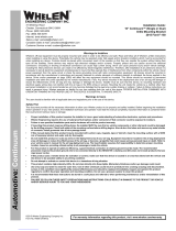
NO CONNECTION
CUT FLUSH WITH
CABLE JACKETING
NO CONNECTION
CUT FLUSH WITH
CABLE JACKETING
NO CONNECTION
NO CONNECTION
#2 #8
HALOGEN
#1 #7
STROBE
#5
#3
STROBE
#6 #4
HALOGEN
TOP VIEW OF LIGHTHEADS
WHITE
WHITE/VIOLET
BLACK
RED
WHITE/BLACK
GRAY
WHITE/BLUE
BLACK/WHITE
BLACK/YELLOW
YELLOW
VIOLET
DRAIN WIRE
VIOLET
WHITE
BLACK / WHITE
BLACK / YELLOW
WHITE / VIOLET
BLACK
RED
YELLOW
WHITE / BLACK
GRAY
WHITE / BLUE
VIOLET
DRAIN WIRE
WHITE / VIOLET
BLACK
RED
WHITE
WHITE / BLACK
GRAY
WHITE / BLUE
BLACK / WHITE
BLACK / YELLOW
YELLOW
YELLOW
BLACK / YELLOW
BLACK/WHITE
WHITE / BLUE
GRAY
WHITE / BLACK
WHITE
RED
BLACK
WHITE / VIOLET
DRAIN WIRE
VIOLET
2
3
1
2
3
1
2
3
1
2
3
1
2
3
1
2
3
1
2
3
1
2
3
1
2
3
1
#1 #2
#6#5 FRONT
REAR
1
3
2
1
3
2
1
3
2
1
3
2
#7#8
#4
#3
FRONT
REAR
1
3
2
1
3
2
1
3
2
1
3
2
2
3
1
2
3
1
2
3
1
2
3
1
2
3
1
2
3
1
2
3
1
DRAIN WIRE
WARNING: The strobe power supply isahighvoltage device.Do not remove strobetubes or dismantlethe strobe lighthead
assembly while inoperation. Wait 10 minutes after turning off power before starting anywork or troubleshooting.
WARNING: All customer supplied wires that connect to the pos
itive terminal of the battery, must besized to supply at least 125%
of the maximum operating current, and fused at the battery to carry that load.
B
D
C
F
A
E
G
H
IMPORTANT: DO NOT INSTALL HALOGEN
BULBS EXCEEDING 20 WATTS
Replacing Strobe Assembly:
1. Remove the four screws (A) holding the endcap (B) on and pull
the endcap and gasket (C) off, then slide the lenses (D) out to gain
access to the multi-reflector assembly.
2. Unscrew the two nuts (F) & (E) from the two mounting bolts,
then unscrew the two mounting screws (G) that secure the
multi-reflector assembly to the lightbar.
3. Slide the assembly (H) out and unplug it from the lightbar.
4. Plug the new strobe assembly in and
slide it into the lightbar, then secure
it with the four mounting
screws.
5. Reassemble and
test the light.

Page 4
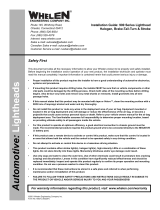
DESCRIPTION
ITEM
21
20
19
18
17
16
15
13
12
10
9
8
7
6
3
2
1
4
5
11
14
#10-24 X 1" TORX HEAD
ENDCAP / AMBER
"I" BEAM CENTER BRACKET
#4 X 1 PPHSMS/WASHER HEAD
"MADE IN USA" LABEL
#6-32 WHIZ NUT
LIGHTHEAD MOUNTING BRACKET
LAMPHOLDER ASSEMBLY / 12V-20W
AMP 3 SOCKET HOUSING
MICRO-EDGE "SNF" EXTRUSION
CABLE CLAMP / SHC-26
LENS / AMBER / 5.500"
AMP 3 PIN HOUSING
3/4" GROMMET
11/C W/PINS & SOCKETSCABLE ASSEMBLY
SYSTEM / MICRO-EDGE "SSNF" w/DIAGNOSTICS
POWER S
UPPLY / MODEL ISP4HS WITH DIAG.
ENDCAP GASKET
1/4" THK X 3/8" W X 2.75" LONG GASKET
MICRO EDGE "SNF" STROBE ASSEMBLY
MOUNTING BRACKET ASSEMBLY
GROMMET 1.00"
PART NUMBER
14-104286-16J
68-1181528-10
07-242198-000
15-041816-160
10-0320776-00
13-062111-053
07-241014-000
34-0041987-04
39-0403023-04
11-342643-000
26-0121053-01
68-1183080610
39-0403013-04
21-11202404-0
46-0742650-25
01-0683305-00
01-0662799-01
38-0261131-00
38-0316275-00
02-0363022-00
02-038132309S
21-11263204-0
*
QTY.
8
2
2
4
2
8
2
4
4
8
4
2
2
4
16
1
2
4
2
4
2
3
4
7
6
5
12
11
10
22
9
21
20
2
9
10
11
12
13
14
16
15
8
18
19
17
W
H
ELEN
D
IA
G
N
O
STIX
1
22
#6-32 X PPHMS
14-062216-160
4
-
MIRROR MOUNTING KIT
01-0362332-00
N/A
/