Page is loading ...

Page 1 of 5
Johnson Controls Denmark ApS
Christian X's Vej 201 ∙ 8270 Højbjerg ∙ Denmark
Phone +45 87 36 70 00 ∙ Fax +45 87 36 70 05 ∙ www.sabroe.com
CVR No 19 05 61 71
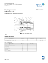
Mounting instruction 06 August 2018
011268 (replaces 0171-978)
First version: September 2014 – same content as in the original release from 2002.
Second version: August 2018 – changes in some of the part numbers.
This Mounting instruction must be incorporated in the compressor instruction manual.
Alteration of shaft seal on R5 screw compressors (Generation “P”)
As announced in Technical Information TI2001/07, a new shaft seal system ensuring improved lubricating and cool-
ing conditions for the shaft seal in the above screw compressors was introduced in August 2001.
It is still the same shaft seal construction which is used, part no. 1332.188, but the shaft seal has been turned up-
side down so that the flexible part pos. 8d (the one with the bellows) is now rotating with the motor shaft. The slide
ring pos. 8a is mounted in the stationary retaining ring, pos. 4, as illustrated in the drawing Fig. 1.
Moreover, the oil flow around the shaft seal has been changed so that the cooled oil flows directly against the sliding
surfaces of the shaft seal in order to achieve the most effective cooling.
Oil outlet from the shaft seal housing has been moved higher up to ensure that no refrigerant gas is collected at the
shaft seal, which can prevent effective cooling.
Another important improvement is that the two V-rings, pos. 1 Fig. 3, have been replaced by a lip seal, pos. 1, see
Fig. 1 and Fig. 2.

Page 2 of 5
Johnson Controls Denmark ApS
Christian X's Vej 201 ∙ 8270 Højbjerg ∙ Denmark
Phone +45 87 36 70 00 ∙ Fax +45 87 36 70 05 ∙ www.sabroe.com
CVR No 19 05 61 71
Fig. 1
Fig. 2
1
10
5
1 1
2
3
18
4
8
6
8c
14
13
9
7
8d
Oil inlet
8b
8a
17
C
C
14
13
1 1
9
7
8
6
10
5
4
3
1
2
18
SECTIONC--C
16

Page 3 of 5
Johnson Controls Denmark ApS
Christian X's Vej 201 ∙ 8270 Højbjerg ∙ Denmark
Phone +45 87 36 70 00 ∙ Fax +45 87 36 70 05 ∙ www.sabroe.com
CVR No 19 05 61 71
Fig. 3
Alteration set, part no. 3084.724
The alteration set includes the following parts, marked in the drawings in Fig. 1 and Fig. 2:
Pos. no. Description Part no. Quantity
1 Complete sealing ring 3084.596 1
2 O-ring ID114.5x3.0 3921 5282 435 1
3 O-ring ID119.5x3.0 3921 5282 436 1
4 Seat holder 3026.058 1
5 Ring 1904 791-1 1
6 Slide ring 1940 298-1 1
7Grub screw 1413.212 1
8 Shaft seal 1332.188 1
9 O-ring ID64.5x3.0 1331.484 2
10 Tubular pin Dia. 3x10 3921 1171 205 1
11 Carrier 3026.059 1
13 Locking washer 3921 5415 165 8
14 Hexagon socket head screw 1413.359 4
16 Injection pipe 1905 781-A 1
17 Plug NPT 3951 3156 802 1
18 O-ring ID9,1x1,6 1331.2008 1
45 Washer 1901 449-3 1
100 Gasket 1902 223-1 1
104 Screw 1413.359 4
114 Locking washer 3921 5415 165 8
116 Plain washer 3921 5121 173 24
Dismounting of shaft seal
The compressor and the shaft seal are dismounted as described in the Instruction Manual, section 5.
Mounting of new shaft seal system
Prior to mounting the shaft seal system, all surfaces must be carefully cleaned and lubricated. Use the same oil type
as for operation of the compressor.
Proceed as follows:
1

Page 4 of 5
Johnson Controls Denmark ApS
Christian X's Vej 201 ∙ 8270 Højbjerg ∙ Denmark
Phone +45 87 36 70 00 ∙ Fax +45 87 36 70 05 ∙ www.sabroe.com
CVR No 19 05 61 71
• Mount the O-ring, pos. 2, on the part, pos. 1, (this part consists of the sealing ring and the retaining ring, see
Fig. 1 and Fig. 2, which have been fitted together from factory), and place the arrangement carefully on the
motor shaft without damaging the sealing surface of the sealing ring.
• Mount the following in the seat holde,r pos. 4:
Mount the pin, pos. 10, so that the max. height is 1.5 mm as shown in Fig. 4.
Press the ring, pos. 5, into place with a distance of 2 mm from the end surface (see Fig. 4).
Mount the stationary seat, pos. 8a, and the O-ring, pos. 8b, from the shaft seal, turning the slide ring so
that the groove catches the pin, pos. 10.
Mount the slide ring, pos. 6.
Mount the injection pipe, pos. 16, as shown in Fig. 2, section c-c, ensuring that the two injection holes
face the gearwheel, which is mounted later.
Mount the O-ring, pos. 3.
Fig. 4
• Place the seat holder which is now complete on the motor shaft. Make sure that the O-ring, pos. 18, is
placed as shown in Fig. 1. Tighten the seat holder by means of the locking washing, pos. 13, and the
screws, pos. 14.
Note: Use two locking washers for each screw.
• Mount and tighten the grub screw, pos. 7, in the carrier, pos. 11, and fit the O-ring, pos. 8c. Place the rotat-
ing part of the shaft seal in the carrier, pos. 11. Make sure that the grub screw catches the carrier hole.
• With the two O-rings, pos. 9, mounted, the complete arrangement is carefully placed on the motor shaft
without damaging the sliding surfaces of the shaft seal.
• Mount key and gearwheel, and tighten with washer and screw as described in the Instruction Manual.
Now proceed with the mounting procedure described in the Instruction Manual (to use the other parts of the altera-
tion set, pos. 45 to 116).
5
2
1,5
4
10

Page 5 of 5
Johnson Controls Denmark ApS
Christian X's Vej 201 ∙ 8270 Højbjerg ∙ Denmark
Phone +45 87 36 70 00 ∙ Fax +45 87 36 70 05 ∙ www.sabroe.com
CVR No 19 05 61 71
Erhardt Nielsen
Manager, Screw and Reciprocating Compressors
Technical Support and Development
Direct no.: +45 87 36 77 20
Fax no.: +45 87 36 77 05
E-mail: [email protected]
/