Page is loading ...

CM SP
Self-priming
Service instructions
GRUNDFOS INSTRUCTIONS

English (GB)
2
English (GB) Service instructions
Original service instructions.
CONTENTS
Page
1. Symbols used in this document
2. Identification
This section shows the nameplate, the type key and the codes
that can appear in the variant code.
The pump and motor nameplates are positioned on the motor fan
cover or terminal box. The data and information on the pump
nameplate are described in the table below.
2.1 Nameplate
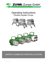
2.1.1 Pump nameplate
Fig. 1 Pump nameplate
2.1.2 Motor nameplate
Fig. 2 Motor nameplate
1. Symbols used in this document
2
2. Identification
2
2.1 Nameplate
2
2.2 Type key
3
3. Tightening torques and lubricants
4
4. Service tools
5
4.1 Standard tools
5
4.2 Torque tools
5
5. Dismantling and assembly
6
5.1 General information
6
5.2 Dismantling the pump
6
5.3 Assembling the pump
7
5.4 MG 71 and MG 80 motors
8
5.5 MG 90, MG 100, MG 112 and MG 132 motors
8
5.6 Checking and replacing impellers and chambers
9
6. Fault finding
10
7. Drawings
12
7.1 CM SP 1, 3, 5
12
8. Order of assembly for chambers and impellers
13
Warning
If these safety instructions are not observed,
it may result in personal injury.
Caution
If these safety instructions are not observed,
it may result in malfunction or damage to the
equipment.
Note
Notes or instructions that make the job easier
and ensure safe operation.
Note
As codes can be combined, a code position may
contain more than one code (letter).
TM04 0355 0908
Pos. Description
1 Pump type
2 Pump model
3
Environmental rating for enclosures based on NEMA
type designations
4 Enclosure class
5 Maximum ambient temperature [°C] / [°F]
6 Maximum system pressure [bar] / [psi] / [MPa]
7 Maximum liquid temperature [°C] / [°F]
8 Insulation class
9 Motor protection
10 Rated flow [m
3
/h] / [GPM]
11 Head at rated flow [m] / [psi]
12 Maximum head [m] / [psi]
TM04 0356 0908
Pos. Description
1 Number of phases
2 Voltage [V]
3 Maximum current [A]
4 Rated current [A]
5 Power output [kW] / [hp]
6
Single-phase pumps only:
Capacitor size [F] and voltage [V]
Model
IP
T
Type
P
max
T
liq,max
bar
MPa
PSI
Q
nom
H
nom
H
max
m³/h GPM
Env
m
m
PSI
PSI
Q
nom
H
nom
H
max
m³/h GPM
m
m
PSI
PSI
°C
°F
50 Hz
95120839
60 Hz
3
4
5
5
6
7
7
8
9
10 10
11 11
12 12
6
6
1
10
11
12
10
11
12
2
Amb
°C
°F
Insulation class
I max
~/V
/A
/A
uF / V
kW
95120836
I 1/1
P2
I max
~/V
/A
/
A
I 1/1
P2
Capacitor
HP kW HP
uF / V
Capacitor
50 Hz 60 Hz
112
3
4
5
2
3
4
5
2
3
4
5
2
3
4
5
6 6

English (GB)
3
2.2 Type key
Note: Other supply voltages, shaft seal combinations and pipe connections are available on request.
Stainless steel EN 1.4401/AISI 316 is also available on request.
Example CM 3 - 6 O - R - I - E - A V B E C - A - A - N
Type range Sensor
CM: Centrifugal Modular N: No sensor
Rated flow rate Mains plug
Rated flow rate at 50 Hz [m
3
/h] A: Prepared for cable glands
Number of impellers Motor information
Pump version A: Standard motor (IP55)
O: Self-priming version (max. suction lift, 8 metres) Supply voltage
S: Self-priming version (max. suction lift, 4 metres) A: 1 x 220 V, 60 Hz
Pipe connection C: 1 x 220-240 V, 50 Hz
R: Whitworth thread, Rp (ISO 7/1) Material of secondary seal
Materials in contact with pumped liquid E: EPDM (ethylene propylene)
I: Sleeve EN 1.4301/AISI 304 Material of stationary seat
Pump shaft EN 1.4301/AISI 304 B: Carbon, resin-impregnated
Impellers/chambers EN 1.4301/AISI 304 Q: Silicon carbide (SiC)
Rubber parts in pump (excluding neck ring and shaft seal) Material of rotating seal face
E: EPDM (ethylene propylene) Q: Silicon carbide (SiC)
V: Aluminium oxide (AI203)
Shaft seal
A: O-ring seal with fixed driver
Note
The type key cannot be used for ordering, as not all combinations are possible.

English (GB)
4
3. Tightening torques and lubricants
THREAD-EZE, product number 00SV9997 (0.5 l).
Rocol Sapphire Aqua-Sil, product number 00RM2924 (0.5 kg).
Castrol LMX grease, product number 00RM4311.
Silicone oil, 350 cSt, food grade 00SV0862 (1 l).
Pos. Designation Quantity Dimensions Torque [Nm] Lubricant
5c O-ring 1 ∅37 x 2.62 Sapphire Aqua-Sil
11 O-ring 2 ∅18.5 x 2.0 - -
25 Plug 2 - 10 - 12 -
26 Staybolt, CM 1, 3, 5, stainless steel 4 M8 12 - 14 THREAD-EZE
28g Screw 4 M6 x 14 8 - 10 THREAD-EZE
31 O-ring, CM 1, 3, 5 1 ∅114.0 x 3.90 - Sapphire Aqua-Sil
64f Rubber seal 1 Sapphire Aqua-Sil
67 Locking nut 1 M8 16 - 18 -
102 O-ring 1 ∅17.86 x 2.62 - V7140084
103 Seal faces 1 - -
Silicone oil, 350 cSt,
food grade
107 O-ring 1 ∅11.5 x 3.18 - Sapphire Aqua-Sil
152 Screw
2 M4 x 8 2.7 - 3.3 -
4 M5 x 12 3.5 - 4 -
155 Bearing cover plate 1 - - Sapphire Aqua-Sil
157a
Gasket, MG 71, MG 80 1 ∅114.8 / 121.2 x 0.25 - -
Gasket, MG 90 2 ∅141.2 / 145.5 - -
Gasket, MG 100 - - - -
158a O-ring 1 ∅35.4 x 1.97 - Sapphire Aqua-Sil
159
O-ring, MG 71, MG 80 1 ∅32 x 2
- Sapphire Aqua-SilO-ring, MG 90, MG 100 1 ∅52 x 3.0
O-ring, MG 112, MG 132 1 ∅62 x 3.0
159a Seal ring 1 - - Castrol LMX grease
181
Screw, MG 71, MG 80 4 M6 x 16 5 - 8
THREAD-EZE
Staybolt, MG 90 4 M5 x 220
4.5 - 6
Staybolt, MG 90L 4 M5 x 260
Staybolt, MG 100 4 M5 x 270
Staybolt, MG 112 4 M6 x 288

English (GB)
5
4. Service tools
4.1 Standard tools
4.2 Torque tools
ABCD
EFGH
IJKL
MN
Pos. Designation For pos. Further information Product number
A Screwdriver 103, 156 - SV0803
B Cross-head screwdriver 181 Ph2 x 100 SV0279
C Torx screwdriver J TX30 x 115 mm SV0335
D Ring/open-end spanner
64c 15 mm -
67 13 mm SV0055
E Hexagon key 26
5 mm -
6 mm SV0196
F Puller for bearing 153, 154 - -
G Plastic hammer 156 - SV0349
H Ratchet handle 156 - 96777072
I Hexagon head driver
26
M6 - 5 mm SV0296
M8 - 6 mm SV0297
181 M5 - 4 mm -
J Bits kit 28g, 152, 181 - SV2010
Pos. Designation For pos. Further information Product number
K Torque screwdriver J 1-6 Nm SV0438
L Ring insert tool N 13 mm - 9 x 12 mm SV0294
M Ratchet insert tool I 9 x 12 mm - 1/2" SV0295
N Torque wrench L, M
9 x 12 mm - 4-20 Nm SV2092
9 x 12 mm - 20-100 Nm SV0269

English (GB)
6
5. Dismantling and assembly
5.1 General information
If it is necessary to dismantle the pump, either because it is
choked or damaged, please follow the instructions in the following
sections.
Position numbers of parts (digits) refer to section 7. Drawings;
position numbers of tools (letters) refer to section 4. Service
tools.
Before dismantling the pump
• Disconnect the power supply to the motor.
• Close the isolating valves, if fitted, to avoid draining the
system.
• Remove the electric cable in accordance with local
regulations.
Before assembling the pump
• Clean and check all parts.
• Replace defective parts by new parts.
• Order the necessary service kits.
• Gaskets and O-rings should always be replaced when the
pump is overhauled.
During assembly
Lubricate and tighten screws and nuts to correct torque.
See section 3. Tightening torques and lubricants.
5.2 Dismantling the pump
1. Remove staybolts (pos. 26).
2. Remove clamping flange (pos. 6a) and sleeve (pos. 16).
3. Remove O-ring (pos. 5c) and water trap (pos. 5b).
4. Remove the two empty chambers (pos. 4f).
5. Remove valve chamber (pos 4e).
6. Remove spring valve (pos. 5e and 5d) from valve chamber
(pos. 4e).
7. Remove spring (pos. 5e) from base (pos. 5d).
8. Hold clamp (pos. 64c), and remove nut (pos. 67) by using
both tools D.
9. Remove lock washers (pos. 66) and clamp (pos. 64c).
10. Remove impeller (pos. 49).
11. Remove chambers (pos. 4).
12. Remove spacing pipe (pos. 64).
13. Continue the dismantling until short spacing pipe (pos. 64a),
rubber seal retainer (pos. 64g) and rubber seal (pos. 64f), and
remove those components.
14. Remove impeller (pos. 49), air separator chamber (pos 4d)
and spacing pipe (pos. 64).
15. Remove shaft seal (pos. 105). See fig. 3.
Fig. 3 Exploded view of shaft seal
16. Remove O-ring (pos. 31) and cover plate (pos. 32).
TM04 4327 1909
Note
Dismantling of MG 71 and MG 80, see section
5.4.1 Dismantling the motor.
Dismantling of MG 90 and MG 100, see section
5.5.1 Dismantling the motor.

English (GB)
7
5.3 Assembling the pump
1. Fit cover plate (pos. 32) and O-ring (pos. 31). Lubricate the
O-ring. See section 3. Tightening torques and lubricants.
2. Fit O-ring (pos. 102) on stationary seat. See fig. 4.
Lubricate the O-ring. See section 3. Tightening torques and
lubricants.
Fig. 4 Fitting the O-ring on the stationary seat
3. Press stationary seat (pos. 103) home.
4. Fit rotating seal face (pos. 104) so that the seal face touches
the stationary seat (pos. 103).
5. Fit O-ring (pos. 107) in rotating seal face (pos. 104).
Lubricate the O-ring. See section 3. Tightening torques and
lubricants.
6. Fit retainer (pos. 111) and stop ring (pos. 111a). See fig. 5.
Fig. 5 Fitting stop ring
7. Fit spring (pos. 108) and driver (pos. 112). See fig. 6.
Fig. 6 Fitting spring and driver
8. Fit air separator chamber (pos. 4d), spacing pipe (pos. 64)
and impeller (pos. 49).
9. Fit rubber seal (pos. 64f) in rubber seal retainer (pos. 64g)
and impeller (pos. 49), and slide it on the shaft.
10. Fit short spacing pipe (pos. 64a).
11. Fit remaining spacing pipes (pos. 64), chambers (pos. 4) and
impellers (pos. 49).
12. Fit clamp (pos. 64c), lock washers (pos. 66) and nut (pos. 67).
See fig. 7.
Fig. 7 Correct fitting of lock washers
13. Hold clamp (pos. 64c), and tighten nut (pos. 67). See section
3. Tightening torques and lubricants.
14. Fit spring (pos. 5e) in base (pos. 5d).
15. Fit spring valve (pos. 5e and 5d) on valve chamber (pos. 4e).
16. Fit valve chamber (pos. 4e).
17. Fit the two empty chambers (pos. 4f).
18. Fit water trap (pos. 5b) and O-ring (pos. 5c).
19. Fit sleeve (pos. 16) and clamping flange (pos. 6a).
20. Fit and cross-tighten staybolts (pos. 26). See section
3. Tightening torques and lubricants.
Note
Assembly of MG 71 and MG 80, see section
5.4.2 Assembling the motor.
Assembly of MG 90 and MG 100, see section
5.5.2 Assembling the motor.
TM05 9050 3213
Caution
Do not touch the seal face.
Caution
Do not touch the seal face.
TM04 4325 1909
TM04 4326 1909TM02 1057 0501

English (GB)
8
5.4 MG 71 and MG 80 motors
Dismantle the pump before dismantling the motor. See section
5.2 Dismantling the pump.
5.4.1 Dismantling the motor
1. Remove screws (pos. 152).
2. Remove fan cover (pos. 151).
3. Remove fan (pos. 156) and seal ring (pos. 159a).
4. Remove screws (pos. 181).
5. Remove motor flange (pos. 156b) and gasket (pos. 157a).
6. Remove diverting disc (pos. 79), O-ring (pos. 158a) and
bearing cover plate (pos. 155).
7. Pull shaft (pos. 51) out of stator housing (pos. 150).
8. Pull bearing (pos. 153) off shaft (pos. 51).
9. Remove O-ring (pos. 159) and spring (pos. 158).
10. Pull bearing (pos. 154) off shaft (pos. 51).
5.4.2 Assembling the motor
1. Push bearing (pos. 154) on shaft (pos. 51).
2. Fit spring (pos. 158) and O-ring (pos. 159). See fig. 8.
Fig. 8 Correct fitting of spring and O-ring
3. Push bearing (pos. 153) on shaft (pos. 51).
4. Fit shaft (pos. 51) in stator housing (pos. 150).
5. Fit bearing cover plate (pos. 155), O-ring (pos. 158a) and
diverting disc (pos. 79). Lubricate the surface of the cover
plate (pos. 155) turning against the bearing. Lubricate O-ring
(pos. 158a).
For correct lubricant, see section 3. Tightening torques and
lubricants.
6. Fit gasket (pos. 157a) and motor flange (pos. 156b).
7. Fit and cross-tighten screws (pos. 181). See section
3. Tightening torques and lubricants.
8. Fit and lubricate seal ring (pos. 159a).
For correct lubricant, see section 3. Tightening torques and
lubricants.
9. Fit fan (pos. 156).
10. Fit fan cover (pos. 151).
11. Fit and tighten screws (pos. 152). See section 3. Tightening
torques and lubricants.
5.5 MG 90, MG 100, MG 112 and MG 132 motors
Dismantle the pump before dismantling the motor. See section
5.2 Dismantling the pump.
5.5.1 Dismantling the motor
1. Remove screws (pos. 152).
2. Remove fan cover (pos. 151).
3. Remove fan (pos. 156) and seal ring (pos. 159a).
4. Remove staybolts (pos. 181).
5. Remove motor flange (pos. 156b), gasket (pos. 157a) and
bearing cover (pos. 156a).
6. Remove diverting disc (pos. 79), O-ring (pos. 158a) and
bearing cover plate (pos. 155).
7. Pull shaft (pos. 51) out of stator housing (pos. 150).
8. Pull bearing (pos. 153) off shaft (pos. 51).
9. Remove O-ring (pos. 159) and spring (pos. 158).
10. Pull bearing (pos. 154) off shaft (pos. 51).
5.5.2 Assembling the motor
1. Push bearing (pos. 154) on shaft (pos. 51).
2. Fit spring (pos. 158) and O-ring (pos. 159). See fig. 9.
Fig. 9 Correct fitting of spring and O-ring
3. Push bearing (pos. 153) on shaft (pos. 51).
4. Fit shaft (pos. 51) in stator housing (pos. 150).
5. Fit bearing cover plate (pos. 155), O-ring (pos. 158a) and
diverting disc (pos. 79). Lubricate the surface of the cover
plate (pos. 155) turning against the bearing. Lubricate O-ring
(pos. 158a).
For correct lubricant, see section 3. Tightening torques and
lubricants.
6. Fit bearing cover (pos. 156a), gasket (pos. 157a) and motor
flange (pos. 156b).
7. Fit and cross-tighten staybolts (pos. 181). See section
3. Tightening torques and lubricants.
8. Fit and lubricate seal ring (pos. 159a). For correct lubricant,
see section 3. Tightening torques and lubricants.
9. Fit fan (pos. 156).
10. Fit fan cover (pos. 151).
11. Fit and tighten screws (pos. 152). See section 3. Tightening
torques and lubricants.
12. Only cast iron pumps: Fit discharge part (pos. 2).
13. Only cast iron pumps: Fit and tighten screws (pos. 2b).
See section 3. Tightening torques and lubricants.
TM04 4441 1209
TM04 4441 1209

English (GB)
9
5.6 Checking and replacing impellers and chambers
Fig. 10 Correct fitting of wear ring
Check Replace
Impeller Wear ring/wear ring retainer
• Check whether it is necessary to replace the impeller due to
friction between wear ring and impeller skirt. If wear has caused
a noticeable (use a finger nail) groove in the impeller skirt, the
impeller should be replaced.
It is advisable always to replace wear rings (pos. 45) and wear
ring retainers (pos. 65) when the chamber stack is dismantled.
1. Press wear ring retainer (pos. 65) up and free of the chamber
using a screwdriver.
2. Remove wear ring (pos. 45).
3. Fit a new wear ring in the chamber. See fig. 10.
4. Press a new wear ring retainer on the wear ring and in the
chamber.
It must be possible to move the wear ring freely (sideways) between
the retainer and the chamber.
Bearing ring
• Check whether there is a visible and noticeable (use a finger
nail) edge on the rotating bearing ring.
• Replace both bearing rings (pos. 47a) and chamber for bearing
(pos. 4a).
TM02 1182 0601

English (GB)
10
6. Fault finding
Warning
Before removing the terminal box cover, make sure that the power supply has been switched off. Make sure that it
cannot be accidentally switched on.
The pumped liquid may be scalding hot and under high pressure. Before any removal or dismantling of the pump,
the system must therefore be drained, or the isolating valves on either side of the pump must be closed.
Fault Cause Remedy
1. The pump does not run. a) Supply failure. Switch on the switch.
Check cables and cable connections for
defects and loose connections.
b) Fuses are blown. Check cables and cable connections for
defects, and replace the fuses.
c) Motor protection tripped. See 2. a), b), c), d), e), f).
d) Control-current circuit defective. Repair or replace the control-current circuit.
2. Motor-protective circuit breaker has
tripped (trips out immediately when
supply is switched on).
a) Fuses are blown. See 1. b).
b) Contacts of the motor-protective circuit
breaker or magnet coil defective.
Replace the contacts of the motor-protective
circuit breaker, the magnet coil or the entire
motor-protective circuit breaker.
c) Cable connection is loose or faulty. Check cables and cable connections for
defects, and replace the fuses.
d) Motor winding is defective. Repair or replace the motor.
e) Pump is mechanically blocked. Switch off the power supply, and clean or
repair the pump.
f) Setting of motor-protective circuit
breaker is too low.
Set the motor-protective circuit breaker
according to the rated current of the motor
(I
1/1
). See nameplate.
3. The motor-protective circuit breaker
trips out occasionally.
a) Setting of motor-protective circuit
breaker is too low.
See 2. f).
b) Periodic supply failure. See 2. c).
c) Periodically low voltage. Check cables and cable connections for
defects and loose connections.
Check that the supply cable of the pump is
correctly sized.
4. The motor-protective circuit breaker
has not tripped out, but the pump is
inadvertently out of operation.
a) See 1. a), b), d) and 2. e).
5. The pump performance is unstable. a) Pump inlet pressure is too low. Check the inlet conditions of the pump.
b) Suction pipe is partly blocked by
impurities.
Remove and clean the suction pipe.
c) Leakage in suction pipe. Remove and repair the suction pipe.
d) Air in suction pipe or pump. Vent the suction pipe/pump.
Check the inlet conditions of the pump.
6. The pump performance is unstable
and the pump is noisy.
Self-priming pumps only:
a) The differential pressure across the
pump is too low.
Close the tap gradually until the discharge
pressure is stable and the noise has ceased.
7. The pump runs, but gives no water. a) Pump inlet pressure is too low. See 5. a).
b) Suction pipe is partly clogged by
impurities.
See 5. b).
c) The foot or non-return valve is stuck in
its closed position.
Remove and clean, repair or replace the valve.
d) Leakage in suction pipe. See 5. c).
e) Air in suction pipe or pump. See 5. d).
8. When startup is attempted, the pump
will start, but delivers no pressure or
flow.
Self-priming pumps only:
a) Liquid column above non-return valve in
discharge pipe prevents the pump from
self-priming.
Empty the discharge pipe. Make sure that the
non-return valve does not hold back liquid in
the discharge pipe. Repeat the startup
procedure described in the installation and
operating instructions.
b) Suction pipe draws in air. Make sure that the suction pipe is airtight from
pump to liquid level. Repeat the startup
procedure described in the installation and
operating instructions.

English (GB)
11
9. The pump runs, but does not deliver
the rated flow.
Self-priming pumps only:
a) Internal valve does not close. Close the tap gradually until a sudden rise in
pressure or flow can be seen. Then open the
tap gradually until the required flow is reached.
10. The pump runs backwards when
switched off.
a) Leakage in suction pipe. See 5. c).
b) Foot or non-return valve are defective. See 6. c).
c) Foot valve is stuck in completely or
partly open position.
See 6. c).
11. The pump runs with reduced
performance.
a) Wrong direction of rotation. Three-phase pumps only:
Switch off the power supply with the external
circuit breaker, and interchange two phases in
the pump terminal box.
a) See 5. a), b), c), d).
Fault Cause Remedy

English (GB)
12
7. Drawings
7.1 CM SP 1, 3, 5
Fig. 11 CM SP 1, 3, 5
TM05 8836 3413
45 65

English (GB)
13
8. Order of assembly for chambers and impellers
The tables below help to place chambers in the right order when assembling the pump.
* Pos. 1 is next to the motor.
** Only CM SP 5.
Subject to alterations.
Description
Pos., see
drawing, fig. 11
Chamber, cpl. with ribs and guide
vanes
A4d
Chamber, cpl. B 4
Valve chamber C 4e
Chamber, empty D 4f
Impeller E 49
CM SP 1, 3, 5
Number of
impellers
34567**
Pos. Chamber Impeller Chamber Impeller Chamber Impeller Chamber Impeller Chamber Impeller
1* AEAEAEAEAE
2 BEBEBEBEBE
3 CEBEBEBEBE
4 D CEBEBEBE
5 D D CEBEBE
6 DDCEBE
7DDCE
8 DD
9 D

14

Grundfos companies
Argentina
Bombas GRUNDFOS de Argentina S.A.
Ruta Panamericana km. 37.500 Centro
Industrial Garin
1619 Garín Pcia. de B.A.
Phone: +54-3327 414 444
Telefax: +54-3327 45 3190
Australia
GRUNDFOS Pumps Pty. Ltd.
P.O. Box 2040
Regency Park
South Australia 5942
Phone: +61-8-8461-4611
Telefax: +61-8-8340 0155
Austria
GRUNDFOS Pumpen Vertrieb Ges.m.b.H.
Grundfosstraße 2
A-5082 Grödig/Salzburg
Tel.: +43-6246-883-0
Telefax: +43-6246-883-30
Belgium
N.V. GRUNDFOS Bellux S.A.
Boomsesteenweg 81-83
B-2630 Aartselaar
Tél.: +32-3-870 7300
Télécopie: +32-3-870 7301
Belarus
Представительство ГРУНДФОС в
Минске
220125, Минск
ул. Шафарнянская, 11, оф. 56, БЦ
«Порт»
Тел.: +7 (375 17) 286 39 72/73
Факс: +7 (375 17) 286 39 71
E-mail: minsk@grundfos.com
Bosna and Herzegovina
GRUNDFOS Sarajevo
Zmaja od Bosne 7-7A,
BH-71000 Sarajevo
Phone: +387 33 592 480
Telefax: +387 33 590 465
www.ba.grundfos.com
e-mail: grun[email protected]
Brazil
BOMBAS GRUNDFOS DO BRASIL
Av. Humberto de Alencar Castelo Branco,
630
CEP 09850 - 300
São Bernardo do Campo - SP
Phone: +55-11 4393 5533
Telefax: +55-11 4343 5015
Bulgaria
Grundfos Bulgaria EOOD
Slatina District
Iztochna Tangenta street no. 100
BG - 1592 Sofia
Tel. +359 2 49 22 200
Fax. +359 2 49 22 201
email: bulgaria@grundfos.bg
Canada
GRUNDFOS Canada Inc.
2941 Brighton Road
Oakville, Ontario
L6H 6C9
Phone: +1-905 829 9533
Telefax: +1-905 829 9512
China
GRUNDFOS Pumps (Shanghai) Co. Ltd.
50/F Maxdo Center No. 8 XingYi Rd.
Hongqiao development Zone
Shanghai 200336
PRC
Phone: +86 21 612 252 22
Telefax: +86 21 612 253 33
Croatia
GRUNDFOS CROATIA d.o.o.
Buzinski prilaz 38, Buzin
HR-10010 Zagreb
Phone: +385 1 6595 400
Telefax: +385 1 6595 499
www.hr.grundfos.com
Czech Republic
GRUNDFOS s.r.o.
Čajkovského 21
779 00 Olomouc
Phone: +420-585-716 111
Telefax: +420-585-716 299
Denmark
GRUNDFOS DK A/S
Martin Bachs Vej 3
DK-8850 Bjerringbro
Tlf.: +45-87 50 50 50
Telefax: +45-87 50 51 51
E-mail: [email protected]
www.grundfos.com/DK
Estonia
GRUNDFOS Pumps Eesti OÜ
Peterburi tee 92G
11415 Tallinn
Tel: + 372 606 1690
Fax: + 372 606 1691
Finland
OY GRUNDFOS Pumput AB
Mestarintie 11
FIN-01730 Vantaa
Phone: +358-(0)207 889 900
Telefax: +358-(0)207 889 550
France
Pompes GRUNDFOS Distribution S.A.
Parc d’Activités de Chesnes
57, rue de Malacombe
F-38290 St. Quentin Fallavier (Lyon)
Tél.: +33-4 74 82 15 15
Télécopie: +33-4 74 94 10 51
Germany
GRUNDFOS GMBH
Schlüterstr. 33
40699 Erkrath
Tel.: +49-(0) 211 929 69-0
Telefax: +49-(0) 211 929 69-3799
e-mail: infoservice@grundfos.de
Service in Deutschland:
e-mail: kundendienst@grundfos.de
HILGE GmbH & Co. KG
Hilgestrasse 37-47
55292 Bodenheim/Rhein
Germany
Tel.: +49 6135 75-0
Telefax: +49 6135 1737
e-mail: hilg[email protected]
Greece
GRUNDFOS Hellas A.E.B.E.
20th km. Athinon-Markopoulou Av.
P.O. B o x 7 1
GR-19002 Peania
Phone: +0030-210-66 83 400
Telefax: +0030-210-66 46 273
Hong Kong
GRUNDFOS Pumps (Hong Kong) Ltd.
Unit 1, Ground floor
Siu Wai Industrial Centre
29-33 Wing Hong Street &
68 King Lam Street, Cheung Sha Wan
Kowloon
Phone: +852-27861706 / 27861741
Telefax: +852-27858664
Hungary
GRUNDFOS Hungária Kft.
Park u. 8
H-2045 Törökbálint,
Phone: +36-23 511 110
Telefax: +36-23 511 111
India
GRUNDFOS Pumps India Private Limited
118 Old Mahabalipuram Road
Thoraipakkam
Chennai 600 096
Phone: +91-44 2496 6800
Indonesia
PT GRUNDFOS Pompa
Jl. Rawa Sumur III, Blok III / CC-1
Kawasan Industri, Pulogadung
Jakarta 13930
Phone: +62-21-460 6909
Telefax: +62-21-460 6910 / 460 6901
Ireland
GRUNDFOS (Ireland) Ltd.
Unit A, Merrywell Business Park
Ballymount Road Lower
Dublin 12
Phone: +353-1-4089 800
Telefax: +353-1-4089 830
Italy
GRUNDFOS Pompe Italia S.r.l.
Via Gran Sasso 4
I-20060 Truccazzano (Milano)
Tel.: +39-02-95838112
Telefax: +39-02-95309290 / 95838461
Japan
GRUNDFOS Pumps K.K.
Gotanda Metalion Bldg., 5F,
5-21-15, Higashi-gotanda
Shiagawa-ku, Tokyo
141-0022 Japan
Phone: +81 35 448 1391
Telefax: +81 35 448 9619
Korea
GRUNDFOS Pumps Korea Ltd.
6th Floor, Aju Building 679-5
Yeoksam-dong, Kangnam-ku, 135-916
Seoul, Korea
Phone: +82-2-5317 600
Telefax: +82-2-5633 725
Latvia
SIA GRUNDFOS Pumps Latvia
Deglava biznesa centrs
Augusta Deglava ielā 60, LV-1035, Rīga,
Tālr.: + 371 714 9640, 7 149 641
Fakss: + 371 914 9646
Lithuania
GRUNDFOS Pumps UAB
Smolensko g. 6
LT-03201 Vilnius
Tel: + 370 52 395 430
Fax: + 370 52 395 431
Malaysia
GRUNDFOS Pumps Sdn. Bhd.
7 Jalan Peguam U1/25
Glenmarie Industrial Park
40150 Shah Alam
Selangor
Phone: +60-3-5569 2922
Telefax: +60-3-5569 2866
Mexico
Bombas GRUNDFOS de México S.A. de
C.V.
Boulevard TLC No. 15
Parque Industrial Stiva Aeropuerto
Apodaca, N.L. 66600
Phone: +52-81-8144 4000
Telefax: +52-81-8144 4010
Netherlands
GRUNDFOS Netherlands
Veluwezoom 35
1326 AE Almere
Postbus 22015
1302 CA ALMERE
Tel.: +31-88-478 6336
Telefax: +31-88-478 6332
E-mail: info_gnl@grundfos.com
New Zealand
GRUNDFOS Pumps NZ Ltd.
17 Beatrice Tinsley Crescent
North Harbour Industrial Estate
Albany, Auckland
Phone: +64-9-415 3240
Telefax: +64-9-415 3250
Norway
GRUNDFOS Pumper A/S
Strømsveien 344
Postboks 235, Leirdal
N-1011 Oslo
Tlf.: +47-22 90 47 00
Telefax: +47-22 32 21 50
Poland
GRUNDFOS Pompy Sp. z o.o.
ul. Klonowa 23
Baranowo k. Poznania
PL-62-081 Przeźmierowo
Tel: (+48-61) 650 13 00
Fax: (+48-61) 650 13 50
Portugal
Bombas GRUNDFOS Portugal, S.A.
Rua Calvet de Magalhães, 241
Apartado 1079
P-2770-153 Paço de Arcos
Tel.: +351-21-440 76 00
Telefax: +351-21-440 76 90
Romania
GRUNDFOS Pompe România SRL
Bd. Biruintei, nr 103
Pantelimon county Ilfov
Phone: +40 21 200 4100
Telefax: +40 21 200 4101
E-mail: romani[email protected]
Russia
ООО Грундфос Россия
109544, г. Москва, ул. Школьная, 39-41,
стр. 1
Тел. (+7) 495 564-88-00 (495) 737-30-00
Факс (+7) 495 564 88 11
E-mail grundfos.moscow@grundfos.com
Serbia
Grundfos Srbija d.o.o.
Omladinskih brigada 90b
11070 Novi Beograd
Phone: +381 11 2258 740
Telefax: +381 11 2281 769
www.rs.grundfos.com
Singapore
GRUNDFOS (Singapore) Pte. Ltd.
25 Jalan Tukang
Singapore 619264
Phone: +65-6681 9688
Telefax: +65-6681 9689
Slovenia
GRUNDFOS d.o.o.
Šlandrova 8b, SI-1231 Ljubljana-Črnuče
Phone: +386 31 718 808
Telefax: +386 (0)1 5680 619
E-mail: slovenia@grundfos.si
South Africa
GRUNDFOS (PTY) LTD
Corner Mountjoy and George Allen Roads
Wilbart Ext. 2
Bedfordview 2008
Phone: (+27) 11 579 4800
Fax: (+27) 11 455 6066
E-mail: lsmart@grundfos.com
Spain
Bombas GRUNDFOS España S.A.
Camino de la Fuentecilla, s/n
E-28110 Algete (Madrid)
Tel.: +34-91-848 8800
Telefax: +34-91-628 0465
Sweden
GRUNDFOS AB
Box 333 (Lunnagårdsgatan 6)
431 24 Mölndal
Tel.: +46 31 332 23 000
Telefax: +46 31 331 94 60
Switzerland
GRUNDFOS Pumpen AG
Bruggacherstrasse 10
CH-8117 Fällanden/ZH
Tel.: +41-44-806 8111
Telefax: +41-44-806 8115
Taiwan
GRUNDFOS Pumps (Taiwan) Ltd.
7 Floor, 219 Min-Chuan Road
Taichung, Taiwan, R.O.C.
Phone: +886-4-2305 0868
Telefax: +886-4-2305 0878
Thailand
GRUNDFOS (Thailand) Ltd.
92 Chaloem Phrakiat Rama 9 Road,
Dokmai, Pravej, Bangkok 10250
Phone: +66-2-725 8999
Telefax: +66-2-725 8998
Turkey
GRUNDFOS POMPA San. ve Tic. Ltd. Sti.
Gebze Organize Sanayi Bölgesi
Ihsan dede Caddesi,
2. yol 200. Sokak No. 204
41490 Gebze/ Kocaeli
Phone: +90 - 262-679 7979
Telefax: +90 - 262-679 7905
E-mail: satis@grundfos.com
Ukraine
Бізнес Центр Європа
Столичне шосе, 103
м. Київ, 03131, Україна
Телефон: (+38 044) 237 04 00
Факс.: (+38 044) 237 04 01
E-mail: ukraine@grundfos.com
United Arab Emirates
GRUNDFOS Gulf Distribution
P.O. Box 16768
Jebel Ali Free Zone
Dubai
Phone: +971 4 8815 166
Telefax: +971 4 8815 136
United Kingdom
GRUNDFOS Pumps Ltd.
Grovebury Road
Leighton Buzzard/Beds. LU7 4TL
Phone: +44-1525-850000
Telefax: +44-1525-850011
U.S.A.
GRUNDFOS Pumps Corporation
17100 West 118th Terrace
Olathe, Kansas 66061
Phone: +1-913-227-3400
Telefax: +1-913-227-3500
Uzbekistan
Grundfos Tashkent, Uzbekistan The Repre-
sentative Office of Grundfos Kazakhstan in
Uzbekistan
38a, Oybek street, Tashkent
Телефон: (+998) 71 150 3290 / 71 150
3291
Факс: (+998) 71 150 3292
Addresses Revised 11.03.2014

98516798 0314
ECM: 1131478
The name Grundfos, the Grundfos logo, and be think innovate are registered trademarks owned by Grundfos Holding A/S or Grundfos A/S, Denmark. All rights reserved worldwide. © Copyright Grundfos Holding A/S
www.grundfos.com
/