Page is loading ...

Page 1 of 8
Johnson Controls Denmark ApS
Christian X's Vej 201 ∙ 8270 Højbjerg ∙ Denmark
Phone +45 87 36 70 00 ∙ Fax +45 87 36 70 05 ∙ www.sabroe.com
CVR No 19 05 61 71
Mounting instruction
0005641
07 February 2017
Suction control valve
Assembly of SSTV valve cartridge
Danger!
Be aware of the spring force.
All position numbers are taken from the spare part manuals.
Valve cartridge assembly

Page 2 of 8
Johnson Controls Denmark ApS
Christian X's Vej 201 ∙ 8270 Højbjerg ∙ Denmark
Phone +45 87 36 70 00 ∙ Fax +45 87 36 70 05 ∙ www.sabroe.com
CVR No 19 05 61 71
Carefully assemble the cylinder, pos. 327, and valve
seat, pos. 330.
The cylinder must reach the breast on the valve seat.
Insert the cylinder, pos. 327, with seat, pos. 330, into
the flange, pos. 314.
Insert O-ring, pos. 342, into the groove in the guide
bushing, pos. 340.
Place the cover, pos. 348, in the bushing, pos. 340,
and insert the circlip, pos. 341.
Lubricate the sealing surface on the spindle, pos.
324.
327
330
314
342
340
348
341

Page 3 of 8
Johnson Controls Denmark ApS
Christian X's Vej 201 ∙ 8270 Højbjerg ∙ Denmark
Phone +45 87 36 70 00 ∙ Fax +45 87 36 70 05 ∙ www.sabroe.com
CVR No 19 05 61 71
Mount the sealing ring, pos. 343, in the piston plate,
pos. 344.
Mount the gasket, pos. 353, under the filter and the
filter, pos. 354, in the piston plate.
Secure the filter as shown with a centre punch.
Mount the piston on the spindle.
Mount the sealing, pos. 346, on the outer piston
plate, pos. 347.
Fasten the piston on the spindle, pos. 324, with the
plug, pos. 345.
Lubricate the mating surfaces.
Insert the piston assembly in the guide bushing arm,
and lock with the circlip, pos. 341.
343
344
354
347
346
345
341

Page 4 of 8
Johnson Controls Denmark ApS
Christian X's Vej 201 ∙ 8270 Højbjerg ∙ Denmark
Phone +45 87 36 70 00 ∙ Fax +45 87 36 70 05 ∙ www.sabroe.com
CVR No 19 05 61 71
Insert the piston assembly in the cylinder assembly.
Place the two locking plates, pos. 334, as shown,
and place the spring holder, pos. 335.
Note: Check the locking plates for burrs. If present,
remove them.
Assemble the locking plates and spring holder with
the M6 cylinder screws, pos. 336.
Tighten to 14 Nm. Add Loctite to the screws before
assembly.
After adding Loctite to the used end thread on the
M8 stay, pos. 325, mount the four stays in the flange.
Mount a threaded spindle in the piston spindle, pos.
324.
Mount one end plate, pos. 328, for adjustment of the
cylinder, pos. 327, so that the plate catches the circu-
lar cutouts in the cylinder. Then remove the plate,
pos. 328, for a while.
Note: Check the end plates for burrs. If present, re-
move them.
334
335
325
324
328
327

Page 5 of 8
Johnson Controls Denmark ApS
Christian X's Vej 201 ∙ 8270 Højbjerg ∙ Denmark
Phone +45 87 36 70 00 ∙ Fax +45 87 36 70 05 ∙ www.sabroe.com
CVR No 19 05 61 71
Mount the spring, pos. 337, and the two piston
plates, pos. 328, as follows:
Turn the lower plate, as seen in the previous picture,
and the upper one 90 degrees so that it will hit the
upper surface of the cylinder between the cuts
mentioned.
Mount the tool, and press down the spring.
Add Loctite to the threads, and mount the nuts, pos.
326.
Tighten to max. 20 Nm. Take care that the end plate
does not bend too much. Remove the tools.
Secure the spindle, pos. 324, with the circlip, pos.
329, and mount the O-ring, pos. 331. Make sure the
circlip has hit the groove.
Mount the check valve assembly, pos. 323, and pos.
318/319/320. Tighten M6 to 14 Nm.
The valve cartridge is now ready for mounting.
The valve insert must be installed so that the hole
pointing out is in a position that allows the tempera-
ture transmitter, pos. 827, to be there.
337
326
328
329
324
331
319
323
318
320

Page 6 of 8
Johnson Controls Denmark ApS
Christian X's Vej 201 ∙ 8270 Højbjerg ∙ Denmark
Phone +45 87 36 70 00 ∙ Fax +45 87 36 70 05 ∙ www.sabroe.com
CVR No 19 05 61 71
Mount the 12 M8 screws, and tighten to 31 Nm.
827

Page 7 of 8
Johnson Controls Denmark ApS
Christian X's Vej 201 ∙ 8270 Højbjerg ∙ Denmark
Phone +45 87 36 70 00 ∙ Fax +45 87 36 70 05 ∙ www.sabroe.com
CVR No 19 05 61 71
Mounting of filter cartridge
In old valve houses, a circlip must be added in a
groove as a stop for the inner cover, pos. 316. In
new houses, a stop is machined in the house.
Mount the suction filter, pos. 317, on the inner cover,
pos. 316, with the two cylinder screws (M8x16) pos.
322, and tighten to 20 Nm.
Once the O-ring, pos. 312, has been added to the in-
ner cover, carefully pull in the filter cartridge in the
suction house, pos. 300.
Mount the cover, pos. 315, and tighten the bolts
(M16) to 147 Nm.
317
322
316
316
315

Page 8 of 8
Johnson Controls Denmark ApS
Christian X's Vej 201 ∙ 8270 Højbjerg ∙ Denmark
Phone +45 87 36 70 00 ∙ Fax +45 87 36 70 05 ∙ www.sabroe.com
CVR No 19 05 61 71
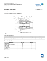
Mounting of connection plate, pos. 115
See the compressor spare parts manual.
Add grease to the two O-ring grooves, and mount the O-rings, pos. 107 and 117, in the grooves.
Place the plate on the valve/filter housing, pos. 300.
Insert the 8 bolts (M12), pos. 101.
Remember two bolts, pos. 119, from the inner side of the valve housing. Tighten to 98 Nm.
Grease the groove, and place the O-ring, pos. 116, in the groove. Also position the O-ring, pos. 102.
Erhardt Nielsen
Manager, Compressor Development
Engineering, Sabroe Products
Industrial Refrigeration Europe
Tel: +45 87 36 77 20
Mob: +45 29 22 77 20
E-mail: [email protected]
Internet: http://www.johnsoncontrols.dk/
115
107
117
300
106
101
116
102
/