English (GB)
2
English (GB) Service instructions
Original service instructions
CONTENTS
Page
1. Symbols used in this document
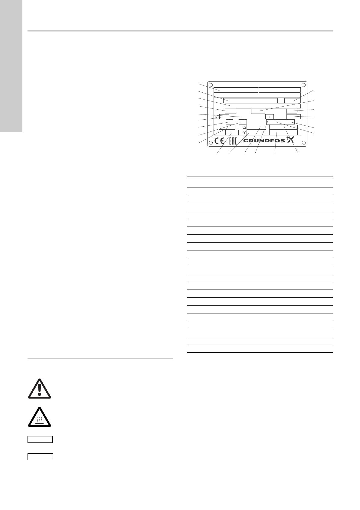
2. Identification
The nameplate is fitted to the top cover of the pump. Fix the extra
nameplate supplied with the pump at the installation site or keep
it in the cover of this booklet.
2.1 Nameplate
Fig. 1 Nameplate
1. Symbols used in this document
2
2. Identification
2
2.1 Nameplate
2
2.2 Type key, DWK
3
2.3 Type key, DPK
3
3. Tightening torques
4
4. Service tools
5
4.1 Standard tools
5
4.2 Torque tools
5
5. Dismantling
6
5.1 General information
6
5.2 Oil change
6
5.3 Removing impeller and pump housing
7
5.4 Removing shaft seals
8
5.5 Removing bearings
8
5.6 Removing cable
9
5.7 Removing stator
9
6. Assembly
10
6.1 Fitting stator
10
6.2 Fitting cable
10
6.3 Fitting bearings
12
6.4 Fitting shaft seals
12
6.5 Fitting impeller and pump housing
13
7. Fault finding
14
8. Components and material specification
15
8.1 DWK.O.6.50.075, DWK.O.6.50.15 and DWK.O.6.50.22
16
8.2 DWK.O.6.80.15, DWK.O.6.80.22, DWK.O.10.80.37
and DWK.O.10.100.37
17
8.3 DWK.O.13.80.55, DWK.O.13.100.55,
DWK.O.13.100.75, DWK.O.13.100.110,
DWK.O.13.100.150 and DWK.O.13.150.150
18
8.4 DWK.E.10.100.220, DWK.E.10.150.220,
DWK.E.10.150.300, DWK.E.10.200.300
19
8.5 DWK.E.10.150.370, DWK.E.10.150.450,
DWK.E.10.200.370, DWK.E.10.200.450,
DWK.E.10.150.550, DWK.E.10.200.550
20
8.6 DWK.E.10.200.750, DWK.E.10.200.900
21
8.7 DPK.10.50.075, DPK.10.50.15 and DPK.10.80.22
22
8.8 DPK.15.80.37, DPK.15.80.55, DPK.15.100.75,
DPK.20.100.110 and DPK.20.100.150
23
8.9 DPK.20.150.190 and DPK.20.150.220
24
8.10 DPK.V.65.80.15.2 and DPK.V.65.80.22.2
25
8.11 DPK.V.80.80.37.2
26
8.12 DPK.V.80.80.55.2 and DPK.V.80.80.75.2
27
8.13 DPK.V.65.80.15.4 and DPK.V.65.80.22.4
28
8.14 DPK.V.80.80.37.4, DPK.V.80.80.55.4 and
DPK.V.80.80.75.4
29
Warning
If these safety instructions are not observed, it may
result in personal injury.
Warning
The surface of the product may be so hot that it may
cause burns or personal injury.
If these safety instructions are not observed, it may
result in malfunction or damage to the equipment.
Notes or instructions that make the job easier and
ensure safe operation.
TM04 4093 1016
Pos. Description
1 Notified body
2 Type designation
3 Product number and serial number
4 Maximum head [m]
5 Enclosure class
6 Maximum installation depth [m]
7 Number of phases
8 Frequency [Hz]
9 Speed [min
-1
]
10 Weight
11 Rated voltage [V] Star
12 Rated voltage [V] Delta
13 Insulation class
14 Rated current [A] Star
15 Rated current [A] Delta
16 Motor input power P1 [kW]
17 Motor output power P2 [kW]
18 Power factor
19 Maximum liquid temperature [°C]
20 Maximum flow [l/s]
21 Production code (year/week)
1
2
3
4
5
6
7
8
9
10
11
12 13 14 15
16
17
18
19
20
21
DK-8850 Bjerringbro Denmark
Type
Model
Hmax Qmax Tmax. :
P.c.
m l/s c
P,3,QVXOFODVV&RVĭ
96883812
Made in China
Motor ~ Hz P1/P2 kW
n min
-1
Weight kg A
A
V
V


