
Euro Matic DOL 95 Breeder
Technical Manual


Technical Manual
Euro Matic DOL 95 Breeder
Program Version
The product described in this manual is computer-based, and most functions are implemented by
means of software. This manual corresponds to:
• Software version 4.6
It was released in March 2006.
Product and Documentation Changes
SKOV A/S reserve the right to change this document and the product described therein without notice.
SKOV A/S cannot guarantee that you will be informed about possible revisions of the product or the
manual. In case of doubt, please contact SKOV A/S.
Latest date of change appears from the back page.
NOTE
• All rights reserved. Reproduction of any part of this manual in any form whatsoever
without SKOV A/S’ express written permission is forbidden.
• All efforts have been made to assure the accuracy of the contents of this manual. However,
should any error be detected, SKOV A/S would greatly appreciate being informed.
• In spite of the above, SKOV A/S cannot assume responsibility for any error in this manual
or any consequences thereof.
• Copyright 2006 by SKOV A/S
IMPORTANT
• Read this manual thoroughly before installing and using DOL 95.
• SKOV A/S recommend the installation of an alarm system in connection with DOL 95. In
connection with control and inspection of the feeding system, interruptions, malfunctioning
or faulty settings may result in economic loss. It is very important to test the alarm system
and the connected alarm-related equipment at least once a week, preferably more
frequently.

Technical Manual
Euro Matic DOL 95 Breeder
1 INTRODUCTION 6
2 INSTALLATION 7
2.1 Mechanical Installation............................................................................7
2.1.1 Mounting the Unit on the Wall ........................................................................................ 7
2.2 Electrical Installation ...............................................................................8
2.2.1 Adjustment to Mains Voltage........................................................................................... 8
2.2.2 Wiring Diagram and Connection Diagrams................................................................... 8
2.2.3 Selection of Wiring Diagram.......................................................................................... 10
2.2.3.1 Destination Feeding .......................................................................................................... 10
2.2.3.2 Wiring Diagram 1 - Destination Feeding.......................................................................... 11
2.2.3.3 Traditional Feeding System .............................................................................................. 12
2.2.3.4 Wiring Diagram 2 - Not Destination Feeding DOL 95-1 ................................................. 13
2.2.3.5 Wiring Diagram 3 - Not Destination Feeding DOL 95-2 ................................................. 14
2.2.4 Wiring Diagrams Valid for all Systems.........................................................................15
2.2.4.1 Wiring Diagram 4 ............................................................................................................. 15
2.2.4.2 Wiring Diagram 5 ............................................................................................................. 16
2.2.4.3 Connection Diagram 1 ...................................................................................................... 17
2.2.4.4 Connection Diagram 2 ...................................................................................................... 17
2.2.4.5 Connection Diagram 3 ...................................................................................................... 17
2.2.4.6 Connection Diagram 4 ...................................................................................................... 18
2.2.4.7 Connection Diagram 5 ...................................................................................................... 19
2.2.4.8 Connection Diagram 6 ...................................................................................................... 20
2.2.4.9 Connection Diagram 7 ...................................................................................................... 21
2.2.4.10 Connection Diagram 8 ...................................................................................................... 21
2.2.4.11 Connection Diagram 9 ...................................................................................................... 21
2.2.4.12 Connection Diagram 10 .................................................................................................... 22
2.2.4.13 Connection Diagram 11 .................................................................................................... 22
2.2.4.14 Connection Diagram 12 .................................................................................................... 22
2.2.4.15 Connection Diagram 13 .................................................................................................... 23
2.2.4.16 Connection Diagram 14 .................................................................................................... 24
2.2.4.17 Connection Diagram 15 .................................................................................................... 25
2.2.4.18 Connection Diagram 16 .................................................................................................... 25
2.2.4.19 Connection Diagram 17 .................................................................................................... 26
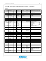
2.2.4.20 Description of Terminal Connections – Standard .............................................................27
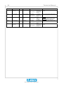
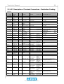
2.2.4.21 Description of Terminal Connections - Destination Feeding............................................29
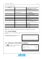
2.2.5 Basic Setting..................................................................................................................... 31
2.2.5.1 Setting Language, House Name, Date and Time .............................................................. 31
2.2.5.2 Setting Types of Birds and Number of Batches................................................................32
2.2.5.3 Setting Feeding System and Weigher ............................................................................... 33
2.2.5.4 Setting Light Control......................................................................................................... 33
2.2.5.5 Setting Water Registration and Control ............................................................................ 34
2.2.5.6 Setting Poultry Weighing.................................................................................................. 35
2.2.5.7 Setting Environmental Sensors ......................................................................................... 35
2.2.5.8 Setting Printer.................................................................................................................... 36

Technical Manual
Euro Matic DOL 95 Breeder
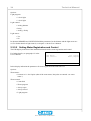
2.2.5.9 Setting Info Matic .............................................................................................................37
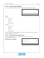
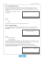
2.2.5.10 Setting Password ............................................................................................................... 38
2.2.5.11 Copy of Setup....................................................................................................................38
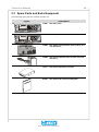
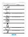
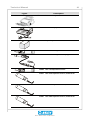
2.3 Spare Parts and Extra Equipment.........................................................39
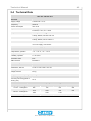
2.4 Technical Data........................................................................................43
3 SERVICE 44
3.1 Automatic/Manual Control.....................................................................46
3.2 Checking Inputs and Outputs ...............................................................46
3.3 Current Setting .......................................................................................47
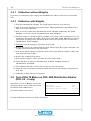
3.4 Calibration of DOL 99B Feed Weigher..................................................47
3.4.1 Calibration without Weights.......................................................................................... 48
3.4.2 Calibration with Weights ............................................................................................... 48
3.5 Test of DA 74 Motor on DOL 99B Distribution Shutter (DOL 95 - 2
only).........................................................................................................48
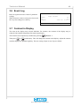
3.6 Event Log................................................................................................49
3.7 Contrast in Display.................................................................................49
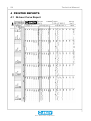
4 PRINTED REPORTS 50
4.1 24-hour Curve Report ............................................................................50
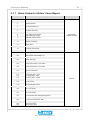
4.1.1 Alarm Codes for 24-hour Curve Report ....................................................................... 51
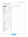
4.2 24-hour Report........................................................................................52
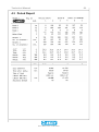
4.3 Period Report..........................................................................................53
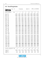
4.4 Feed Programme.................................................................................... 54
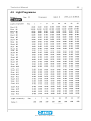
4.5 Light Programme....................................................................................55
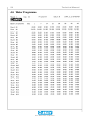
4.6 Water Programme ..................................................................................56
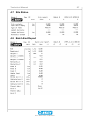
4.7 Silo Status...............................................................................................57
4.8 Batch End Report...................................................................................57

6 Technical Manual
Euro Matic DOL 95 Breeder
1 INTRODUCTION
This manual describes operation, setting and installation of the Euro Matic DOL 95-1 and DOL 95-2
production computers.
DOL 95 was especially designed for production control in houses with broilers, where DOL 95 can
control feed supply, lighting and water and record the feed and water consumption as well as the
number and weight of the birds. DOL 95 can give an alarm in case of error conditions and be
connected to a printer and a PC.
DOL 95-2 allows independent control of two houses, provided that a shared DOL 99B feed weigher is
used.
DOL 95 is a basic unit which allows the installation of accessories as required. The accessories
include a printer and data network module which allows printouts and PC connection respectively.
SKOV A/S congratulate you on your new
DOL 95 production computer

Technical Manual 7
Euro Matic DOL 95 Breeder
2 INSTALLATION
This section describes mechanical and electrical installation as well as basic setting of DOL 95.
2.1 Mechanical Installation
DOL 95 is delivered in a strong cardboard box, which also contains this manual, suspension
screws/plugs, possibly accessory modules and sensors and a folded user’s instruction. This instruction
can be mounted on the opening lid of DOL 95, so that it is always accessible.
Mechanical installation consists of fixing DOL 95 to the wall and mounting the accessory modules, if
any.
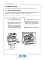
2.1.1 Mounting the Unit on the Wall
1) Open the lid that forms the lower part of
the front plate. Lift the lid lightly and tip
it forwards.
2) Remove the protective plate behind the
lid. The plate is fixed by means of 4
screws.
3) Hold DOL 95 up against the wall with
the display at eye height. Mark off the
two suspension holes through the holes
in DOL 95. 8 mm drill. Rubber disks
serve as seals under the screw heads.
Reserve sufficient space around DOL 95
for electric cables.
4) The operation panel can be loosened by
means of the 2 screws.
5) Accessory modules, if any, are mounted
on the relay panel. The modules are fixed
by means of plastics spacers and screws
and connected to the relay panel by
means of a wire set. See enclosed
instructions.
6) Slide the folded user’s instruction into
the lid.
Figure 1: Mounting on the wall

8 Technical Manual
Euro Matic DOL 95 Breeder
2.2 Electrical Installation
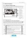
2.2.1 Adjustment to Mains Voltage
When DOL 95 is delivered it is set to 230V mains voltage. If the mains voltage of the country (or
area) is different, DOL 95 must be adjusted. This is done by means of the switch on the connection
circuit board - see Figure 2 below. DOL 95 can be set to 115/230V. If a DOL 99B feed weigher is
used, DOL 95 must be supplied with 230V.
1
5
8
6
7
2
3
4
230
1) Mains voltage switch,
115/230Vac.
2) Terminal block, low
voltage, house 1
3) Terminal block, low
voltage, house 2
4) Terminal block, low
voltage, joint
5) Terminal block, high
voltage, joint
6) Terminal block, high
voltage, house 1
7) Terminal block, high
voltage, house 2
8) Earth terminal and loop
terminals
Figure 2: Adjustment to mains voltage
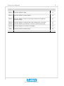
2.2.2 Wiring Diagram and Connection Diagrams
At the bottom of the wiring box there is room for a total of 26 PG13/16 unions. All cables must be led
through these unions and connected to the terminal blocks. The PG nuts are automatically retained.
Three unions in the left side should be reserved for connection of PC and printer module.
Generally, the wiring diagrams are only shown for house 1. House 2 is connected in the same way.
Diagram Subject Page
Figure 4 Wiring diagram 1: Feed valve, feed back, DOL 99B, feed demand sensor and level
switch sensor, empty. 11
Figure 6 Wiring diagram 2: DOL 99B, feed demand sensor, cross auger sensor. 13
Figure 7 Wiring diagram 3: DOL 99B, feed demand sensor, distribution shutter, cross auger
sensor. 14
Figure 8 Wiring diagram 4: Light dimmer, water meter, light sensor, poultry weigher,
environmental sensor, alarm. 15
Figure 9 Wiring diagram 5: Silo augers, cross augers, feeding system, light, water 16
Figure 10 Connection diagram 1: DOL 95, mains voltage 17
Figure 11 Connection diagram 2: DOL 95, silo augers 17
Figure 12 Connection diagram 3: DOL 95, switch and auxiliary contactor 17
Figure 13 Connection diagram 4: Destination feeding, DOL 95-1, DOL 95-2, DOL 99B poultry
weigher and container under DOL 99B. 18
Figure 14 Connection diagram 5: DOL 95-1, DOL 99B feed weigher, feed demand sensor 19
Figure 15 Connection diagram 6: DOL 95-2, DOL 99B feed weigher, feed demand sensor 20

Technical Manual 9
Euro Matic DOL 95 Breeder
Diagram Subject Page
Figure 16 Connection diagram 7: Motor on distribution shutter 21
Figure 17 Connection diagram 8: Alarm 21
Figure 18 Connection diagram 9: Environmental sensors 21
Figure 19 Connection diagram 10: Poultry weigher 22
Figure 20 Connection diagram 11: Dimmer, light sensor 22
Figure 21 Connection diagram 12: Sensor in cross auger container (is not applied by
destination feeding) 22
Figure 22 Connection diagram 13: Water meter 23
Figure 23 Connection diagram 14: Relays for light, water, feeding system, cross auger 24
Figure 24 Connection diagram 15: Pan feeding:, connection of sensor in the last pan 25
Figure 25 Connection diagram 16: Connection of tip weigher 25
Figure 26 Connection diagram 17: Destination feeding, feed valve, feedback. 26
Table 1 Terminal connections, standard system 28
Table 2 Terminal connections, destination feeding 30

10 Technical Manual
Euro Matic DOL 95 Breeder
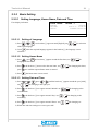
2.2.3 Selection of Wiring Diagram
The following pages are a guide to choosing the correct wiring diagrams.
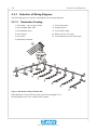
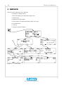
2.2.3.1 Destination Feeding
1) Feed augers - up to 4 types of feed
2) Feed weigher, DOL 99B
3) Feed demand sensor
4) Cross augers
5) Feed valve
6) Destination container
7) Cross auger motor
8) Feeding system
9) Level switch, empty
10) Safety stop for cross auger
11) Level indicator sensor in control pan
Figure 3: Destination feeding with DOL 99B
If this principle is not used in the system, proceed to paragraph 2.2.3.3.
Wiring diagram 4 and 5 are valid for all the systems.

Technical Manual 11
Euro Matic DOL 95 Breeder
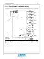
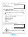
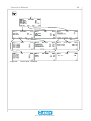
2.2.3.2 Wiring Diagram 1 - Destination Feeding
Control Contact boxes System House
DOL 95
Feed valves
DOL 99B
Feed demand
sensor and
level switch
sensor, empty
1 and 2
1 and 2
1 and 2
1 and 2
1 and 2
1 and 2
Shared
Shared
Figure 4: Wiring diagram 1: Feed valve, feed back, DOL 99B, feed demand sensor and level switch
sensor, empty.
NB Armoured installation cables (reinforced against rodent attack) must be used for all installations,
minimum 1 mm².

12 Technical Manual
Euro Matic DOL 95 Breeder
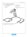
2.2.3.3 Traditional Feeding System
1) Feed augers - up to 4 types of feed
2) Feed weigher DOL 99B
3) Distribution shutter
4) Cross augers
5) Chain feeding system
6) Pan feeding system
7) Cross auger containers
8) Feed demand sensor in container (one for
each house)
Figure 5: Chain feeding system and pan feeding system with DOL 99B
Wiring diagram 4 and 5 are valid for all systems.

Technical Manual 13
Euro Matic DOL 95 Breeder
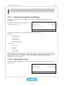
2.2.3.4 Wiring Diagram 2 - Not Destination Feeding DOL 95-1
Control Contact boxes System House
DOL 95
DOL 99B
Feed demand
sensor
Cross auger
sensor
1 and 2
Shared
Shared
Figure 6: Wiring diagram 2: DOL 99B, feed demand sensor, cross auger sensor.

14 Technical Manual
Euro Matic DOL 95 Breeder
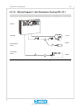
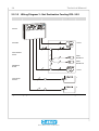
2.2.3.5 Wiring Diagram 3 - Not Destination Feeding DOL 95-2
Control Contact boxes System House
DOL 95
DOL 99B
Feed demand
sensor
Distribution
shutter
Cross auger
sensors
1 and 2
Feed
demand 1
Feed
demand 2
1 and 2
1
2
Figure 7: Wiring diagram 3: DOL 99B, feed demand sensor, distribution shutter, cross auger sensor.

Technical Manual 15
Euro Matic DOL 95 Breeder
2.2.4 Wiring Diagrams Valid for all Systems
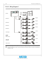
2.2.4.1 Wiring Diagram 4
Control Contact boxes System House
DOL 95
Light dimmer
Water meter
Light sensor
Poultry
weighers
Environmental
sensors
Alarm
1 and 2
1 and 2
1 and 2
1 and 2
1 and 2
1 and 2
1 and 2
1 and 2
Figure 8: Wiring diagram 4: Light dimmer, water meter, light sensor, poultry weigher, environmental
sensor, alarm.
NB Armoured installation cables (reinforced against rodent attack) must be used for all installations,
minimum 1 mm².

16 Technical Manual
Euro Matic DOL 95 Breeder
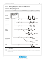
2.2.4.2 Wiring Diagram 5
Control Contact boxes System House
DOL 95
Silo feed 1
Silo feed 2
Silo feed 3
Silo feed 4
Cross auger
Feeding
system
(chain or pan)
Light, relay
controlled
Water control
Shared
Shared
Shared
Shared
1 and 2
1 and 2
1 and 2
1 and 2
Figure 9: Wiring diagram 5: Silo augers, cross augers, feeding system, light, water
NB Armoured installation cables (reinforced against rodent attack) must be used for all installations,
minimum 1 mm².

Technical Manual 17
Euro Matic DOL 95 Breeder
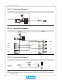
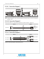
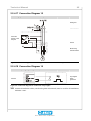
2.2.4.3 Connection Diagram 1
DOL 95
Mains voltage
Figure 10: Connection diagram 1: DOL 95, mains voltage
2.2.4.4 Connection Diagram 2
DOL 95 System
Silo 3
Silo 2
Silo 1
Silo 4
Silo 4
Silo 3
Silo 2
Silo 1
Figure 11: Connection diagram 2: DOL 95, silo augers
2.2.4.5 Connection Diagram 3
DOL 95
Switch and
contactor
Figure 12: Connection diagram 3: DOL 95, switch and auxiliary contactor
NB Armoured installation cables (reinforced against rodent attack) must be used for all installations,
minimum 1 mm².

18 Technical Manual
Euro Matic DOL 95 Breeder
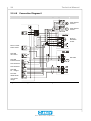
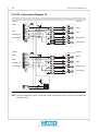
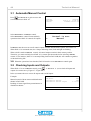
2.2.4.6 Connection Diagram 4
All DOL 95-1 and DOL 95-2 where destination feeding is applied
Feed demand
sensor
Level switch,
empty
DOL 99B
Figure 13: Connection diagram 4: Destination feeding, DOL 95-1, DOL 95-2, DOL 99B poultry weigher
and container under DOL 99B

Technical Manual 19
Euro Matic DOL 95 Breeder
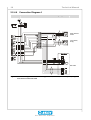
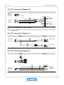
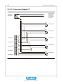
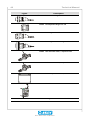
2.2.4.7 Connection Diagram 5
All DOL 95-1 where destination feeding is not applied
DOL 99B
drum motor
DOL 99B
inductive
sensor
Feed demand
sensor
DOL 99B
Ref.. +
weigher
+24V mains
voltage
Feed demand
sensor in DOL
99B
DOL 99B
Figure 14: Connection diagram 5: DOL 95-1, DOL 99B feed weigher, feed demand sensor
NB Armoured installation cables (reinforced against rodent attack) must be used for all installations,
minimum 1 mm².

20 Technical Manual
Euro Matic DOL 95 Breeder
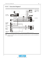
2.2.4.8 Connection Diagram 6
All DOL 95-2 where destination feeding is not applied
Motor on distri-
bution shutter
DOL 99B
drum motor
DOL 99B
inductive sensor
Feed demand 2
Feed demand 1
DOL 99B
ref. + weigher
Pot.meter
distrib.shutter
+24V mains
voltage
Feed demand
sensor 2
Feed demand
sensor 1
Motor on
distribution
shutter
DOL 99B
Figure 15: Connection diagram 6: DOL 95-2, DOL 99B feed weigher, feed demand sensor
Page is loading ...
Page is loading ...
Page is loading ...
Page is loading ...
Page is loading ...
Page is loading ...
Page is loading ...
Page is loading ...
Page is loading ...
Page is loading ...
Page is loading ...
Page is loading ...
Page is loading ...
Page is loading ...
Page is loading ...
Page is loading ...
Page is loading ...
Page is loading ...
Page is loading ...
Page is loading ...
Page is loading ...
Page is loading ...
Page is loading ...
Page is loading ...
Page is loading ...
Page is loading ...
Page is loading ...
Page is loading ...
Page is loading ...
Page is loading ...
Page is loading ...
Page is loading ...
Page is loading ...
Page is loading ...
Page is loading ...
Page is loading ...
Page is loading ...
Page is loading ...
Page is loading ...
Page is loading ...
-
 1
1
-
 2
2
-
 3
3
-
 4
4
-
 5
5
-
 6
6
-
 7
7
-
 8
8
-
 9
9
-
 10
10
-
 11
11
-
 12
12
-
 13
13
-
 14
14
-
 15
15
-
 16
16
-
 17
17
-
 18
18
-
 19
19
-
 20
20
-
 21
21
-
 22
22
-
 23
23
-
 24
24
-
 25
25
-
 26
26
-
 27
27
-
 28
28
-
 29
29
-
 30
30
-
 31
31
-
 32
32
-
 33
33
-
 34
34
-
 35
35
-
 36
36
-
 37
37
-
 38
38
-
 39
39
-
 40
40
-
 41
41
-
 42
42
-
 43
43
-
 44
44
-
 45
45
-
 46
46
-
 47
47
-
 48
48
-
 49
49
-
 50
50
-
 51
51
-
 52
52
-
 53
53
-
 54
54
-
 55
55
-
 56
56
-
 57
57
-
 58
58
-
 59
59
-
 60
60


Ask a question and I''ll find the answer in the document
Finding information in a document is now easier with AI
Related papers
-
Skov DOL 95 Broiler Owner's manual
-
-
-
-
-
-
-
-
-
Other documents
-
MCE HMC-PHC Hydro 42-02-1P00 H.4 User manual
-
-
-
 Chore-Time MF2495A MODEL C2® PLUS & MODEL G™ PLUS Installation and Operators Instruction Manual
-
-
-
-
-
-
