Page is loading ...

MOTION CONTROL ENGINEERING, INC.
11380 WHITE ROCK ROAD
RANCHO CORDOVA, CA 95742
TELEPHONE (916) 463-9200 FAX (916) 463-9201
IMC-MG MANUAL
January 2007
PART # 42-02-6202 REV B.3


42-02-6202 TABLE OF CONTENTS i
TABLE OF CONTENTS
IMPORTANT PRECAUTIONS AND NOTES .................................. xi
SECTION 1
PRODUCT DESCRIPTION
1.0 General Information ...............................................1-1
1.1 Car Controller Physical Layout.......................................1-3
1.2 Operation Overview ...............................................1-6
1.2.1 Car Operation Control (COC) Components .......................1-7
1.2.2 Car Operation Control (COC) Inputs and Outputs .................1-11
1.2.3 Car Communication Control (CCC) Components ..................1-13
1.2.4 Car Motion Control (CMC) Components .........................1-14
1.2.5 Car Motion Control (CMC) Inputs and Outputs ....................1-18
1.2.6 Car Power Control (CPC) Components .........................1-19
1.3 LS-QUAD-2 Landing System .......................................1-22
1.4 LS-QUIK Landing System .........................................1-24
1.5 Load Weighing System (Optional) ...................................1-26
SECTION 2
INSTALLATION
2.0 General Information ...............................................2-1
2.0.1 Site Selection ..............................................2-1
2.0.2 Environmental Considerations .................................2-1
2.0.3 Recommended Tools and Test Equipment ........................2-2
2.0.4 Wiring Prints...............................................2-2
2.1 Controller Installation ..............................................2-4
2.1.1 Controller Wiring Guidelines...................................2-4
2.2 General Wiring Guidelines ..........................................2-6
2.2.1 Ground Wiring .............................................2-6
2.2.2 Motor Generator Set Wiring ...................................2-7
2.2.3 DC Hoist Motor Wiring .......................................2-8
2.2.4 Tachometer Installation and Wiring .............................2-8
2.2.5 Brake Switch Installation and Wiring .............................2-9
2.3 Hoistway Control Equipment Installation ..............................2-10
2.3.1 Perforated Steel Tape for the LS-QUAD-2 .......................2-10
2.3.2 LS-QUIK-1 Landing System ..................................2-10
2.3.3 Hoistway Limit Switches .....................................2-10
2.3.4 Hoistway Terminal Strips and Traveling Cables ...................2-10

TABLE OF CONTENTS 42-02-6202ii
2.4 Car Control Equipment Installation...................................2-11
2.4.1 Installation of Landing System Control Box ......................2-11
2.4.2 Steel Tape on the LS-QUAD-2 Landing System Box ...............2-11
2.4.3 Magnetic Strips for the LS-QUAD-2 Landing System ...............2-12
2.4.4 Leveling/absolute Floor Encoding Vanes and Car Top Wheel Driven Encoder
for the LS-QUIK-1 .........................................2-13
2.4.5 TM Switch (If Used)........................................2-13
2.4.6 Door Operator Diode (If Used) ...............................2-13
2.4.7 Load Weigher ............................................. 2-13
2.4.8 Door Position Monitor Switch (If Used)..........................2-13
SECTION 3
START UP
3.0 General Information ...............................................3-1
3.1 Checking for Shorts to Ground ......................................3-1
3.2 Verifying Proper Voltages ..........................................3-2
3.2.1 Before Applying Power.......................................3-2
3.2.2 Applying Power ............................................3-3
3.3 Installing and Using the CRT Terminal/emulator .........................3-4
3.3.1 Accessing the Menu Screens ..................................3-4
3.3.2 CRT Menus ...............................................3-4
3.4 Verifying the Initial Parameter Values .................................3-8
3.5 Verifying Relay Operation , Voltage and Polarity ........................ 3-11
3.6 Moving the Car on Inspection Operation ..............................3-15
3.7 Preparation for Final Adjustment ....................................3-17
SECTION 4
FINAL ADJUSTMENT
4.0 General Information ...............................................4-1
4.1 Learning the Building Floor Heights ...................................4-1
4.1.1 Floor Height Learn Procedure .................................4-1
4.2 Verifying Absolute Floor Numbers ....................................4-5
4.3 Running on Automatic Operation .....................................4-7
4.3.1 Reaching Contract Speed ...................................4-10
4.3.2 Shaping the Velocity Profile ..................................4-14
4.3.3 Adjusting Leveling and Final Stop .............................4-15
4.4 Calibration and Verification of Safety Functions .........................4-19
4.4.1 Tach Failure ..............................................4-19

42-02-6202 TABLE OF CONTENTS iii
4.4.2 Inspection/leveling Overspeed ................................4-20
4.4.3 Contract Overspeed ........................................4-20
4.4.4 Tach Error ...............................................4-20
4.4.5 Armature Overcurrent (Overload Protection) .....................4-21
4.4.6 Controlling Car Motion at Initial Start ...........................4-22
4.4.7 Setting the Pre-torque Parameters.............................4-23
4.4.8 Adjustment of Initial Start Parameters ..........................4-24
4.4.9 Load Weigher Adjustment for Dispatching .......................4-26
4.5 Closed Loop Motor Field Control ....................................4-32
4.6 Normal Terminal Limit Switch Learn Operation .........................4-33
4.7 Final Elevator Inspection ..........................................4-35
4.7.1 Contract Speed Buffer Tests .................................4-35
4.7.2 Governor Tests............................................4-37
4.7.3 Inspection/leveling 150 FPM Overspeed Test .....................4-38
4.7.4 Tach Error ...............................................4-38
4.7.5 Normal Terminal Limit Switch Test .............................4-38
SECTION 5
HUMAN INTERFACE
5.0 General Information ...............................................5-1
5.1 Enhanced Onboard Diagnostics (EOD) Overview ........................5-1
5.1.1 Description of EOD Lights and Switches .........................5-1
5.2 Normal Mode (EOD) ..............................................5-4
5.2.1 Alphanumeric Display (Default Displays) .........................5-4
5.2.2 Diagnostic Indicators ........................................5-6
5.2.3 Adjustment of the Elevator Timers ..............................5-7
5.2.4 Setting the Real Time Clock...................................5-9
5.2.5 Alphanumeric Display - Viewing the MP /MP2 Internal Flags / Inputs . . . 5-10
5.3 System Mode (EOD) .............................................5-11
5.3.1 Programming the Communication Ports.........................5-12
5.3.2 Viewing and Changing the Security Codes.......................5-14
5.3.3 Hoistway Learn Operation ...................................5-16
5.3.4 Setting MSK: Master Software Key.............................5-16
5.3.5 Setting the Software Options - Adjustable Control Variables .........5-17
5.3.6 Load Weigher Learn Operation ...............................5-19
5.3.7 Setting and Resetting the Passcode Option (Not on All Controllers) ....5-19
5.4 Diagnostic Mode (EOD) ...........................................5-21
5.4.1 Viewing the MC-MP Computer Variable Flags ....................5-21
5.4.2 Viewing the IMC-DDP Computer Variable Flags...................5-26
5.4.3 Viewing and Entering Calls...................................5-29
5.5 IMC-DIO Onboard Diagnostics ......................................5-30
5.5.1 Description of IMC-DIO Indicators and Switches ..................5-30
5.5.2 Startup Operation..........................................5-30
5.5.3 IMC-DIO Learn Operation ....................................5-31
5.5.4 IMC-DIO Normal Operation ..................................5-31

TABLE OF CONTENTS 42-02-6202iv
SECTION 6
TROUBLESHOOTING
6.0 General Information ...............................................6-1
6.1 Car Operation, Drive and Safety Flags ................................6-2
6.2 Pattern Generator Flags ...........................................6-8
6.3 Computer Swing Panel Indicators and Alphanumeric Display ..............6-14
6.4 Special Event Calendar Entries - F7 Screen ...........................6-26
6.5 Troubleshooting Car Operation Control (COC) ......................... 6-33
6.5.1 Door Logic ...............................................6-33
6.5.2 Call Logic - Normal Operation ................................6-38
6.5.3 Troubleshooting the Call Circuits ..............................6-40
6.5.4 Troubleshooting the Call Indicators ............................ 6-41
6.6 PC Board Quick References .......................................6-41
6.7 Using the MLT Data Trap..........................................6-54
APPENDICES
Appendix A Disassembling the Computer Swing Panel ........................A-1
Appendix B Changing PC Boards, EPROMs and Microcontrollers ...............A-2
B.1 Replacing the MC-MP-1ES / MC-MP2 Board or EPROM.............A-2
B.2 Replacing the IMC-DDP-C Board or EPROM......................A-3
B.3 Replacing the IMC-DIO Board or MicroControllers..................A-4
B.4 Replacing the IMC-DAS Board.................................A-6
B.5 EPROM Installation or Replacement on MC-NC and MC-NIO Boards . . . A-6
Appendix C Elevator Security Information and Operation ......................A-9
Appendix D Instructions for the Inspection of Quadrature Position Pulser .........A-11
D.1 Instructions for the LS-QUAD-2 ...............................A-11
D.2 Instructions for the LS-QUIK-1 ................................A-13
Appendix E Nomenclature .............................................A-14
Appendix F Replacement of IMC Drive Components ........................A-16
Appendix G K-TECH Load Weigher Calibration .............................A-25
G.1 Calibrating the K-TECH LW-KK2 Load Weigher ..................A-25
G.1.1 Calibrating the Sensor Adjust Trimpot..................A-26
G.1.2 Calibrating the Zero Adjust Trimpot (Empty Car)..........A-28
G.1.3 Calibration of the Gain Adjust Trimpot (Full Load).........A-28
G.2 Troubleshooting the K-TECH Load Weigher .....................A-30

42-02-6202 TABLE OF CONTENTS v
Appendix H MCE Load Weigher Installation and Adjustment ...................A-32
H.0 General Information ........................................A-32
H.1 Sensor Installation Methods ..................................A-32
H.1.1 Installation Method #1 Overview (Preferred Method) .......A-33
H.1.2 Method #1 Installation Instructions ....................A-35
Appendix I Option SmartLINK for Car Operating Panel ......................A-39
Appendix J Closed Loop Motor Field Adjusting Instructions ...................A-57
Appendix K Flex-Talk Option ...........................................A-58
Appendix L CRT Terminal and Terminal Emulator Setup .....................A-61
L.1 General ..................................................A-61
L.1.1 Controller Com Port Settings.........................A-61
L.2 Esprit 250C Terminal Emulator Setup ..........................A-63
L.2.1 Controller Com Port Setting (Esprit 250C) ...............A-63
L.2.2 Esprit 250C Terminal Emulator Connections .............A-63
L.2.3 Esprit 250C Terminal Emulator Setup..................A-64
L.2.4 Parallel Printer Setup (Esprit 250C) ....................A-68
L.2.5 Printing Screens with the Esprit 250C Terminal ..........A-70
L.3 ADDS 260LF Terminal Emulator Setup .........................A-71
L.3.1 Controller Com Port Settings (ADDS 260LF).............A-71
L.3.2 ADDS 260LF Terminal Emulator Connections ............A-71
L.3.3 ADDS 260LF Terminal Emulator Setup.................A-72
L.3.5 Troubleshooting ..................................A-79
L.4 Link MC5 Monochrome Terminal Setup .........................A-80
L.4.1 Controller Com Port Setting (Link MC5) ................A-80
L.4.2 Link MC5 Monochrome Terminal Connections ...........A-80
L.4.3 Link MC5 Terminal Setup ...........................A-81
L.5 Wyse WY-325ES Color Terminal Setup.........................A-84
L.5.1 Controller Com Port Setting (Wyse WY-325ES) ..........A-84
L.5.2 Wyse WY-325ES Color Terminal Connections ...........A-84
L.5.3 Wyse WY-325ES Color Terminal Setup ................A-84
L.5.4 Printer Setup.....................................A-88
L.5.5 Printing Screens ..................................A-88
L.6 Wyse WY-370 Color Terminal Setup ...........................A-89
L.6.1 Controller Com Port Setting (Wyse WY-370) ............A-89
L.6.2 Wyse WY-370 Color Terminal Connections .............A-89
L.6.3 Wyse WY-370 Color Terminal Setup...................A-90

TABLE OF CONTENTS 42-02-6202vi
REFERENCE SECTION
TABLES
Table R.1 Pattern Parameter Adjustments ................................R-1
Table R.2 Recommended Speed Pattern Parameters .......................R-3
Table R.3 Profile Parameter Adjustments.................................R-4
Table R.4 Motor Parameter Adjustments .................................R-6
Table R.5 Gain Parameter Adjustments ..................................R-8
Table R.6 Option/Calibration Parameter Adjustments.......................R-10
Table R.7 Auxiliary Drive Parameter Adjustment ..........................R-12
Table R.8 Dynamic Parameter Screen ..................................R-14
Table R.9 Digital Drive Indicators and Switches ...........................R-15
Table R.10 Software Test Points on the IMC-DAS ..........................R-16
Table R.11 Software Test Point Assignment ..............................R-17
Table R.12 Notch Filter Adjustment .....................................R-27
FIGURES
Figure R.1 CRT Main Menu...........................................R-18
Figure R.2 CRT Main Menu (Simplex) ...................................R-18
Figure R.3 Digital Drive Parameters Menu (Shift F2 - Simplex, F1 - Local) .......R-19
Figure R.4 Pattern Parameters Screen (Shift F2-1 - Simplex, F1-1 - Local) .......R-19
Figure R.5 Profile Parameters Screen (Shift F2-2 - Simplex, F1-2 - Local) .......R-20
Figure R.6 Motor Parameters Screen (Shift F2-3 - Simplex, F1-3 - Local) ........R-20
Figure R.7 Gain Parameters Screen (Shift F2-4 - Simplex, F1-4 - Local).........R-21
Figure R.8 Option/Calibration Parameters Screen (Shift F2-5 - Simplex,
F1-5 - Local)..............................................R-21
Figure R.9 Auxiliary Drive Parameters Screen (Shift F2-6 - Simplex,
F1-6 - Local)..............................................R-22
Figure R.10 Terminal Limit Switches Screen (Shift F2-7 - Simplex, F1-7 - Local) . . . R-22
Figure R.11 Floor Heights Screen (Shift F2-8 - Simplex, F1-8 - Local) ...........R-23
Figure R.12 Dynamic Parameters Warning Screen (Shift F2-9 - Simplex,
F1-9 - Local)..............................................R-24
Figure R.13 Dynamic Adjustment Parameters Screen (Shift F2-9 - Simplex,
F1-9 - Local)..............................................R-24
Figure R.14 Velocity vs Time Graphic Display (Shift F3 - Simplex, F2 - Local) .....R-25
Figure R.15 Graphic Display of Elevator, F3 Screen .........................R-25
Figure R.16 Computer Parameters Screen, F6 (Simplex Only) .................R-26

42-02-6202 TABLE OF CONTENTS vii
TABLES
Table 4.1 Absolute Floor Indicator Listing.................................4-6
Table 5.1 Timers and their Ranges .....................................5-8
Table 5.2 Clock Parameters and Ranges .................................5-9
Table 5.3 Communication Port Menu ...................................5-13
Table 5.4 Media Menu ..............................................5-13
Table 5.5 Device Menu..............................................5-13
Table 5.6 Changing the Floor Security Status and Security Code .............5-15
Table 5.7 Software Options ..........................................5-17
Table 5.8 MC-MP Computer Variable Flags..............................5-23
Table 5.9 MC-MP Diagnostic Mode Addresses and Computer Variable Flags ....5-24
Table 5.10 MC-MP Diagnostic Mode Rear Door Addresses and
Computer Variable Flags ....................................5-25
Table 5.11 IMC-DDP Computer Variable Flags ............................5-27
Table 5.12 IMC-DDP Diagnostic Mode Addresses and Computer Variable Flags . . 5-28
Table 6.1 Car Operation Flags - F3 Screen ...............................6-3
Table 6.2 Drive Operation Flags - F3 Screen..............................6-3
Table 6.3 Drive Status Flags - F3 Screen.................................6-4
Table 6.4 Drive Current and Voltage - F3 Screen...........................6-4
Table 6.5 Drive Fault Flags - F3 Screen..................................6-5
Table 6.6 Safety Processor Flags - F3 Screen.............................6-7
Table 6.7 Pattern Generator Operation - F3 Screen .........................6-9
Table 6.8 Pattern Generator Status - F3 Screen ..........................6-10
Table 6.9 Pattern Generator I/O Signals- F3 Screen .......................6-10
Table 6.10 Pattern Generator Faults - F3 Screen ...........................6-11
Table 6.11 Position - F3 Screen........................................6-13
Table 6.12 Velocity - F3 Screen ........................................6-13
Table 6.13 MC-MP-1ES Status and Error Messages ........................6-15
Table 6.14 IMC-DDP Status and Error Messages ..........................6-17
Table 6.15 Status and Error Messages ..................................6-18
Table 6.16 Special Event Descriptions ( F7 - 1 - S) screen ...................6-27
Table 6.17 Call Board Troubleshooting ..................................6-40
Table 6.18 Call Indicator Troubleshooting ................................6-41
Table I.1 Principle Characteristics.....................................A-39
Table I.2 Indicator Specification ......................................A-47
Table I.3 Miniature Bayonet Bulbs.....................................A-47
Table I.4 Single Contact Bayonet Bulbs ................................A-48
Table I.5 Double Contact Bayonet Bulbs ................................A-48
Table I.6 Screw Base Bulbs .........................................A-48
Table I.7 PSB5 Bulbs ..............................................A-48
Table I.8 Existing Traveler-Communication Cable Specification ..............A-48
Table I.9 New Traveler-Communication Cable Specification.................A-49
Table I.10 Key Diagnostic Memory Addresses ............................A-56
Table L.1 Communication Port Menu ...................................A-62
Table L.2 COM Port Media Selections ..................................A-62
Table L.3 COM Port Device Selections .................................A-62

TABLE OF CONTENTS 42-02-6202viii
FIGURES
Figure 1.1 Car Controller Functional Layout ...............................1-2
Figure 1.2 IMC-MG Controller Cabinet Layout..............................1-3
Figure 1.3 IMC-MG Computer Swing Panel ...............................1-4
Figure 1.4 Main Processor Board (MC-MP-1ES)............................1-5
Figure 1.5 Communication Processor Board (MC-CPA-1SL) ..................1-5
Figure 1.6 Digital Drive Processor Board (IMC-DDP-X).......................1-6
Figure 1.7 Communication Interface Board (MC-MRS) .......................1-6
Figure 1.8 Main Relay Board (HC-RB4) ..................................1-7
Figure 1.9 Power Input/Output Board (HC-PI/O) ............................1-8
Figure 1.10 Position Indicator Expander Board(HC-PI/X) ......................1-8
Figure 1.11 Call Input/Output Board (HC-CI/O) ..............................1-9
Figure 1.12 Input/Output Expander Board (HC-IOX) ..........................1-9
Figure 1.13 Digital Drive Unit (IMC-Gxx) ..................................1-10
Figure 1.14 Mother Board (IMC-MB)..................................... 1-11
Figure 1.15 Generator Power Adaptor Board (IMC-GPA-IX) ...................1-12
Figure 1.16 Data Acquisition System Board Layout (IMC-DAS) ................1-13
Figure 1.17 Digital Input/Output Board Layout (IMC-DIO) ..................... 1-14
Figure 1.18 Relay Interface Board (IMC-RI) ...............................1-15
Figure 1.19 Power Relay Interface Board (IMC-PRIX) .......................1-15
Figure 1.20 Power Relay Interface Board - High Power (IMC-PRIH).............1-16
Figure 1.21 Car Top Control Box (LS-QUAD-2) ............................1-18
Figure 2.1 Position Pulser Shielded Cable Wiring...........................2-5
Figure 2.2 Controller Board Layout - Typical Example........................2-6
Figure 2.3 Tachometer Installation ......................................2-9
Figure 2.4 Typical Tachometer Installation ...............................2-10
Figure 2.5 Encoder Installation ........................................2-11
Figure 3.1 IMC-MG Controller Cabinet Layout..............................3-1
Figure 3.2 Connecting MC-MRS to CRT ..................................3-3
Figure 3.3 CRT Main Menu ............................................3-4
Figure 3.4 Digital Drive Parameters Menu.................................3-5
Figure 3.5 Pattern Parameter Screen ....................................3-6
Figure 3.6 Dynamic Parameter Screen ...................................3-6
Figure 3.7 BIP Trimpot on the IMC-DAS Board.............................3-9
Figure 3.8 HC-RB4 BB Timer .........................................3-10
Figure 3.9 Signal at the MFI Test Point on the IMC-DAS Board ...............3-13
Figure 4.1 IMC-RI Board Cut-Out .......................................4-1
Figure 4.2 Diagnostic Address for 28, 29, 2E on Diagnostic
Indicators on Front of Computer Swing Panel .....................4-2
Figure 4.3 Digital Drive Diagnostic Address 10 .............................4-4
Figure 4.4 LS-QUAD-2 Detail ..........................................4-7
Figure 4.5 Velocity vs. Time Graph - F2 Screen ...........................4-10
Figure 4.6 Reduced Gains at Contract Speed .............................4-11
Figure 4.7 Releveling Gains ..........................................4-16
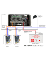
Figure 4.8 Nyload Weighing System of K-Tech International .................4-21
Figure 4.9 Brake Timing Diagram ...................................... 4-23
Figure 5.1 Computer Swing Panel Front View..............................5-1
Figure 5.2 Vertical Status Indicators .....................................5-4
Figure 5.3 Diagnostic Indicators ........................................5-4
Figure 5.4 Address and Function Switches ................................5-5
Figure 5.5 Computer Swing Panel Top View...............................5-5
Figure 5.6 Computer Swing Panel Back Plate..............................5-6
Figure 5.7 Diagnostic Mode (EOD) ..................................... 5-11

42-02-6202 TABLE OF CONTENTS ix
Figure 5.8 Viewing the Flags at Address 20H .............................5-12
Figure 5.9 Viewing and Entering Hall & Car Calls via the EOD ................5-13
Figure 5.10 Connecting MC-MRS to CRT .................................5-16
Figure 5.11 IMC-DIO Board Layout......................................5-19
Figure 5.12 Flag Address on MC-MP-1ES Board ...........................5-31
Figure 5.13 Rear Door Flag Address on MC-MP-1ES Board...................5-32
Figure 5.14 Flag Address on IMC-DDP-X Board ............................5-33
Figure 6.1 Graphic Display of Elevator Screen, F3 ..........................6-2
Figure 6.2 Velocity Vs Time Graphic Display, F2 Screen ......................6-8
Figure 6.3 Graphic Display of Elevator F3 Screen ..........................6-9
Figure 6.4 Computer Swing Panel, Front View ............................6-14
Figure 6.5 Special Event Calendar (F7) screen ..............................6-26
Figure 6.6 HC-PI/O Power Input/Output Board Quick Reference ..............6-35
Figure 6.7 HC-RB4 Main Relay Board Detail .............................6-36
Figure 6.8 Door Sequence of Operation Flowchart .........................6-37
Figure 6.9 HC-CI/O Call Input/Output Board Quick Reference ................6-39
Figure 6.10 Standard Board Layout ......................................6-42
Figure 6.11 MC-MP-1ES Main Processor Board Quick Reference ..............6-43
Figure 6.12 MC-MP2 Main Processor Board Quick Reference .................6-44
Figure 6.13 MC-CPA Communication Processor Board Quick Reference.........6-45
Figure 6.14 MC-MRS / ARS Communication Interface Board Quick Reference ....6-46
Figure 6.15 IMC-DDP-x Digital Drive Processor Board Quick Reference .........6-47
Figure 6.16 IMC-DAS Data Acquisition System Board Quick Reference..........6-49
Figure 6.17 IMC-DIO Digital Input/Output Board Quick Reference ..............6-51
Figure 6.18 IMC-GPA General Power Adapter Board Quick Reference ..........6-52
Figure 6.19 IMC-PRI-ENH Power Interface Board Quick Reference .............6-53
Figure A.1 Computer Swing Panel With Boards (Top View) ...................A-1
Figure A.2 Computer Swing Panel Without Boards (Top View) .................A-1
Figure A.3 Computer Swing Panel Boards (Snapped Together) ................A-1
Figure A.4 Computer Swing Panel Boards (Unsnapped) ......................A-1
Figure C.1 EPROM Location on the MC-NIO Board..........................A-7
Figure C.2 EPROM Location on the MC-NC Board ..........................A-8
Figure D.1 LS-QUAD Enclosure (Top View)...............................A-11
Figure D.2 Attaching SB1 to LS-QUAD2 Backplate.......................A-11
Figure D.3 Signal Comparison of DP1 and DP2............................A-12
Figure F.1 IMC-GPA-I Removal........................................A-16
Figure F.2 IGBT Removal ............................................A-17
Figure F.3 Spreading ................................................A-18
Figure F.4 Inserting IGBT Into Screw Terminal ............................A-18
Figure F.5 Snubber Capacitor Installation ................................A-18
Figure F.6 Motor Field Circuit .........................................A-20
Figure F.7 Generator Shunt Field Circuit .................................A-20
Figure F.8 Brake Circuit..............................................A-20
Figure F.9 Part of IMC-G233 Drive Unit (T1 and T2 Removal and Installation) ....A-21
Figure F.10 Part of IMC-G233 Drive Unit (DBB, DBG and D8 Removal and
Installation)...............................................A-22
Figure F.11 Part of IMC-G233 Drive Unit (Motor Field Diode/SCR Bridge Removal
and Installation) ...........................................A-23
Figure F.12 Part of IMC-G233 Drive Unit (Generator Shunt Field IGBT Removal
and Installation) ...........................................A-24
Figure G.1 Nyload (Blue) Control Box: LW3200-MC2 .......................A-25
Figure G.2 Dual Sensor Single Averaged Analog Output.....................A-26
Figure G.3 K-Tech Amplifier Board Test and Adjustment Points ...............A-27
Figure G.4 HC-LWB Buffer Board ...................................A-29

TABLE OF CONTENTS 42-02-6202x
Figure H.1 MCE Load Weigher ........................................A-32
Figure H.2 Center of Gravity vs Center of Floor............................A-33
Figure H.3 Sensing the Edges of the Floor (compensation for floor sag) .........A-33
Figure H.4 Target Bracket and Sensor mounted on Support Assembly and
Car frame................................................A-34
Figure H.5 Alternate Mounting Location for Sensor and Target ................A-34
Figure H.6 Typical Support Assembly for Target Bracket.....................A-35
Figure H.7 Wiring the HC-LWIP board ...................................A-36
Figure I.1 Typical IMC-SCR System....................................A-40
Figure I.2 MC-NC Neuron Controller Board ..............................A-41
Figure I.3 MC-NIO Neuron Input/Output Board ...........................A-41
Figure I.4 MC-NIO-X Neuron Input/Output Extender Board ..................A-42
Figure I.5 Mounting Plate Dimensions for Mounting the MC-NIO and
MC-NIO-X boards..........................................A-43
Figure I.6 Mounting Option 1: Boards Stacked ............................A-44
Figure I.7 Mounting Option 2: Boards Placed End to End ....................A-45
Figure I.8 Mounting Option 3: Boards Placed Side By Side ..................A-46
Figure I.9 MC-NC Board Quick Reference ...............................A-51
Figure I.10 MC-NIO Board Quick Reference ..............................A-53
Figure I.11 Diagnostic Switch Settings for Address 3000 HEX .................A-56
Figure K.1 TPI-FT Flex-Talk Board .....................................A-58
Figure K.2 Diagnostic Table...........................................A-59
Figure K.3 Speaker Dimensions .......................................A-60

42-02-6202 PRECAUTIONS & NOTES • xi
IMPORTANT PRECAUTIONS & NOTES
We strongly recommend that you read this manual carefully before proceeding with installation.
Throughout this manual you will see icons followed by a WARNING, CAUTION or NOTE. These
icons denote the following:
WARNING: Operating procedures and practices which, if not done correctly,
may result in personal injury or substantial damage to equipment.
CAUTION: Operating procedures and practices which, if not observed, may
result in some damage to equipment.
NOTE: Procedures, practices or information which are intended to be
immediately helpful and informative.
The following general rules and safety precautions must be observed for safe and reliable
operation of your system.
The controller may be shipped without the final running program. However, you
may install the unit, hookup and run the elevator on Inspection operation. Call
MCE approximately one week before you are ready to turn the elevator over to
full automatic operation so the running program can be shipped to you. If you
need to change a program chip on a computer board make sure you read the
instructions and know exactly how to install the new chip. Plugging these
devices in backwards may damage the chip.
Elevator control products must be installed by experienced field personnel. This
manual does not address code requirements. The field personnel must know
all the rules and regulations pertaining to the safe installation and operation of
elevators.
This equipment is an O.E.M. product designed and built to comply with ANSI
A17.1, National Electrical Code, CAN/CSA-B44.1-M91/ASME-A17.5-1991 and
must be installed by a qualified contractor. It is the responsibility of the
contractor to make sure that the final installation complies with all local codes
and is installed in a safe manner.
The 3 phase AC power supply to this equipment must originate from a fused
disconnect switch or circuit breaker which is sized in conformance with all
applicable national, state and local electrical codes, in order to provide the
necessary overload protection for the drive unit and motor. Incorrect motor
branch circuit protection will void warranty and may create a hazardous
condition.
Proper grounding is vitally important to the safe and successful operation of
your system. Bring your ground wire to the system subplate. You must choose
the proper conductor size and minimize the resistance to ground by using the
shortest possible routing. See National Electrical Code Article 250-95, or the
applicable local electrical code.

• PRECAUTIONS & NOTES 42-02-6202xii
Before applying power to the controller, physically check all the power resistors
and other components located in the resistor cabinet and inside the controller.
Components loosened during shipment may cause damage.
You must not connect the output triacs directly to a hot bus (2, 3 or 4 bus).
This can damage the triacs. PIs, direction arrows, and terminals 40 & 42 are
examples of outputs that can be damaged this way. Note: miswiring terminal
39 into 40 can damage the fire warning indicator triac.
The HC-PI/O and HC-CI/O boards are equipped with quick disconnect
terminals. During the initial installation, you may want to remove the terminal
connector, hook up the field wires, test for no shorts to ground (1 bus) and to
2, 3 and 4 terminals before plugging these terminals back into the PC boards.
ENVIRONMENTAL CONSIDERATIONS: Keep the machine room clean. Controllers are
generally in NEMA 1 enclosures. Do not install the controller in a dusty area. Do not install the
controller in a carpeted area. Keep room temperature between 32
to 104 F (0 to 40 C).
Avoid condensation on the equipment. Do not install the controller in a hazardous location or
where excessive amounts of vapors or chemical fumes may be present. Make sure power line
fluctuations are within +
10%.
CONTROLLER OR GROUP ENCLOSURES WITH AIR CONDITIONING
If your controller or group enclosure is equipped with an air conditioning unit, observe the
following precautions (failure to do so can result in water condensation inside the enclosure):
• Ensure the integrity of the NEMA 12 or 4 enclosure is maintained by using sealed
knockouts and by sealing any holes created during installation.
• Do not run the air conditioner unit when the doors are open.
• To avoid damaging the compressor, if the air conditioner is turned off while it is running,
wait at least five minutes before turning power on again.
• Observe the manufacture’s recommended maintenance and optimum thermostat setting
of 75
o
F (see Operator’s Manual).
• Ensure the air conditioner unit’s drain hose remains open.

42-02-6202 PRECAUTIONS & NOTES • xiii
LIMITED WARRANTY
Motion Control Engineering (manufacturer) warrants its products for a period of 15 months from the date of
shipment from its factory, to be free from defects in workmanship and materials. Any defect appearing more
than 15 months from the date of shipment from the factory shall be deemed to be due to ordinary wear and tear.
Manufacturer, however, assumes no risk or liability for results of the use of the products purchased from it,
including, but without limiting the generality of the forgoing: (1) The use in combination with any electrical or
electronic components, circuits, systems, assemblies or any other material or equipment (2) Unsuitability of this
product for use in any circuit, assembly or environment. Purchaser's rights under this warranty shall consist
solely of requiring manufacturer to repair, or in manufacturer's sole discretion, replace free of charge, F.O.B.
factory, any defective items received at said factory within the said 15 months and determined by manufacturer
to be defective. The giving of or failure to give any advice or recommendation by manufacturer shall not
constitute any warranty by or impose any liability upon manufacturer. This warranty constitutes the sole and
exclusive remedy of the purchaser and the exclusive liability of the manufacturer, AND IN LIEU OF ANY AND
ALL OTHER WARRANTIES, EXPRESSED, IMPLIED, OR STATUTORY AS TO MERCHANTABILITY,
FITNESS, FOR PURPOSE SOLD, DESCRIPTION, QUALITY PRODUCTIVENESS OR ANY OTHER MATTER.
In no event shall manufacturer be liable for special or consequential damages or for delay in performance of this
warranty.
Products that are not manufactured by MCE (such as drives, CRTs, modems, printers, etc.) are not covered
under the above warranty terms. MCE, however, extends the same warranty terms that the original
manufacturer of such equipment provides with their product (refer to the warranty terms for such products in their
respective manual).


42-02-6202 PRODUCT DESCRIPTION • 1-1
SECTION 1
PRODUCT DESCRIPTION
1.0 GENERAL INFORMATION
The IMC-MG traction controller consists of four major pieces of equipment: a car controller, car
top selector (landing system), diagnostic tools and peripherals and a group dispatcher. IMC-MG
maintains complete regulation under varying loads for exceptional performance with DC motor
generators. All controllers have the features listed below:
PRODUCT FEATURES
Car Speed Up to 2500 fpm
Jerk 15 ft/sec
3
(4.572 m/sec
3
), maximum
7 ft/sec
3
(2.134 m/sec
3
), nominal
1 ft/sec
3
(.305 m/sec
3
), minimum
Acceleration 10 ft/sec
2
(3.048 m/sec
2
), maximum
4 ft/sec
2
(1.219 m/sec
2
), nominal
1 ft/sec
2
(.305 m/sec
2
), minimum
Number of
Stops
63 (currently available)
Number of
Cars in Group
12 (maximum)
Floor Leveling
Accuracy
± 1/4 inch (6.35mm), guaranteed
± 1/8 inch (3.175mm), typical
Minimum
Floor-to-Floor
Time
4.3 seconds for 12-foot (3.66mm)
floor heights if rotating equipment is
capable of delivering the necessary
torque
Environment
Limits
32 -104°F (0 - 40°C) ambient
12,000 ft altitude
95% humidity

• PRODUCT DESCRIPTION 42-02-62021-2
INPUT/OUTPUT
BOARDS
HC-CI/O
HC-1OX
HC-PIX
HC-140
MC-NC
WPD 1693 R2
The IMC-MG traction controller consists of a Car Controller, a Cartop Selector (landing system),
diagnostic tools and peripherals (Swing Panel, CRT terminal or PC) and if the controller is part
of a group, a Group Supervisor. The computer peripherals and Group Supervisor controller are
covered in detail in separate manuals.
IMC-MG controller diagnostics and adjustments are performed through the Computer Swing
Panel and the CRT terminal or a PC running terminal emulation software or MCE’s Central
Monitoring System (CMS for Windows) software. The CRT terminal or PC can be connected
to the controller directly or through a modem. The controller can also be monitored from a
remote location using MCE’s Central Monitoring System (CMS) software.
FIGURE 1.1 Controller Diagnostic and Adjustment Tools

42-02-6202 PRODUCT DESCRIPTION • 1-3
INPUT/OUTPUT
BOARDS
HC-CI/O
HC-1OX
HC-PIX
HC-140
MC-NC
WPD 1693 R2
1.1 CAR CONTROLLER PHYSICAL LAYOUT
Figure 1.2 shows a typical layout of the car controller in a standard cabinet. Below is a brief
description of the controller equipment. For Controllers with the Option SmartLink for COP (Car
Call), please see the SmartLink Appendix for controller layout.
FIGURE 1.2 IMC-MG Controller Cabinet Layout (typical)
POWER SUPPLY The power supply is a triple output linear power supply that provides +5VDC
for the processor boards and the IMC-DIO board, and ±15VDC for the IMC-DAS and IMC-GPA
boards.
STARTER The starter is usually located in the lower right-hand corner of the controller cabinet
along with AC overloads and the associated terminal blocks for motor connections. Across the
line, Wye Delta or resistance starting is usually provided to operate the AC drive motor of the
MG set.

• PRODUCT DESCRIPTION 42-02-62021-4
RELAYS, FUSES, TERMINAL BLOCKS, ETC. Additional relays, fuses, and terminals are
provided as required for other functions such as door operation, reverse phase sensing, safety
functions, etc.
TRANSFORMERS Transformers are provided, as necessary, according to the power
requirements of each individual load and the available AC line voltage.
POWER RESISTOR CAGE (Optional) If required, power resistors that generate significant
heat, such as door resistors or drive system resistors are located in the power resistor cage,
on top of the controller cabinet.
DIGITAL DRIVE SUBSYSTEM This subsystem includes the IMC-Gxx Digital Drive Unit and
IMC-RI and IMC-PRIx relay interface boards. The subsystem's main function is to control the
rotating equipment that moves the car.
FIGURE 1.3 IMC-Gxx Digital Drive Unit
IMC-Gxx This is the label given to the whole assembly of the Digital Drive Unit, including the
cover, the IMC-DIO, IMC-DAS, IMC-MB, IMC-GPA-Ix boards, fuses, capacitors, diodes, etc.
Each installation has a specific Digital Drive Unit. The possible part names are IMC-GI2,
IMC-GI4, IMC-GE2, IMC-GE4 and IMC-GxxH.
The Drive Unit cover reveals four LEDs from the IMC-GPA-Ix board.
/