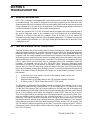
MCE HMC-PHC Hydraulic (ASME 2000) 42-02-1P01 C2 User manual
- Category
- Garage Door Opener
- Type
- User manual

MOTION CONTROL ENGINEERING, INC.
11380 WHITE ROCK ROAD
RANCHO CORDOVA, CA 95742
TELEPHONE (916) 463-9200 FAX (916) 463-9201
CONTROLLER INSTALLATION MANUAL
HMC-1000 Series PHC
Programmable Hydraulic Controller
PART # 42-02-1P01 REV C.2 OCTOBER 2009

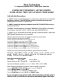
Hook Up Schedule
For Temporary Operation of A17.1 -2000 Hydro Controllers
EXERCISE EXTREME CAUTION WHEN
OPERATING THE ELEVATOR IN THIS MODE
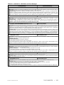
Critical Safety Precautions:
1. ALWAYS connect an individual jumper for each device, so when the device is installed
that jumper is removed. Note: NEVER jump out more circuits than necessary when
preparing the car to operate or conduct a test.
2. ALWAYS connect the temporary run buttons in the CAR TOP INSPECTION circuits so
they have top priority.
3. ALWAYS insert the temporary run button's EMERGENCY STOP SWITCH in the safety
circuit between terminals 17 and 18. NOT in series with the ENABLE button.
4. ALWAYS get the GOVERNOR/GOVERNOR SWITCH and SAFETIES/SAFETY OPERATOR
SWITCH (plank) operational as soon as possible.
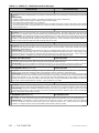
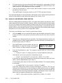
If the door operator, fire service and emergency power are not yet wired:
Remove wire from panel mount terminal DCL
Remove wire from terminal 47 on the SC-SB2K-H board
Jumper from 2 bus to panel mount terminal DPM
Jumper from 2 bus to terminal 36 on the SC-SB2K-H board
Jumper from 2 bus to panel mount terminal EPI (if present)
Jumper from 2F bus to terminal 38 on the SC-SB2K-H board
Jumper from 2F bus to terminal FRSM on the SC-SB2K-H board
Jumper from 2F bus to terminal FRSA on the SC-SB2K-H board
Safeties, door locks and temporary run buttons, jump terminals as follows:
2 bus to 16, 2 bus to INCTI, 9 to 10, 9 to 10X, 9 to 11, 9 to 12, 9 to 12X, 9 to 13,
9 to 86F, 9 to 88F, 16 to 17, 18 to 20, 2CT to CD, 2CT to HD or IDL, 4 to UNL,
P1 to P2, remove wires from ACCEN and INICN
If rear doors are present also jump:
2CT to CDR 2CT to HDR 2 bus to DPMR
remove wires from 36R, 37R and 47R jump 2 bus to 36R
If you have earthquake operation: jumper from CW1 to CW2 and SSI to EQ24
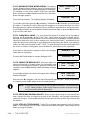
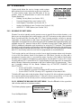
Install Temporary Run Buttons as follows (refer to area #6 of job prints):
Connect EMERGENCY STOP SWITCH between terminals 17 and 18
Connect ENABLE button to terminal INCTI
Connect UP button to terminal INCTU and ENABLE button
Connect DOWN button to terminal INCTD and ENABLE button
If you encounter any problems with A17.1 (redundancy) faults, refer to
Section 5.6.5 for instructions on how to temporarily bypass the faults.

42-02-1P01 TABLE OF CONTENTS • i
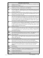
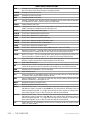
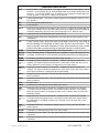
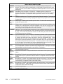
TABLE OF CONTENTS
IMPORTANT PRECAUTIONS AND NOTES ................................. viii
SECTION 1
PRODUCT DESCRIPTION
1.0 General Information ...............................................1-1
1.1 Car Controller Physical Description ...................................1-1
1.2 Car Controller Functional Description.................................1-12
1.2.1 Car Operation Control (COC) .................................1-12
1.2.2 Car Communication Control (CCC) .............................1-14
1.2.3 Programming and Diagnostics Tools ...........................1-14
1.2.4 Duplexing ................................................1-14
1.3 Landing System Control Box .......................................1-15
SECTION 2
INSTALLATION
2.0 General Information ...............................................2-1
2.0.1 Site Selection ..............................................2-1
2.0.2 Environmental Considerations .................................2-1
2.0.3 Recommended Tools and Test Equipment ........................2-2
2.0.4 the Wiring Prints............................................2-2
2.1 Controller Installation ..............................................2-3
2.1.1 Controller Wiring Guidelines...................................2-3
2.2 General Wiring Guidelines ..........................................2-4
2.2.1 Ground Wiring .............................................2-4
2.2.2 Main Ac Power .............................................2-5
2.2.3 Pump Motor Wiring..........................................2-5
2.3 Hoistway Control Equipment Installation ...............................2-5
2.3.1 Installing the Landing System ..................................2-5
2.3.2 Installing the Hoistway Limit Switches ...........................2-5
2.3.3 Installing the Landing System Control Box (LS-QUTE) ...............2-6
2.3.4 Installing the Magnetic Strips on the Steel Tape ....................2-6
2.3.5 Door Position Monitor Switch (If Used)...........................2-7

• TABLE OF CONTENTS 42-02-1P01ii
SECTION 3
START-UP SEQUENCE
3.0 General Information ...............................................3-1
3.1 Ground Check ...................................................3-1
3.2 Before Applying Power.............................................3-1
3.3 Applying Power ..................................................3-2
3.3.1 Initial Adjustments and Power Phasing...........................3-2
3.3.2 Moving the Elevator on Inspection ..............................3-3
3.3.3 Preparing the Car to Run on Automatic Operation ..................3-4
3.4 Preparation for Final Adjustment .....................................3-4
SECTION 4
FINAL ADJUSTMENT
4.0 General Information ...............................................4-1
4.1 Running on Automatic Operation .....................................4-1
4.1.1 Diagnostic Messages and Input/output Signals ....................4-1
4.1.2 a Few Words about Absolute Floor Encoding ......................4-2
4.1.3 Registering Car Calls ........................................4-3
4.1.4 Test Mode Operation ........................................4-3
4.1.5 Switching to Automatic Operation...............................4-4
4.2 Final Adjustments ................................................4-4
4.2.1 Door Operator Adjustments ...................................4-4
4.2.2 Hydraulic Valves............................................4-5
4.2.3 Slowdown and Limit Switches..................................4-5
4.2.4 Hall Calls .................................................4-5
4.2.5 Options...................................................4-5
4.2.6 Door Open/close Protection ...................................4-5
4.2.7 Motor Limit Timer ...........................................4-5
4.2.8 Valve Limit Timer ...........................................4-5
4.2.9 Stuck Button Protection ......................................4-5
4.2.10Relevel Operation...........................................4-5
SECTION 5
THE COMPUTER
5.0 About the PHC Series .............................................5-1
5.1 The MC-PCA-OA-2K Computer Panel - Your Tool for Programming, Diagnostics and
Data Communication ..............................................5-1
5.1.1 Indicators .................................................5-1
5.1.1.1 Computer on Light ....................................5-1
5.1.1.2 Vertical Status Indicator Lights ..........................5-1
5.1.1.3 Diagnostics LCD Display...............................5-2

42-02-1P01 TABLE OF CONTENTS • iii
5.1.2 Switches, Buttons & Adjustments...............................5-2
5.1.2.1 Computer Reset Pushbutton ............................5-2
5.1.2.2 N, S, +, & - Pushbuttons ...............................5-2
5.1.2.3 Mode Selection F1-F8 Function Switches ..................5-3
5.1.2.4 LCD Contrast Adjustment Trimpot........................5-3
5.1.3 Terminals .................................................5-3
5.1.3.1 Power Supply Terminal ................................5-3
5.1.3.2 Communication Port for Duplexing .......................5-3
5.1.3.3 Com Port 1 and 2 .....................................5-3
5.1.4 Status Displays.............................................5-3
5.2 Computer Security ................................................5-3
5.2.1 Password .................................................5-4
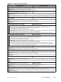
5.3 Diagnostic Mode .................................................5-4
5.3.1 Getting into Diagnostic Mode ..................................5-4
5.3.2 Function of N Pushbutton.....................................5-4
5.3.3 Function of S Pushbutton .....................................5-5
5.3.4 Function of + Pushbutton .....................................5-5
5.3.5 Function of
Pushbutton .....................................5-5
5.3.6 Format of Lcd Display........................................5-5
5.3.6.1 Normal Display .......................................5-5
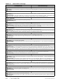
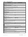
5.3.6.2 Status Message......................................5-6
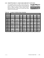
5.3.6.3 Elevator Position ....................................5-33
5.3.6.4 Computer Internal Memory ............................5-33
5.3.7 Troubleshooting Using the Computer's Internal Memory ............5-34
5.3.8 Troubleshooting Specific Problems ............................5-36
5.3.8.1 Problem: the BFD/TFD Error Message Is Flashing on the Display5-36
5.3.8.2 Problems with Calls ..................................5-38
5.3.8.3 Problems with Doors .................................5-38
5.3.9 Setting Parameters (Options) to Default Values ...................5-38
5.4 Program Mode ..................................................5-39
5.4.1 General Description of Program Mode ..........................5-39
5.4.1.1 Viewing Menus on the Lcd Display ......................5-39
5.4.1.2 Viewing Options Within a Menu.........................5-40
5.4.1.3 Changing a Value ...................................5-40
5.4.1.4 Saving the New Values ...............................5-40
5.4.1.5 Restoring Original Values .............................5-40
5.4.1.6 Step-by-step Example ................................5-40
5.4.2 Basic Feature Menu Options .................................5-42
5.4.2.1 Simplex or Duplex? ..................................5-42
5.4.2.2 Operation (Dispatching Operation) ......................5-42
5.4.2.3 Top Landing Served? (Simplex) /
Top Landing for this Car? (Duplex) ......................5-42
5.4.2.4 Car Doors Are Walk-thru? (Simplex) /
this Cars Doors Walk-thru? (Duplex)................5-42

• TABLE OF CONTENTS 42-02-1P01iv
5.4.2.5 Car Serves Frnt/flr 1? (Simplex) /
Car Serves Frnt/flr 1? (Duplex) ......................... 5-42
5.4.2.6 Car Serves Rear/flr 1? (Simplex) /
Car Serves Rear/flr 1? (Duplex) ........................ 5-42
5.4.2.7 Parking Floor....................................... 5-43
5.4.2.8 Alt. Parking Floor....................................5-43
5.4.2.9 Secondary Parking Floor..............................5-43
5.4.2.10 Lobby Floor .......................................5-43
5.4.2.11 Car Identifier ......................................5-43
5.4.2.12 Number of IOX Boards? .............................5-43
5.4.2.13 Number of I4O Boards?..............................5-43
5.4.2.14 Number of AIOX Boards? ............................5-43
5.4.3 Fire Service Menu Options...................................5-43
5.4.3.1 Fire Service Operation?............................... 5-43
5.4.3.2 Fire Phase 1 Main Floor ..............................5-43
5.4.3.3 Fire Phase 1 Alt. Floor................................5-44
5.4.3.4 Fire Svce. Code.....................................5-44
5.4.3.5 Fire Phase I 2nd Alt. Floor............................. 5-44
5.4.3.6 Bypass Stop Sw. On Phase 1? .........................5-44
5.4.3.7 Honeywell Fire Operation? ............................5-44
5.4.3.8 New York City Fire Phase 2 and ANSI 89? ................5-44
5.4.3.9 White Plains, NY Fire Code? .......................... 5-44
5.4.3.10 Mass 524 CMR Fire Code? ........................... 5-44
5.4.4 Door Operation Menu Options ................................5-44
5.4.4.1 Nudging?..........................................5-44
5.4.4.2 Stuck Photo Eye Protection?........................... 5-45
5.4.4.3 Sequential Door Oper. (F/R)? .......................... 5-45
5.4.4.4 Car Call Cancels Door Time? .......................... 5-45
5.4.4.5 Nudging During Fire Ph. 1?............................5-45
5.4.4.6 Retiring Cam Option? ................................ 5-45
5.4.4.7 Pre-opening? .......................................5-45
5.4.4.8 Mechanical Safety Edge? .............................5-46
5.4.4.9 Nudging Output/buzzer Only? ..........................5-46
5.4.4.10 D.C.B. Cancels Door Time? ..........................5-46
5.4.4.11 Leave Doors Open on PTI/ESS? .......................5-46
5.4.4.12 Nudging During Fire Phase 2? ........................ 5-46
5.4.4.13 Dir. Preference until DLK?............................5-46
5.4.4.14 Fully Manual Doors? ................................5-46
5.4.4.15 Cont. D.C.B. to Close Doors? .........................5-46
5.4.4.16 Cont. D.C.B. for Fire Ph 1? ...........................5-46
5.4.4.17 Moment. D.O.B. Door Opening ? .......................5-46
5.4.4.18 Doors to Open If Parked:.............................5-47
5.4.4.19 Doors to Open on Main Fire?..........................5-47
5.4.4.20 Doors to Open on Alt Fire? ........................... 5-47
5.4.4.21 Leave Doors Open on CTL? ..........................5-47
5.4.4.22 Limited Door Re-open Option .........................5-47
5.4.4.23 Reduce Hct with Photo Eye ...........................5-47
5.4.4.24 Leave Doors Open on EPI ............................5-47
5.4.4.25 Doors to Open If No Demand: .........................5-47
5.4.4.26 Const. Press Op. Bypass PHE? .......................5-47
5.4.4.27 Door Type Is Horizontal / Vertical ......................5-48
5.4.4.28 Front Door Cam Is Retiring / Fixed Type .................5-48
5.4.4.29 Rear Door Cam Is Retiring / Fixed Type .................5-48

42-02-1P01 TABLE OF CONTENTS • v
5.4.4.30 Prevent DCP Til Doors Close?.........................5-48
5.4.4.31 Moment D.C.B. to Close Doors? .......................5-48
5.4.4.32 Doors to Latch DOF?................................5-48
5.4.4.33 Doors to Latch DCF?................................5-48
5.4.5 Timer Menu Options........................................5-48
5.4.5.1 Short Door Timer....................................5-48
5.4.5.2 Car Call Door Timer..................................5-48
5.4.5.3 Hall Call Door Timer .................................5-48
5.4.5.4 Lobby Door Timer ...................................5-48
5.4.5.5 Nudging Timer......................................5-49
5.4.5.6 Time out of Svce. Timer (Range: 15-120 Seconds or None) . . . 5-49
5.4.5.7 Motor Limit Timer....................................5-49
5.4.5.8 Valve Limit Timer....................................5-49
5.4.5.9 Door Hold Input Timer ................................5-49
5.4.5.10 Parking Delay Timer ................................5-49
5.4.5.11 Fan/light Output Timer...............................5-49
5.4.5.12 Hospital Emerg. Timer...............................5-49
5.4.5.13 Door Open Protection Timer ..........................5-49
5.4.5.14 CTL Door Open Timer ...............................5-50
5.4.5.15 Door Buzzer Timer..................................5-50
5.4.6 Gongs/lanterns Menu Options ................................5-50
5.4.6.1 Mounted in Hall or Car? ...............................5-50
5.4.6.2 Double Strike on Down? ..............................5-50
5.4.6.3 PFG Enable Button? .................................5-50
5.4.6.4 Egress Floor Arrival Gong? / Main Egress Floor #...........5-50
5.4.7 Spare Inputs Menu Options ..................................5-50
5.4.8 Spare Outputs Menu Options .................................5-55
5.4.9 Extra Features Menu Options.................................5-58
5.4.9.1 PI Output Type .....................................5-58
5.4.9.2 Floor Encoding Inputs? ...............................5-58
5.4.9.3 Encode All Floors?...................................5-58
5.4.9.4 Emergency Power Operation? / Emergency Power Return Floor 5-59
5.4.9.5 Light Load Weighing? / Light Load Car Call Limit ...........5-59
5.4.9.6 Photo Eye Anti-nuisance? / Consec Stops W/O PHE Limit ....5-59
5.4.9.7 Peripheral Device?...................................5-59
5.4.9.8 Automatic Floor Stop Option? / Automatic Stop Floor #? ......5-60
5.4.9.9 CC Cancel W/dir Reversal?............................5-60
5.4.9.10 Cancel Car Calls Behind Car?.........................5-60
5.4.9.11 CE Electronics Interface? ............................5-60
5.4.9.12 Massachusetts Ems Service? / Ems Service Floor #........5-60
5.4.9.13 Master Software Key ................................5-60
5.4.9.14 PI Turned OFF If No Demand? ........................5-60
5.4.9.15 Hospital Emerg. Operation?...........................5-60
5.4.9.16 Fire Bypasses Hospital? .............................5-61
5.4.9.17 High Speed Delay after Run? .........................5-61
5.4.9.18 Sabbath Operation ..................................5-62
5.4.9.19 Leveling Sensor Enabled/disabled......................5-62
5.4.9.20 KCE Enable / Disable ...............................5-62
5.4.9.21 Analog Load Weigher? ..............................5-62
5.4.9.22 IND. Bypass Security?...............................5-62

• TABLE OF CONTENTS 42-02-1P01vi
5.4.9.23 ATS. Bypass Security? ..............................5-62
5.4.9.24 Car to Floor Return Floor............................. 5-62
5.4.9.25 Scrolling Speed .................................... 5-63
5.4.9.26 Low Oil Switch Contact ..............................5-63
5.4.9.27 OFRT Between Floors ............................... 5-63
5.4.10 ASME A17.1 2000 Features Menu ............................5-63
5.4.10.1 Hoistway Access? ..................................5-63
5.4.10.2 Number of Motor Starters ............................5-63
5.4.10.3 Min. Number of Motors .............................. 5-63
5.4.10.4 Soft-stop Timer ....................................5-63
5.4.10.5 Starter #1 Type .................................... 5-63
5.4.10.6 Starter #2 Type .................................... 5-63
5.4.10.7 Starter #3 Type .................................... 5-63
5.4.10.8 Y-D Transfer Timer .................................5-63
5.4.10.9 Up to Speed Timer ................................. 5-63
5.4.10.10 Y-D Open Transn. Timer ............................ 5-63
5.4.10.11 M Contactor Installed?..............................5-63
5.4.10.12 Starter Config ....................................5-63
5.4.10.13 Multiple Valves?...................................5-64
5.5 External Memory Mode ...........................................5-64
5.5.1 Getting into External Memory Mode ............................5-64
5.5.2 Function of N Pushbutton....................................5-64
5.5.3 Function of S Pushbutton....................................5-64
5.5.4 Function of + Pushbutton ....................................5-64
5.5.5 Function of – Pushbutton ....................................5-64
5.5.6 Troubleshooting Using External Memory Mode ...................5-65
5.6 System Mode...................................................5-68
5.6.1 Building Security Menu......................................5-68
5.6.1.1 Viewing the Building Security Menu......................5-68
5.6.1.2 Programming and Viewing the Security Codes ............. 5-69
5.6.2 Passcode Request Menu .................................... 5-70
5.6.3 Load Weigher Thresholds ...................................5-70
5.6.4 Analog Load Weigher Learn Function ..........................5-72
5.6.5 ASME A17.1 - 2000 Options ..................................5-74
5.6.5.1 Asme A17.1-2000 Redundancy Bypass. Jumper must Be
Installed to Activate...................................5-74
5.6.5.2 Long Term, Inspection Only ASME A17.1-2000 Redundancy
Bypass. Jumper must Be Installed to Activate ..............5-74
5.7 Duplexing......................................................5-75
5.7.1 Dispatching Algorithm ......................................5-75
5.7.2 Hardware Connections ......................................5-75
5.7.3 Troubleshooting ...........................................5-75

42-02-1P01 TABLE OF CONTENTS • vii
SECTION 6
TROUBLESHOOTING
6.0 General Information ...............................................6-1
6.1 Tracing Signals in the Controller .....................................6-1
6.2 Door Logic ......................................................6-4
6.3 Call Logic ......................................................6-8
6.3.1 Normal Operation...........................................6-8
6.3.2 Preparation for Troubleshooting Call Circuits ......................6-9
6.3.3 Troubleshooting the Call Circuits ...............................6-9
6.4 Car Does Not Move on Inspection or Automatic.........................6-13
6.5 PC Board Quick References .......................................6-14
6.6 Using the Optional CRT for Troubleshooting ...........................6-19
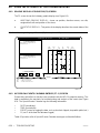
6.6.1 Graphic Display of Elevator (F3) Screen .........................6-19
6.6.2 MCE Special Events Calendar Entries (F7 - 1) Screen..............6-19
6.7 Using the MLT / VLT Data Trap .....................................6-22
6.8 ASME A17.1 - 2000 Fault Troubleshooting Tables .......................6-24
6.8.1 ASME A17.1 - 2000 Redundancy Fault Established Map ............6-24
6.8.2 ASME A17.1 - 2000 Redundancy Fault Data Trap .................6-25
6.8.3 ASME A17.1 - 2000 SC-HDIO Board Input Data Trap ..............6-25
6.8.4 Raw ASME A17.1 - 2000 SC-HDIO Board Input Map ...............6-26
6.8.5 Additional Flags and Variables Added for ASME 2000 ..............6-27
6.8.6 Formatted ASME A17.1 - 2000 SC-HDIO Board Input / Output Map . . . 6-28
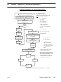
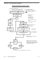
6.9 Starters - Sequence of Operation Flowcharts...........................6-30
APPENDIX
APPENDIX A - Original Programmed Values and the Record of Changes .................A-1
APPENDIX B - Nomenclature ...................................................A-4
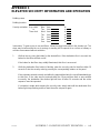
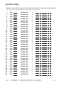
APPENDIX C - Elevator Security Information and Operation ...........................A-6
APPENDIX D - Flex-TALK Option ................................................A-8
1.0 Introduction And Theory of Operation ............................A-8
2.0 Diagnostics................................................A-8
3.0 Volume Control............................................A-10
4.0 Troubleshooting ...........................................A-10
5.0 Peripheral Equipment .......................................A-10
APPENDIX E - LS-QUTE Landing System Assembly Drawings ........................A-11

• TABLE OF CONTENTS 42-02-1P01viii
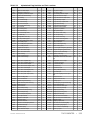
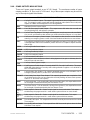
TABLES
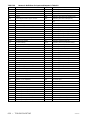
Table 5.4 Computer Internal Memory Chart ..............................5-33
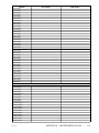
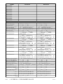
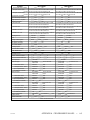
Table 5.5 Alphabetized Flags/Variables and Their Locations ................. 5-35
Table 5.6 Using the Program Mode ....................................5-40
Table 5.7 Computer External Memory Chart ............................. 5-66
Table 5.8 Computer’s Hospital Call and Eligibility Memory Chart ..............5-67
Table 6.1 Special Events Calendar Messages ............................6-18
Table 6.2 ASME A17.1 - 2000 Redundancy Fault Established Map ............6-22
Table 6.3 Redundancy Fault Established Data Trap .......................6-23
Table 6.4 ASME A17.1 - 2000 SC-HDIO Board Input Data Trap ..............6-23
Table 6.5 RAW ASME A17.1 - 2000 SC-HDIO Board Input Map ..............6-24
Table 6.6 Flags and Variables Added for ASME A17.1-2000 .................6-25
Table 6.7 Definitions for Flags and Variables in Table 6.6 ...................6-25
Table 6.8 Formatted SC-HDIO Board Input / Output Map ...................6-26
Table D.1 Diagnostic Table...........................................A-12
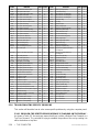
FIGURES
Figure 1.1 Typical Physical Layout ......................................1-2
Figure 1.2 HC-PCI/O Input Output Details .................................1-3
Figure 1.3 HC-CI/O-E Call Input/Output Board .............................1-4
Figure 1.4 HC-IOX Input/Output Expander Board ...........................1-4
Figure 1.5 HC-I4O Input/Output Expander Board ...........................1-4
Figure 1.6 SC-BAH Lock Bypass, Access, Overspeed, Emergency Brake Board . . . 1-5
Figure 1.7 SC-BAHR Lock Bypass Access Board with Rear Doors..............1-6
Figure 1.8 SC-HDIO High Density Input/Output Board .......................1-7
Figure 1.9 MC-PCA-OA2K Computer Board ...............................1-8
Figure 1.10 MC-PA-2K Peripherals Adapter Board (optional) ...................1-9
Figure 1.11 SC-SB2K-H Main Safety Relay Board ..........................1-10
Figure 1.12 Board Interconnects for ASME A17.1 -2000 Boards ................1-11
Figure 1.13 Car Controller Functional Layout .............................. 1-13
Figure 1.14 LS-QUTE-2K Car Top Control Box.............................1-15
Figure 1.15 LS-STAN5-2K Cartop Control Box .............................1-16
Figure 1.16 LS-STAN7-2K Cartop Control Box .............................1-16
Figure 2.1 Ground Wiring to Controller Cabinets ............................2-5
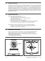
Figure 2.2 SLA Series Phase Monitor Wiring Diagrams ......................2-7
Figure 5.1 MC-PCA-OA-2K Computer Panel Board Layout ....................5-2
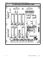
Figure 6.1 HC-PCI/O Power and Call Input/Output Board Quick Reference .......6-2
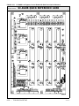
Figure 6.2 SC-SB2K-H Main Safety Relay Board Quick Reference .............6-3
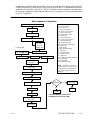
Figure 6.3 Door operation flowchart .....................................6-5
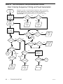
Figure 6.4 Door Closing Sequence, Timing and Fault Generation Flowchart ......6-5
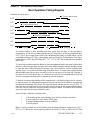
Figure 6.5 Door Operation Timing Diagram................................6-7
Figure 6.6 HC-CI/O Call Input/Output Board Quick Reference ................6-10
Figure 6.7 MC-PCA-OA-2K Main Computer Board Quick Reference ........... 6-14
Figure 6.8 MC-PA-2K Peripherals Adapter Board Quick Reference ............6-15
Figure 6.9 SC-HDIO High Density I/O Board Quick Reference ................6-16
Figure 6.10 SC-BAH Lock Bypass, Access Board Quick Reference .............6-17
Figure 6.11 SC-BAHR Lock Bypass, Access Board w/Rear Doors Quick Reference 6-18
Figure 6.12 Graphic Display of Elevator (F3) Screen (Color CRT) ..............6-19
Figure 6.13 Special Events Calendar - Display Special Event Entries (F7 - 1) Screen 6-20
Figure 6.14 WYE - DELTA Starter Sequence of Operation.................... 6-30
Figure 6.15 ATL Starter Sequence of Operation ............................6-31
Figure 6.16 Solid State Starter Sequence of Operation.......................6-32
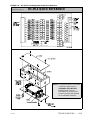
Figure 6.17 Standard PC Board Layout................................... 6-33
Figure D.1 Flex-Talk Board ...........................................A-11
Figure D.2 Speaker Dimensions .......................................A-13
Figure E.1 LS QUTE Enclosure Assembly................................A-14
Figure E.2 LS QUTE Wiring Diagram ...................................A-15

42-02-1P01 PRECAUTIONS & NOTES • ix
IMPORTANT PRECAUTIONS & NOTES
We strongly recommend that you read this manual carefully before proceeding with installation.
Throughout this manual you will see icons followed by a WARNING, CAUTION, or NOTE.
These icons denote the following:
WARNING: Operating procedures and practices which, if not done correctly,
may result in personal injury or substantial damage to equipment.
CAUTION: Operating procedures and practices which, if not observed, may
result in some damage to equipment.
NOTE: Procedures, practices or information which are intended to be
immediately helpful and informative.
The following general rules and safety precautions must be observed for safe and reliable
operation of your system.
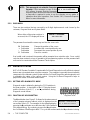
This controller may be shipped without the final running program. However you
may install the unit, hook-up and run your elevator on Inspection operation. Call
MCE about a week before you are ready to turn the elevator over to full
automatic operation so the running program can be shipped to you.
If you need to change a program chip on a computer board make sure you read the instructions
and know exactly how to install the new chip. Plugging these devices in backwards may
damage your chip.
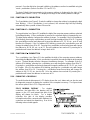
Elevator control products must be installed by experienced field personnel.
This manual does not address code requirements. The field personnel must
know all the rules and regulations pertaining to the safe installation and
running of elevators.
This equipment is an O.E.M. product designed and built to comply with ASME A17.1,
CAN/CSA-B44.1/ASME-A17.5 and National Electrical Code and must be installed by a qualified
contractor. It is the responsibility of the contractor to make sure that the final installation
complies with any local codes and is installed safely.
The 3-phase AC power supply to this equipment must come from a fused disconnect switch
or circuit breaker that is sized in conformance with all applicable national, state and local
electrical codes, in order to provide the necessary overload protection for the Drive Unit and
motor. Incorrect motor branch circuit protection will void the warranty and may create a
hazardous condition.

• PRECAUTIONS & NOTES 42-02-1P01x
Proper grounding is vitally important to the safe and successful operation of
your system. Bring your ground wire to the system subplate. You must choose
the proper conductor size and minimize the resistance to ground by using
shortest possible routing. See National Electrical Code Article 250-95, or the
related local applicable code.
Before applying power to the controller, physically check all power resistors and
other components inside the controller. Components loosened during shipment
may cause damage. Please make sure that all the safety relays on the SC-
SB2K board are properly seated in their sockets by pushing each relays gently
into its socket.
You must not connect the output triacs directly to a hot bus (2, 3 or 4 bus). This
can damage the triacs. PIs, direction arrows and terminals 40 & 42 are
examples of outputs that can be damaged this way. Note: miswiring terminal
39 into 40 can damage the fire warning indicator triac.
The HC-PCI/O and HC-CI/O-E boards are equipped with quick disconnect
terminals. During the original installation, you may want to remove the terminal
connector, hook up your field wires to it, test it for no shorts to ground (1 bus)
and to terminals 2, 3 and 4 before plugging these terminals back into the PC
boards.
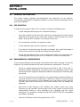
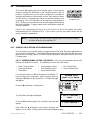
ENVIRONMENTAL CONSIDERATIONS:
Keep the machine room clean. Controllers are generally in NEMA 1 enclosures. Do not install the
controller in a dusty area. Do not install the controller in a carpeted area. Keep room temperature
between 32
F and 104 F (0 to 40 C). Avoid condensation on the equipment. Do not install the
controller in a hazardous location and where excessive amounts of vapors or chemical fumes
may be present. Make sure that the power line fluctuations are within +
10%.
The controller should be installed nearest to the hoist motor, such that length of the connecting
wires should not exceed more than 100 feet. If wire from controller to hoist motor is more than
100 feet, contact MCE.
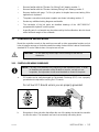
CONTROLLER OR GROUP ENCLOSURES WITH AIR CONDITIONING
If your controller or group enclosure is equipped with an air conditioning unit, observe the
following precautions (failure to do so can result in water condensation inside the enclosure):
• Ensure the integrity of the NEMA 12 or 4 enclosure is maintained by using sealed
knockouts and by sealing any holes created during installation.
• Do not run the air conditioner unit when the doors are open.
• To avoid damaging the compressor, if the air conditioner is turned off while it is running,
wait at least five minutes before turning power on again.
• Observe the manufacture’s recommended maintenance and optimum thermostat setting
of 75
o
F (see Operator’s Manual).
• Ensure the air conditioner unit’s drain hose remains open.

42-02-1P01 PRECAUTIONS & NOTES • xi
LIMITED WARRANTY
Motion Control Engineering (manufacturer) warrants its products for a period of 15 months from the date of
shipment from its factory to be free from defects in workmanship and materials. Any defect appearing more than
15 months from the date of shipment from the factory shall be deemed to be due to ordinary wear and tear.
Manufacturer, however, assumes no risk or liability for results of the use of the products purchased from it,
including, but without limiting the generality of the forgoing: (1) The use in combination with any electrical or
electronic components, circuits, systems, assemblies or any other material or equipment (2) Unsuitability of this
product for use in any circuit, assembly or environment. Purchasers’ rights under this warranty shall consist
solely of requiring the manufacturer to repair, or in manufacturer's sole discretion, replace free of charge, F.O.B.
factory, any defective items received at said factory within the said 15 months and determined by manufacturer
to be defective. The giving of or failure to give any advice or recommendation by manufacturer shall not
constitute any warranty by or impose any liability upon the manufacturer. This warranty constitutes the sole and
exclusive remedy of the purchaser and the exclusive liability of the manufacturer, AND IN LIEU OF ANY AND
ALL OTHER WARRANTIES, EXPRESSED, IMPLIED, OR STATUTORY AS TO MERCHANTABILITY,
FITNESS, FOR PURPOSE SOLD, DESCRIPTION, QUALITY PRODUCTIVENESS OR ANY OTHER MATTER.
In no event will the manufacturer be liable for special or consequential damages or for delay in performance of
this warranty.
Products that are not manufactured by MCE (such as drives, CRT's, modems, printers, etc.) are not covered
under the above warranty terms. MCE, however, extends the same warranty terms that the original
manufacturer of such equipment provide with their product (refer to the warranty terms for such products in their
respective manual).

42-02-1P01 PRODUCT DESCRIPTION •
1-1
SECTION 1
PRODUCT DESCRIPTION
1.0 GENERAL INFORMATION
MCE’s HMC-1000 Series PHC programmable elevator controller is designed to exhibit the
characteristics listed below in a hydraulic elevator installation. The Series PHC controller was
designed to save time during installation and troubleshooting, but it is still very important that
the field personnel who work with this equipment familiarize themselves with this manual before
attempting to install the equipment.
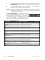
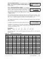
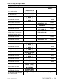
PRINCIPAL CHARACTERISTICS
Number of Stops 16 Environment:
Maximum Number of Cars 2 32
to 104 F (0 to 40 C) ambient
Field Programmable 12,000 ft altitude
95% humidity
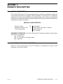
EQUIPMENT CATEGORIES - The HMC-1000 Series PHC hydraulic controller consists of three
major pieces of equipment:
Controller Unit
Car Top Selector (Landing System)
Peripherals
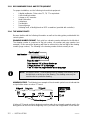
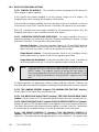
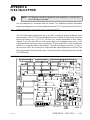
1.1 CAR CONTROLLER PHYSICAL DESCRIPTION
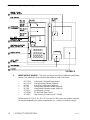
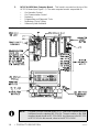
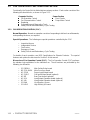
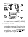
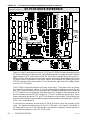
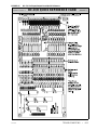
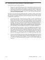
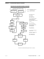
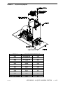
Figure 1.1 shows a typical layout of the Car Controller in a standard MCE cabinet. A brief
description of each block follows:

• PRODUCT DESCRIPTION 42-02-1P01
1-2
FIGURE 1.1 Typical Physical Layout
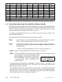
1. INPUT/OUTPUT BOARDS - This block consists of a number of different Input/Output
boards. The following is a list of boards that could be used in this block:
• HC-PCI/O Power and Call Input/Output board
• HC-CI/O-E Call Input/Output board (optional)
• HC-RD Rear Door Logic board (optional)
• HC-IOX Input/Output Expander board (optional)
• HC-I4O Input/Output Expander board (optional)
• SC-BAH Lock Bypass, Access.
• SC-BAHR SC-BAH with Rear Doors
• SC-HDIO High Density I/O board for A17.1-2000
Note that the HC-CI/O-E, HC-RD, HC-IOX and HC-I4O boards are optional and may
be required depending on system requirements (i.e., number of landings served).

42-02-1P01 PRODUCT DESCRIPTION •
1-3
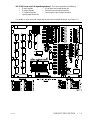
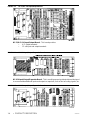
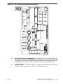
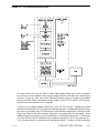
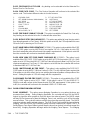
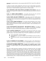
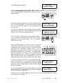
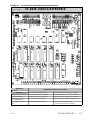
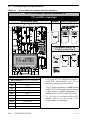
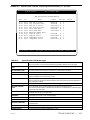
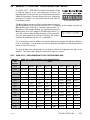
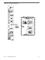
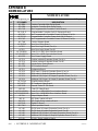
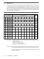
HC-PCI/O Power and Call Input/Output board - This board provides the following:
• 22 input signals • 10 call input and output terminals
• 12 output signals • 2 direction arrow output terminals
• PI output terminals • 1 passing floor gong output terminal
• 2 gong output terminals
For details of each input and output signal and the associated terminals, see Figure 1.2.
FIGURE 1.2 HC-PCI/O Input Output Details

• PRODUCT DESCRIPTION 42-02-1P01
1-4
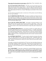
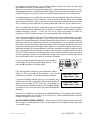
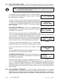
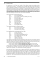
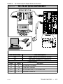
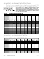
FIGURE 1.3 HC-CI/O-E Call Input/Output Board
HC-CI/O-E Call Input/Output Board - This board provides:
• 4 PI output terminals
• 12 call input and output terminals
FIGURE 1.4 HC-IOX Input/Output Expander Board
HC-IOX Input/Output Expander Board - This is a multi-purpose input/output board designed
to accommodate additional inputs and outputs as required, such as floor encoding signals, etc.
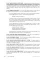
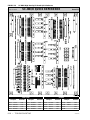
FIGURE 1.5 HC-I4O Input/Output Expander Board

42-02-1P01 PRODUCT DESCRIPTION •
1-5
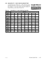
HC-I4O Input/Output Expander Board - This is a multi-purpose input/output board designed
to accommodate additional inputs and outputs as required.
HC-RD Rear Door Logic Board - This board (not shown) provides the inputs and outputs
required for independent rear doors.
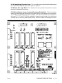
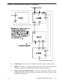
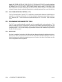
SC-BAH Lock Bypass, Access, Overspeed, Emergency Brake Board - This board contains
inputs, logic and outputs that perform the lock bypass function and inspection access operation.
The Car Door and Hoistway Door bypass switches are located on this board. Five test pins on
the board (TP1, TP2 and TPAB) are available for inspection and testing of the redundancy
checking logic for the force-guided (safety) relays. Refer to Chapter 4 for testing procedures.
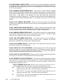
FIGURE 1.6 SC-BAH Lock Bypass, Access, Overspeed, Emergency Brake Board

• PRODUCT DESCRIPTION 42-02-1P01
1-6
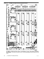
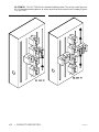
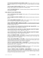
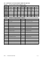
FIGURE 1.7 SC-BAHR Lock Bypass Access Board with Rear Doors
SC-BAHR (SC-BAH with Rear Doors) Lock Bypass, Access, Overspeed, Emergency
Brake Board - This board is the same as the SC-BAH with additional logic and relays for rear
doors.

42-02-1P01 PRODUCT DESCRIPTION •
1-7
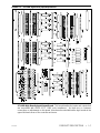
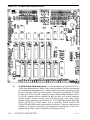
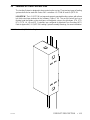
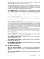
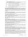
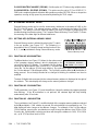
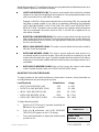
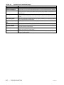
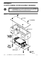
FIGURE 1.8 SC-HDIO High Density Input/Output Board
SC-HDIO High Density Input/Output Board - This board handles the inputs and outputs that
are associated with ASME A17.1 -2000 code compliance. As there are no customer
connections or adjustments on this board, it has been mounted behind the logic boards in the
upper left-hand corner of the controller enclosure.
Page is loading ...
Page is loading ...
Page is loading ...
Page is loading ...
Page is loading ...
Page is loading ...
Page is loading ...
Page is loading ...
Page is loading ...
Page is loading ...
Page is loading ...
Page is loading ...
Page is loading ...
Page is loading ...
Page is loading ...
Page is loading ...
Page is loading ...
Page is loading ...
Page is loading ...
Page is loading ...
Page is loading ...
Page is loading ...
Page is loading ...
Page is loading ...
Page is loading ...
Page is loading ...
Page is loading ...
Page is loading ...
Page is loading ...
Page is loading ...
Page is loading ...
Page is loading ...
Page is loading ...
Page is loading ...
Page is loading ...
Page is loading ...
Page is loading ...
Page is loading ...
Page is loading ...
Page is loading ...
Page is loading ...
Page is loading ...
Page is loading ...
Page is loading ...
Page is loading ...
Page is loading ...
Page is loading ...
Page is loading ...
Page is loading ...
Page is loading ...
Page is loading ...
Page is loading ...
Page is loading ...
Page is loading ...
Page is loading ...
Page is loading ...
Page is loading ...
Page is loading ...
Page is loading ...
Page is loading ...
Page is loading ...
Page is loading ...
Page is loading ...
Page is loading ...
Page is loading ...
Page is loading ...
Page is loading ...
Page is loading ...
Page is loading ...
Page is loading ...
Page is loading ...
Page is loading ...
Page is loading ...
Page is loading ...
Page is loading ...
Page is loading ...
Page is loading ...
Page is loading ...
Page is loading ...
Page is loading ...
Page is loading ...
Page is loading ...
Page is loading ...
Page is loading ...
Page is loading ...
Page is loading ...
Page is loading ...
Page is loading ...
Page is loading ...
Page is loading ...
Page is loading ...
Page is loading ...
Page is loading ...
Page is loading ...
Page is loading ...
Page is loading ...
Page is loading ...
Page is loading ...
Page is loading ...
Page is loading ...
Page is loading ...
Page is loading ...
Page is loading ...
Page is loading ...
Page is loading ...
Page is loading ...
Page is loading ...
Page is loading ...
Page is loading ...
Page is loading ...
Page is loading ...
Page is loading ...
Page is loading ...
Page is loading ...
Page is loading ...
Page is loading ...
Page is loading ...
Page is loading ...
Page is loading ...
Page is loading ...
Page is loading ...
Page is loading ...
Page is loading ...
Page is loading ...
Page is loading ...
Page is loading ...
Page is loading ...
Page is loading ...
Page is loading ...
Page is loading ...
Page is loading ...
Page is loading ...
Page is loading ...
Page is loading ...
Page is loading ...
Page is loading ...
Page is loading ...
Page is loading ...
Page is loading ...
Page is loading ...
Page is loading ...
Page is loading ...
Page is loading ...
Page is loading ...
Page is loading ...
Page is loading ...
Page is loading ...
Page is loading ...
Page is loading ...
Page is loading ...
Page is loading ...
Page is loading ...
Page is loading ...
Page is loading ...
Page is loading ...
Page is loading ...
Page is loading ...
Page is loading ...
Page is loading ...
Page is loading ...
-
 1
1
-
 2
2
-
 3
3
-
 4
4
-
 5
5
-
 6
6
-
 7
7
-
 8
8
-
 9
9
-
 10
10
-
 11
11
-
 12
12
-
 13
13
-
 14
14
-
 15
15
-
 16
16
-
 17
17
-
 18
18
-
 19
19
-
 20
20
-
 21
21
-
 22
22
-
 23
23
-
 24
24
-
 25
25
-
 26
26
-
 27
27
-
 28
28
-
 29
29
-
 30
30
-
 31
31
-
 32
32
-
 33
33
-
 34
34
-
 35
35
-
 36
36
-
 37
37
-
 38
38
-
 39
39
-
 40
40
-
 41
41
-
 42
42
-
 43
43
-
 44
44
-
 45
45
-
 46
46
-
 47
47
-
 48
48
-
 49
49
-
 50
50
-
 51
51
-
 52
52
-
 53
53
-
 54
54
-
 55
55
-
 56
56
-
 57
57
-
 58
58
-
 59
59
-
 60
60
-
 61
61
-
 62
62
-
 63
63
-
 64
64
-
 65
65
-
 66
66
-
 67
67
-
 68
68
-
 69
69
-
 70
70
-
 71
71
-
 72
72
-
 73
73
-
 74
74
-
 75
75
-
 76
76
-
 77
77
-
 78
78
-
 79
79
-
 80
80
-
 81
81
-
 82
82
-
 83
83
-
 84
84
-
 85
85
-
 86
86
-
 87
87
-
 88
88
-
 89
89
-
 90
90
-
 91
91
-
 92
92
-
 93
93
-
 94
94
-
 95
95
-
 96
96
-
 97
97
-
 98
98
-
 99
99
-
 100
100
-
 101
101
-
 102
102
-
 103
103
-
 104
104
-
 105
105
-
 106
106
-
 107
107
-
 108
108
-
 109
109
-
 110
110
-
 111
111
-
 112
112
-
 113
113
-
 114
114
-
 115
115
-
 116
116
-
 117
117
-
 118
118
-
 119
119
-
 120
120
-
 121
121
-
 122
122
-
 123
123
-
 124
124
-
 125
125
-
 126
126
-
 127
127
-
 128
128
-
 129
129
-
 130
130
-
 131
131
-
 132
132
-
 133
133
-
 134
134
-
 135
135
-
 136
136
-
 137
137
-
 138
138
-
 139
139
-
 140
140
-
 141
141
-
 142
142
-
 143
143
-
 144
144
-
 145
145
-
 146
146
-
 147
147
-
 148
148
-
 149
149
-
 150
150
-
 151
151
-
 152
152
-
 153
153
-
 154
154
-
 155
155
-
 156
156
-
 157
157
-
 158
158
-
 159
159
-
 160
160
-
 161
161
-
 162
162
-
 163
163
-
 164
164
-
 165
165
-
 166
166
-
 167
167
-
 168
168
-
 169
169
-
 170
170
-
 171
171
-
 172
172
-
 173
173
-
 174
174
-
 175
175
-
 176
176
-
 177
177
-
 178
178
-
 179
179
-
 180
180


MCE HMC-PHC Hydraulic (ASME 2000) 42-02-1P01 C2 User manual
- Category
- Garage Door Opener
- Type
- User manual
Ask a question and I''ll find the answer in the document
Finding information in a document is now easier with AI
Related papers
-
MCE VVMC-SCR Turbo DF 42-02-7001 F1 User manual
-
-
-
-
-
MCE Element Hydraulic Controller 42-02-1P26 C4 User manual
-
-
-
-
Other documents
-
CAS QD8RW10PRF User manual
-
Monarch NICE 5000 User manual
-
 K-Tech ET98A User manual
-
 Smartrise C4 User manual
-
-
 Suzhou Monarch Control Technology MCTC-HCB-A User manual
-
Skov DOL 99-2 feed weigher User manual
-
-
NetSafety Millennium Rackmount Controller Owner's manual
-


