Page is loading ...

XTLplus-GW
Quick Start Guide
LT-1714 18252 © 2018 Digital Monitoring Products, Inc.
1SELECT A LOCATION
The XTLplus-GW is designed to be placed on a table
or other flat surface. Choose a central location in the
home to allow the panel to communicate clearly with the
system's sensors and keypads.
2CONNECT THE XTLplus-GW TO THE
NETWORK
If you are using a SecureCom Wireless Access Point
(WAP), power it up now.
If you are working with another type of router, move on to
Step 3 and then press the WPS button on the customer’s
router within 2 minutes of powering the XTLplus-GW.
If the router does not have a WPS button, move on to
Step 3 and then connect a keypad (a guide is included
with each keypad to walk you through the set-up
process). Once the keypad is set up, follow the on-screen
prompts to choose a network.
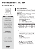
3POWER UP THE XTLplus-GW
Plug the 12VDC power supply connector into the port on
the back of the XTLplus-GW. Plug the other end of the
power supply into a dedicated wall outlet not controlled
by a switch. See Figure 1.
Figure 1: XTLplus-GW Power Connection
12VDC
Power Port
Power
Indicator LED
Dedicated
Outlet
XTLplus-GW
Quick Start Guide
LT-1714 18252 © 2018 Digital Monitoring Products, Inc.
1SELECT A LOCATION
The XTLplus-GW is designed to be placed on a table
or other flat surface. Choose a central location in the
home to allow the panel to communicate clearly with the
system's sensors and keypads.
2CONNECT THE XTLplus-GW TO THE
NETWORK
If you are using a SecureCom Wireless Access Point
(WAP), power it up now.
If you are working with another type of router, move on to
Step 3 and then press the WPS button on the customer’s
router within 2 minutes of powering the XTLplus-GW.
If the router does not have a WPS button, move on to
Step 3 and then connect a keypad (a guide is included
with each keypad to walk you through the set-up
process). Once the keypad is set up, follow the on-screen
prompts to choose a network.
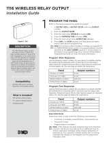
3POWER UP THE XTLplus-GW
Plug the 12VDC power supply connector into the port on
the back of the XTLplus-GW. Plug the other end of the
power supply into a dedicated wall outlet not controlled
by a switch. See Figure 1.
Figure 1: XTLplus-GW Power Connection
12VDC
Power Port
Power
Indicator LED
Dedicated
Outlet
/