Page is loading ...

INSTALLATION AND PROGRAMMING GUIDE
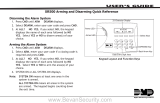
9800 Series
Graphic Touchscreen Keypad
System Armed
TO DAY
WEDNESDAY
82
98 77
CURRENT
HI LO
85 68
HI LO
98 77
Panic
Chime
Reset
Favorites
MON 5:35 PMMON 5:35 PM
ARMED


TABLE OF CONTENTS
About the Keypad ......................... 1
Keypad Features ............................ 2
Programmable Carousel Menu .......................3
Enter Characters ........................... 4
Select a Location ...........................6
Install the Keypad ..........................7
Remove the Cover ...............................................7
Install the 9862 Keypad .....................................8
Install the 9862USB Keypad ........................... 10
Connect the Keypad .......................................... 12
Program the Keypad ................... 14
Custom Card Format ................... 16
Carousel Z-Wave Items ..................................... 22
Shortcut Items ......................................................23
Test the Keypad ...........................24
Additional Programming ............25
Update the Keypad ............................................25
Credential Compatibility ..................................26
End User Training ........................ 27
Arm and Disarm the System ...........................27
Replace the Keypad Battery ...........................29
Public Card Formats ...................30
Credentials ....................................31
Compliance Specifications ........ 32
Certifications ................................33
FCC Information ..........................34
Industry Canada Information ..... 35


9800 Series Installation and Programming Guide 1
ABOUT THE KEYPAD
9800 Series Wireless Graphic Touchscreen Keypads oer flexible features and
functionality. Each keypad provides:
• AC Power/Armed LED
• Full color touchscreen display
• Built-in proximity card reader
• Internal speaker
• Wireless communication
• 12VDC plug-in power supply (9862) and wire harness
• 5VDC plug-in power supply (9862USB)
• Internal rechargeable 3.7V lithium battery
• Micro SD card slot for customized logo
• Icon-driven operation
• Wall tamper protection (9862)
• Two snap-in deskstand legs (9862USB)
• Optional backboxes for conduit or wall-mount applications

9800 Series Installation and Programming Guide 2
KEYPAD FEATURES
System Armed
TO DAY
WEDNESDAY
82
98 77
CURRENT
HI LO
85 68
HI LO
98 77
Panic
Chime
Reset
Favorites
MON 5:35 PMMON 5:35 PM
ARMED
Armed/Power
LEDs &
Proximity Reader
Dealer Logo
Carousel Menu
Local
Weather
Homescreen
Shield
Press the
Navigation Arrows
or touch and drag
the menu to scroll
Figure 1: Keypad Features

9800 Series Installation and Programming Guide 3
PROGRAMMABLE CAROUSEL MENU
The carousel menu allows the user to pick and choose what displays within the carousel
menu on the home screen. Press Options in the carousel menu. From here, adjust
the keypad screen brightness, keypad tone, and keypad volume. Press a box under
DisplayInMenu to select that option to display in the carousel menu. Press that box again
to deselect that option. See Figure2.
MODEL NUMBER 9800 V110 0961017
Display In Menu
Chime
Reset
Easy Exit
Check In
Brightness
Tone
Volume
Figure 2: Keypad Options

9800 Series Installation and Programming Guide 4
ENTER CHARACTERS
Number Pad
1. Choose a character from the table.
2. Identify the Number the character
correlates with and press that
number on the number pad.
3. Identify the Select Area for the
character and press that select area
on the keypad. Press that select area
again for the lowercase letter. See
Figure 3.
4. When the desired character displays
on the keypad, return to Step 1 to
enter another character or press CMD
if finished.
Standard Keyboard
• Press ABC to enter uppercase letters.
• Press abc to enter lowercase letters.
• Press !@# to enter special characters.
• Press 123 to enter numbers and to return to the number pad. See Figure 4.
NUMBER
SELECT AREA
1 2 3 4
1
A B C ( [ {
2
D E F ) ] }
3
G H I ! ^ ~
4
J K L ? “ |
5
M N O / \ `
6
P Q R & $
7
S T U @ %
8
V W X , =
9
Y Z Space : _ ;
0
- + . ‘ * < # >

9800 Series Installation and Programming Guide 5
Figure 4: Standard Keyboard
1 2 3 4
5 6 7 8
9 0
CMD
ABC DEF GHI JKL
MNO PQR STU VWX
YZ
ABC
!@#
123
q w e r t y u i
o p
a s d f g h j k l
z
x c v b n m CMD
Select Areas
1 2 3 4
5 6 7 8
9 0
CMD
ABC
!@#
ABC DEF GHI JKL
MNO PQR STU VWX
YZ
ENTER CODE:
Return
to Home
Screen
1 43
Figure 3: Number Pad
2
Uppercase/
Lowercase
Letters
Special
Characters
Number Pad

9800 Series Installation and Programming Guide 6
9800 Series Wireless Graphic Touchscreen Keypads provide a built–in survey capability
to allow one person to confirm keypad communication with the wireless receiver or panel.
This allows you to determine the best location for the keypad.
1. Press Options in the carousel menu.
2. Press the installer options icon at the bottom-left corner of the screen.
3. Enter 3577 (INST) and press CMD.
4. Press the select key under KPD RF to start the survey communication. The keypad
displays its wireless serial number and RF SURVEY. Determine if communication is
confirmed or faulty.
Confirmed: When successful communication has been established, the AC
Power/Armed LED turns blue.
Faulty: If communication has not been established, the keypad AC Power/
Armed LED turns red. Relocate the device or wireless receiver until the survey
LED confirms clear communication.
SELECT A LOCATION

9800 Series Installation and Programming Guide 7
INSTALL THE KEYPAD
REMOVE THE COVER
The keypad housing is made up of two parts:
the cover, which contains the circuit board and
components, and the base.
1. Insert a flat screwdriver into one of the
slots on the bottom of the keypad and lift
the screwdriver upward. Repeat with the
other slot.
2. Separate the cover from the base and
set the cover containing the keypad
components aside. See Figure 5.
1
Figure 5: Separate the
Keypad Housing
Cover
Base

9800 Series Installation and Programming Guide 8
INSTALL THE 9862 KEYPAD
9862 Keypads are designed to install on any single-gang switch box or flat surface. Do
not mount on metallic surfaces or boxes. Follow these steps to mount the keypad on a
wall or flat surface.
1. Run 18-22 AWG wire from the desired keypad location to the nearest available,
non-switched outlet.
2. Connect the supplied 4-pin power supply harness to the 18-22 AWG wire.
Please note that the wire with the white stripe needs to connect to the
positive (usually red) wire.
3. Feed the power supply harness through the case. See Figure 6.
4. Using the supplied screws, secure the keypad base to a wall or box. Ensure the
tamper switch makes proper contact with the wall.
5. While observing polarity, connect the positive (red) wire to the positive
terminal on the power supply. Connect the black wire to the negative terminal
on the power supply.
6. Plug in the power supply.
7. Connect the other end of the power supply harness to the 4-pin power
connector on the keypad without removing the PCB from the keypad housing,
and snap the keypad into the base
2

9800 Series Installation and Programming Guide 9
+
_
Figure 6: Install the 9862 Keypad

9800 Series Installation and Programming Guide 10
INSTALL THE 9862USB KEYPAD
9862USB Wireless Graphic Touchscreen Keypads are intended for tabletop use. Follow
these steps to attach the desk stand legs and power the 9862USB keypad. See Figures 7,
8, and 9.
1. Insert one leg into the holes on the back of the keypad.
2. Slide the leg upwards until the leg firmly snaps into place. Repeat the process to
attach the second leg. See Figure 7.
3. Fit the transformer strap on the transformer, ensuring the strap slit is facing up and
the adapter plugs are fed through the strap plug openings. See Figure 8.
4. Feed the micro USB end of the power supply cable through the two slits in the
transformer strap, then plug the USB end into the USB port on the adapter.
5. Remove the center screw from the power outlet plate.
6. Plug the power supply into the outlet.
7. Place the outlet screw through the hole in the plastic strap and secure it into the
outlet.
8. Plug the micro USB end of the cable into the back of the keypad. See Figure 9.

9800 Series Installation and Programming Guide 11
Figure 8
Figure 7
Figure 9
Micro
USB
Transformer
and Strap

9800 Series Installation and Programming Guide 12
CONNECT THE KEYPAD
Connect the keypad to the panel by using one of the following options: Wireless
Keypad Association, Auto Pairing, or manually at the keypad in Device Setup. A
maximum of seven keypads can be paired with each panel.
Wireless Keypad Association
XTLplus/XTLtouch
1. Press Options in the carousel menu.
2. Press the installer options icon at the bottom-right corner of the screen.
3. Enter 3577 (INST) and press CMD.
4. Press KPD RF to start the RF survey communication. The keypad displays its
wireless serial number and RF SURVEY. When successful communication has
been established, the AC Power/Armed LED turns blue. If communication has
not been established, the LED turns red.
XT30/XT50 or XR150/XR550 Series Panels
Reset the panel three times. The yellow LED at the top of the panel will begin flashing
between each press. Wait for sixty seconds. When communication is confirmed, the
LED will turn green and will stay on steady.
3

9800 Series Installation and Programming Guide 13
Auto Pair
Auto pairing automatically connects your keypad to the panel. This option is only
available for Version 109 or higher keypads that do not have a previously assigned
house code. After powering the XTLplus/XTLtouch and the keypad, the keypad displays
PairingKeypad With System... and a ten minute pairing timer begins.
Confirmed: The keypad home screen displays, signaling that pairing is complete.
Faulty: The keypad displays Pairing Failed, followed by the Reset screen. Reset your
panel and press Pair to restart the pairing process. The panel will auto pair with
wireless keypads until it pairs with four keypads or until ten minutes have passed.
Device Setup
1. Program the keypad as a device in DEVICE SETUP.
2. Enter the eight-digit SERIAL# and continue to program the device as directed in
the appropriate panel programming guide.

9800 Series Installation and Programming Guide 14
PROGRAM THE KEYPAD
Refer to the appropriate panel programming guide as needed. Keep in mind that
operation for some programming options is restricted to the appropriate model. To access
the Keypad Options menu, press Options in the carousel menu. Press the Installer Options
or wrench icon and enter 3577 (INST) and press CMD.
Keypad Options
To program keypad options, press the select area under
KPD OPT. When finished programming, press STOP to save all
programming.
Default Keypad Message
Enter a custom message of up to sixteen characters to appear
at the top of the keypad display. Press any select area, enter a
new message, and press CMD. See Enter Characters.
Arm Panic Keys
Use this option to enable or disable the panic keys. Press the
icon name: PN (panic), EM (emergency), and FI (fire). Once
the panic option is enabled, an asterisk displays next to the
selected option(s).
KPD KPD
OPT DIAG STOP
DEFAULT KPD MSG:
ARM PANIC KEYS:
*PN *EM *FI

9800 Series Installation and Programming Guide 15
Arming/Disarming Wait Time
Select the number of seconds (1-9) the keypad should wait to
arm and disarm when an area system displays ALL? NO YES or
a H/S/A system waits during arming only. If NO or YES, or
HOME, SLEEP, or AWAY is not manually selected before the
delay expires, the keypad automatically selects YES or AWAY.
Select zero (0) to disable this feature. The delay also occurs
when a credential is presented for arming the H/S/A system.
Default is 2.
Enable Tamper
If the keypad is mounted on a wall, select YES to enable the
wall tamper. Default is NO.
ALL?: NO YES
DELAY: 2
ENABLE TAMPER?
NO YES

9800 Series Installation and Programming Guide 16
CUSTOM CARD FORMAT
Any Card Format
Select YES to allow all card reads to activate the door strike
relay. The door strike relay is activated for the length of time
programmed in ZN 3 REX TIME. No user code information is
sent to the panel. Default is NO.
Card Formats
Select the slot number (1-7) that you would like to program a
custom non-DMP card format into. Select 8 if you would like to
program a DMP card format. See Public Card Formats for
some publicly available card formats that can be used with the
keypad. Other private or custom formats may also be
compatible. Please contact the credential supplier or
manufacturer for the bit structure.
Format Name
Press any select area to rename the card format. Press CMD to
save and advance.
ANY CARD FORMAT
NO YES
CARD FORMATS
FORMAT NO: -
FORMAT NAME
*UNUSED*
/