Page is loading ...

INSTALLATION GUIDE
XTLtouch
TM


TABLE OF CONTENTS
About the XTLtouch .............. 1
Install the XTLtouch ..............2
Wall Mount (XTLtouch) ......................... 2
Desk Stand (XTLtouchUSB) ................2
In-Wall........................................................... 2
Wall Mount Installation .........3
Mount the Backplate .............................. 3
Install the 265LTE-V-GW .......................5
Wire for Power .......................................... 7
Desk Stand Installation .........9
Install the Desk Stand Legs ..................9
Power the XTLtouch .............................. 10
In Wall Installation ............... 11
Prepare for Backbox Installation........11
Install the Backbox ................................. 12
Install the XTLtouch in the Backbox 14
Additional Information ........15
Secondary Power Supply...................... 15
Replace the Battery .............................. 15
Accessories ............................17
Keypad Cover ........................................... 17
Transformer .............................................. 17
Cellular Communicator ........................ 17
Certifications ......................... 18
FCC Information ...................19
Industry Canada....................21

Information furnished is believed to be accurate and reliable.
This information is subject to change without notice.

Digital Monitoring Products | XTLtouch Installation Guide 1
ABOUT THE XTLtouch
The XTLtouch oers flexible features and functionality. It’s composed of an
XTLplus panel with an integrated 7872 Graphic Touchscreen Keypad, providing
a simple device to control and operate a system. The XTLtouch can be wall-
mounted, in wall mounted, or it can provide a simple deskstand option for
tabletop use.
The XTLtouch provides the following features and functionality:
• 5” graphic touchscreen keypad screen
• Three-part housing (cover, base, wall)
• On-board proximity reader designed to read DMP/HID credentials
• On-board Wi-Fi
• Z-Wave Plus support
• 2400mAh battery back-up
• 900MHz Wireless

XTLtouch Installation Guide | Digital Monitoring Products 2
INSTALL THE XTLtouch
Wall Mount (XTLtouch)
For wall mount installations, you will use the included backplate to mount the
XTLtouch to a wall.
Desk Stand (XTLtouchUSB)
For desk stand installations, you will use the included legs for tabletop use.
In-Wall
For in-wall installations, you will use an in wall backbox to mount the XTLtouch
into the wall, creating a flush wall mount look.
Pro Tip: Mount the XTLtouch near a wall outlet for the plug-in power supply.
The power supply should be located within 100 feet of the XTLtouch using
22 AWG wire.

Digital Monitoring Products | XTLtouch Installation Guide 3
WALL MOUNT INSTALLATION
Mount the Backplate
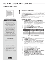
1. Press the tab and remove the backplate from the XTLtouch.
See Figure 1.
1
Figure 1: Removing the Backplate
Backplate
Tab

XTLtouch Installation Guide | Digital Monitoring Products 4
2. Use the include mounting template, level, and #6 screws to mount the
backplate to the wall. See Figure 2 for mounting hole locations.
Figure 2: Mounting Hole Locations
Level

Digital Monitoring Products | XTLtouch Installation Guide 5
2. Use the include mounting template, level, and #6 screws to mount the
backplate to the wall. See Figure 2 for mounting hole locations.
Install the 265LTE-V-GW Cellular Communicator (Optional)
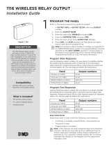
1. Remove the set screw from the bottom of the XTLtouch.
2. Remove the four screws from the back of the XTLtouch.
3. Separate the base from the panel and keypad. See Figure 3.
2
Figure 3: Installing the 265LTE-V-GW

XTLtouch Installation Guide | Digital Monitoring Products 6
4. Remove the backing from the flexible
antenna and place it inside the housing.
5. Snap the end of the antenna on to the
265LTE-V-GW antenna patch.
6. Insert the 265LTE-V-GW into the eight-
pin CELL MODULE header, keeping it
parallel to the XTLtouch.
7. Snap the 265LTE-V-GW on to the
stando and secure it in place.
8. Replace the base and secure it with the
four screws and the one set screw.
See Figure 4.
Figure 4: Connecting the Antenna

Digital Monitoring Products | XTLtouch Installation Guide 7
Wire for Power
See Figure 5 for wire routing instructions before wiring the XTLtouch for
power.
1. Connect the XTLtouch +DC terminal to the positive terminal on the
power supply.
2. Connect the XTLtouch -DC terminal to the negative terminal on the
power supply.
3. Plug the power supply into a 120 V AC 60Hz dedicated outlet that’s
not controlled by a switch.
4. Place the XTLtouch back on to the mounted backplate.
3

XTLtouch Installation Guide | Digital Monitoring Products 8
Figure 5: Routing Wires

Digital Monitoring Products | XTLtouch Installation Guide 9
DESK STAND INSTALLATION
See Steps 1 and 2 in Wall Mount installation to install the optional
265LTE-V-GW.
Install the Desk Stand Legs
1. Insert one leg into the holes in the back of the XTLtouch.
2. Slide the leg upwards until the leg firmly snaps into place. Repeat
steps 1 and 2 to install the other leg. See Figure 6.
1
Figure 6: Connecting the Desk stand Legs

XTLtouch Installation Guide | Digital Monitoring Products 10
Power the XTLtouch
1. Plug the micro USB end of the cable into the back of the keypad.
2. If desired, insert the cable into the strain relief to secure the XTLtouch
from being unattached from its power source.
3. Plug the power supply into an outlet. See Figure 7.
2
Figure 7: Strain Relief Option
Strain Relief

Digital Monitoring Products | XTLtouch Installation Guide 11
IN WALL INSTALLATION
Prepare for Backbox Installation
1. Place the included backbox
template on the wall in the desired
location.
2. Cut along the inside of the
template border line, ensuring to
not square the corners.
3. Place the two included #6 screws
approximately 1/4” into the two
locking tab holes on the rear wall
of the backbox.
1
Figure 8: Screw Locations

XTLtouch Installation Guide | Digital Monitoring Products 12
2
Install the Backbox
1. Route the 22 AWG wires through the bottom slot in the backbox.
2. Place the backbox in the wall space you created with the locking tabs
in a vertical position. See Figure 9.
Vertical Locking
Tab
Figure 9: Placing the Backbox in the Wall

Digital Monitoring Products | XTLtouch Installation Guide 13
3. Once in place, use a Number 2 Phillips screwdriver to tighten the #6
screws that are already in place. This allows the locking tabs to swing into
a horizontal position on both sides of the backbox.
Pro Tip: In some installations, it may be necessary to secure the
backbox to a wall stud. To do this, place the backbox in the wall
space you created and secure it to the wall stud by using the side
mounting holes. See Figure 10.
Figure 10: Securing the Backbox

XTLtouch Installation Guide | Digital Monitoring Products 14
3
Install the XTLtouch in the Backbox
1. See Wall Mount Installation to wire
the XTLtouch.
2. Insert the top of the XTLtouch into
the backbox at a slight angle until
the XTLtouch slots connect to the
backbox tabs.
3. Push the bottom of the keypad into
the backbox until the lower slots
snap in to place. See Figure 11.
See LT-1321 for additional backbox
mounting instructions.
Figure 11: Placing the XTLtouch

Digital Monitoring Products | XTLtouch Installation Guide 15
ADDITIONAL INFORMATION
SECONDARY POWER SUPPLY
The XTLtouch’s 2400mAh rechargeable standby battery is used to provide four
hours of battery power when DC power is not available. The battery is intended
for back power only and should not operate the panel on a daily basis.
If the battery is low or not plugged in to the battery connector, a low battery
condition is indicated by the panel. If a 24 hour standby battery is needed,
connect a 4800mAh battery.
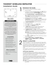
Replace the Battery
1. Remove the backplate from the XTLtouch.
2. Unplug the battery from the BAT connector and remove it from the PCB.
3. Place the new battery in the same location and secure it with the included
adhesive.
4. Re-plug the BAT connector.
5. Replace the backplate. See Figure 12.
Figure 11: Placing the XTLtouch

XTLtouch Installation Guide | Digital Monitoring Products 16
3.8V 4800mAh Rechargeable Battery
(required for 24 hour standby)
3.8V 2400mAh
Rechargeable
Battery
Figure 12: Replacing the Battery
/