Page is loading ...

Workrite Ergonomics | 800.959.9675 www.workriteergo.com 1 of 6
0.373"
#2 Drive
0.190"
1/2"
0.133"
#10-32 Thread
0.373"
#2 Drive
0.133"3/4"
0.190"
#10 Screw Size
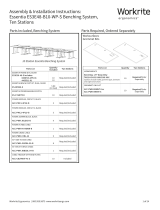
Jumper Cable Lengths:
36"w=15"
42"w=21"
48"w=27"
54"w=33"
60"w=39"
66"w=45"
72"w=51"
Assembly & Installation Instructions:
Line of Sight Modular Power Track
LOS3-PT3204-XX-CXXXX, LOS3-PT3208-XX-CXXXX
Parts Included
C Mounting Brackets
Qty: 2
D Mounting Clips
Qty: 2
E #10-32 × ½" Phillips Screw
Qty: 2
F #10-32 Star Washer Lock Nut
Qty: 2
G #10 × ¾" Phillips Screw
Qty: 2
H Jumper Cable
Qty: 1
A Power Track
Qty: 1
B Duplex Receptacles
3204–Qty: 2
3208–Qty: 4
Tools RequiredParts Required/Sold Separately
Power Entry Cable Part #LOS-PWRIN-LT72 / One (1) Per Group of LOS units
⅜" Open End Wrench #2 Phillips Screwdriver
CAUTION: Only a qualied electrician must connect the building power supply to the power entry feed(s) used
on this product. Please be aware of the electrical code of your country or state to calculate how many total amps load
you can combine on one system
IMPORTANT NOTE, WHEN POWER TRACK IS INCLUDED:
US Specications: Allows up to 16 receptacles per circuits 1, 2, 3 & 4 respectively.
Requires one dedicated 120 V, 20 Hz, 20 A power source per circuit.
Daisy-chain 16 A maximum load per circuit
Canadian Specications: Allows up to 12 receptacles per circuits 1, 2, 3 & 4 respectively
Requires one dedicated 120 V, 20 Hz, 20 A power source per circuit
Daisy-chain 12 A maximum load per circuit
WARNING: THE POWER ENTRY CONNECTION SHOULD BE THE LAST STEP IN THE ASSEMBLY OF THE POWER TRACK DAISY
CHAIN SYSTEM. CONNECT SOURCE POWER CIRCUIT(S) TO THE POWER ENTRY CABLE AND THEN AS THE FINAL STEP OF
INSTALLATION CONNECT THE POWER ENTRY TO THE FIRST POWER TRACK OF THE POWER TRACK SYSTEM
WARNING: CONNECT ONLY ONE (1) POWER ENTRY FROM SOURCE POWER TO EACH DAISY CHAINED POWER TRACK SYSTEM
WARNING: TURN POWER OFF AT THE SOURCE OF ALL IN-FEED CIRCUITS AND DISCONNECT POWER ENTRY BEFORE
SERVICING THE POWER TRACK SYSTEM
ELECTRICAL RATINGS:
UL EB6969 20 A, 120/240 V
CSA LR55351 15 A, 120/208 V
ETL 117236 20 A, 120/240 V

2 of 6 Workrite Ergonomics | 800.959.9675 www.workriteergo.com
I
II
I
II
I
II
I
I I
I
I I
III
III III
I
II
II
IIII
II
IIII
I
I I
II
II II
IIII
IIII IIII
C1000
C1000
C1200
C1200
C1234
C1234
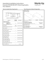
Conguration Specications:
DUPLEX Circuit Markings
• C1000: All Duplexes are common as Single Circuit and marked with Numeral “I” next to each receptacle
• C1200: All Duplexes are Common as Dual Circuit and Marked with One (1) Receptacle as Numeral “I” and one Receptacle as
Numeral “II”
• C1234: All Duplexes are unique with the rst Dual Circuit Duplex marked with One (1) Receptacle as Numeral “I” and one Receptacle as
Numeral “II” and the second Dual Circuit Duplex with One (1) Receptacle as Numeral “III” and one Receptacle as Numeral “IIII”
Circuit Congurations, Duplex Quantities, Power Track Limits:
• On the LOS3-PT3204-CXXXX-XX, install two (2) each, 2 Duplex/2 Outlet receptacles for a total of four (4) 120 V 60 Hz 20 A
receptacles per assembly are installed per Power Track
○ MODEL # LOS3-PT3204-C1000-XX—DO NOT EXCEED TWO (2) CIRCUIT I DUPLEXES PER POWER TRACK AND EIGHT (8) TOTAL
DUPLEXES/FOUR (4) POWER TRACKS PER SYSTEM FOR A TOTAL OF 16 MAXIMUM INDIVIDUAL RECEPTACLES
○ MODEL #LOS3-PT3204-C1200—DO NOT EXCEED TWO (2) CIRCUIT I/II DUPLEXES PER POWER TRACK AND SIXTEEN (16)
TOTAL DUPLEXES/EIGHT (8) POWER TRACKS PER SYSTEM FOR A TOTAL OF 32 MAXIMUM INDIVIDUAL RECEPTACLES
○ MODEL #LOS3-PT3204-C1234—DO NOT EXCEED ONE (1) CIRCUIT I/II DUPLEX AND ONE (1) CIRCUIT III/IIII PER POWER TRACK,
SIXTEEN (16) CIRCUIT I/II and SIXTEEN (16) CIRCUIT III/IIII FOR A TOTAL OF THIRTY-TWO (32) TOTAL DUPLEXES/SIXTEEN (16)
POWER TRACKS PER SYSTEM FOR A TOTAL OF 64 MAXIMUM INDIVIDUAL RECEPTACLES
• On the LOS3-PT3208-CXXXX-XX, install four (4) each, 2 Duplex/2 Outlet receptacles for a total of eight (8) 120 V 60 Hz 20 A
receptacles per assembly are installed per Power Track
○ MODEL # LOS3-PT3208-C1000-XX—DO NOT EXCEED FOUR (4) CIRCUIT I DUPLEXES PER POWER TRACK AND EIGHT (8)
TOTAL DUPLEXES/TWO (2) POWER TRACKS PER SYSTEM FOR A TOTAL OF 16 MAXIMUM INDIVIDUAL RECEPTACLES
○ MODEL #LOS3-PT3208-C1200—DO NOT EXCEED FOUR (4) CIRCUIT I/II DUPLEXES PER POWER TRACK AND SIXTEEN (16)
TOTAL DUPLEXES/FOUR (4) POWER TRACKS PER SYSTEM FOR A TOTAL OF 32 MAXIMUM INDIVIDUAL RECEPTACLES
○ MODEL #LOS3-PT3204-C1234—DO NOT EXCEED ONE (1) CIRCUIT I/II DUPLEX AND ONE (1) CIRCUIT III/IIII PER POWER
TRACK, SIXTEEN (16) CIRCUIT I/II and SIXTEEN (16) CIRCUIT III/IIII FOR A TOTAL OF THIRTY-TWO (32) TOTAL DUPLEXES/EIGHT
(8) POWER TRACKS PER SYSTEM FOR A TOTAL OF 64 MAXIMUM INDIVIDUAL RECEPTACLES
LOS3-PT3204-CXXXX-XX
LOS3-PT3208-CXXXX-XX

Workrite Ergonomics | 800.959.9675 www.workriteergo.com 3 of 6
Snap in two (2) Duplex Receptacles (B) for models
#3204 or four (4) Duplex Receptacles (B) as shown
based on the conguration diagram on Page 2 into the
Power Track (A) as shown
SNAP IN POWER RECEPTACLES
1.1
2.2
2.3
1
The Mounting Brackets and Clips have a right and left
assembly using universal parts. Assemble the Left Bracket
Set using the Left Bracket view as shown using one (1)
Mounting Bracket (C) and one (1) Mounting Clip (D) as
shown
Insert one (1) #10-32 × ½" Phillips Head Screw (E) trough
the Mounting Bracket C) and the Mounting Clip (D) and
install one (1) #10-32 Star Washer Lock Nut (F) and tighten
securely using your #2 Phillips Head Screw Driver and ⅜"
Hex Wrench
Assemble the Right Bracket Set by repeating Steps 2.1 and
2.2 using the Right Bracket View as shown
Note: Pay close attention to the shape of the Mounting
Clips(D) and direction they face as well as the position and
orientation of the Mounting Bracket (C) for proper right- and
left-hand assembly orientation
ASSEMBLE MOUNTING BRACKETS AND MOUNTING CLIPS
2.1
2
D #10-32 × ½" Phillips
Head Screw
Hardware at actual size
B
A
E
E
C
C
D
D
F
F
D
2.1 2.2
2.3
Left Stopper Right Stopper
Left Stopper Right Stopper
If 4 receptacles
If 2 receptacles
Note slope
Side of chassisSide of chassis Power Track
mounts between
Left Clip Right Clip D

4 of 6 Workrite Ergonomics | 800.959.9675 www.workriteergo.com
INSTALL THE LEFT AND RIGHT POWER TRACK BRACKET ASSEMBLIES
DETERMINE POWER ENTRY DIRECTION AND SNAP IN POWER TRACK ASSEMBLIES
3
4
Install the Left Bracket Assembly to the LOS Chassis with
one (1) #10 × ¾" Phillips Head Screw (G) as shown
Install the Right Bracket Assembly to the LOS Chassis with
one (1) #10 × ¾" Phillips Head Screw (G) as shown
Repeat as necessary for as many units as required
The Power Track can be assembled to exit to the right or
left of the LOS unit buy simply ipping over the
Power Track to locate the Power Entry connection to
the correct direction
Once the proper direction is determined for the track snap
the Power Track assembly with receptacles into the Mount
Assemblies as shown
Repeat as necessary for as many units as required
3.1
4.1
3.2
4.2
3.3
4.3
3.1
3.2
4.1
4.2
Shown as Right
Power Entry
Connection
Shown as Le
Power Entry
Connection
G #10 × ¾" Phillips Head
Screw
Hardware at actual size

Workrite Ergonomics | 800.959.9675 www.workriteergo.com 5 of 6
CONNECT JUMPER CABLES
5
Arrange the LOS units in rows and connect Ganging Brackets
#LOS3-STGANGBRKT-B between adjacent stations
With the Lock-Latch open align the rst Jumper Cable (H) male
end to the rst Power Track opposite the Power Entry end of
the Power Track and push in and snap the cable into place
Press the Lock-Latch in as shown to lock the connection
Run the Jumper Cable (H) from the rst unit to the second unit
trough the cable ports in the end of the LOS unit
In the second LOS unit, align the female end of the Jumper
Cable (H) to the spades in the end of the Power Track. With the
Lock-Latch open push the end of the Power Entry Cable in and
onto the spade connectors until the cable snaps into place in
the second LOS unit
5.1
5.2
5.3
5.4
5.5
5.6
5.7
Press the Lock-Latch in as shown to lock the connection
Repeat as required for the row of LOS units to be powered
CAUTION: Do not exceed the recommended amount of receptacle
per circuit by connection to many power tracks in series above the
total Power Track system receptacle recommendations
5.1
5.2
5.3
5.4 5.5
H
Male end of
Jumper Cable
Female end of
Jumper Cable
Snap

6 of 6 Workrite Ergonomics | 800.959.9675 www.workriteergo.com
1500560 Rev A
Determine the number of circuits required to power the Power
Track based on the circuits required.
With all circuit breakers in the “OFF” state position, properly
electrically connect the electrical circuits to the Power In-feed
#LOS-PWRIN-LT72 as shown on the wiring diagram schematic
shown following National Electrical Code and Local Electrical Codes
Align the end of the Power Entry lead #LOS-PWRIN-LT72
to the Spade Connectors on the rst Power Track
With the Lock-Latch open, push the end of the Power Entry
Cable in and onto the spade connectors until the cable
snaps into place
Press the Lock-Latch in as shown to lock the connection
Turn the Source Power Circuit Breakers “ON”
Test the live circuits with proper test equipment to ensure
power is live and properly and correctly connected
CONNECT POWER ENTRY TO SOURCE POWER
See note on using a qualied electrician for this step!
CONNECT POWER ENTRY TO POWER TRACK SYSTEM
6.1
7.1
6.2
7.2
7.3
7.4
7.5
6.3
6.4
6
7
Test the wiring continuity to ensure proper connection
DO NOT TURN SOURCE POWER CIRCUIT BREAKERS
ON UNTIL THE END OF STEP 7
7.1
7.2
7.3
Utility
Circuit 1 (Red)
Circuit 2 (Black)
Neutral (White)
Ground (Green)
Computer
Isolated Circuit 3 (Blue)
Isolated Circuit 4 (Orange)
Isolated Neutral (Grey/White)
Isolated Ground (Green/Yellow)
Black circuit Line
Any phase except Line
Green utility ground for or
Red circuit Line
Any phase except
White neutral for or
Mulitwire branch circuit
Gray neutral for or
Mulitwire branch circuit
Orange circuit Line
Any phase except Line
Blue circuit Line Isolated
Any phase except Line
Green/Yellow ground for or
120/208 Volt WYE Three Phase
Solid lines above
120/240 Volt Single Phase or
Uninterrupted Power Supply
Dashed lines below
Notes:
1. You must only use one power entry
per set of daisy-chained Power Tracks.
2. Phase selection in diagram is for ease
of illustration versus balance.
3. If duplex receptacles split circuits
tapped, failure to energize any line may
result in only half of certain devices
being energized.
4. Multiwire branch circuits require
opposing phases to prevent overload of
shared neutrals.
5. A grounded neutral transformer is
manditory. Load balance is uncertain.
6. Provide neutrals and grounds even if
lines are unused or commoned.
Eight Wire, Four Circuit Power System Wiring Diagram
Two utility circuits plus two computer circuits:
Duplex wiring Typical of 2+2 Planning
Close-up of
successful
connection
/