Page is loading ...

1 of 2 Workrite Ergonomics | 800.959.9675 | www.workriteergo.com
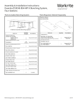
Assembled Line of Sight Chassis with Worksurface
A Line of Sight Power Bar
Qty: 1 B Power Bar Bracket
Qty: 2 C #10-24 ×¾" Phillips Head
Machine Screw
Qty: 2
Required, Sold Separately
Parts Included
IMPORTANT NOTE: Power Bar must be connected to only
one 120 V, 60 Hz, 20 A power source. The user is responsible for
calculating and managing total power load. Failure to follow
these warnings may overload the system and cause circuit
breaker protection to shut down the power system.
Assembly Instructions: Line of Sight Power Bar
LOS3-MM024-4-6 / LOS3-MM024-4-24
D #10-¾" Phillips Pan Head
Sheet Metal Screws
Qty: 2
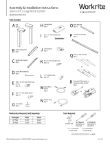
✓ Verify That You Have All The Tools Needed For The Assembly
You will need the following tools:
Drill/driver or Phillips screwdriver with #2 tip
" open ended wrench
1 Remove Front, Rear Panels & Grommet Cover
1.1 If not already removed, remove the Front and
Rear Panels by turning the Panel Locks a quarter
turn towards the center of the panel (inward),
then pivot the panels forward to remove.
If you have Locking Panels, unlock using the
included key.
1.2 Remove the Side or Rear Grommet Covers to
route power in the desired direction.
2 Attach Brackets to Power Bar
Attach the two Power Bar Brackets (B) to the back of the
Power Bar (A) using the two #10-24 ×¾" Phillips Head
Machine Screws (C).
ELECTRICAL RATING: 120 V, 60 Hz, 15 A
8 outlet, 6' cord, or 24' cord
A
C
B
1.1
1.1
1.2
C #10-24 ×¾" Phillips
Head Machine Screw
Hardware at actual size
Front
Panel
Panel
Lock
Rear
Panel

2 of 2 Workrite Ergonomics | 800.959.9675 | www.workriteergo.com
#1500386 Rev B
3 Attach Bracket Assembly to Chassis
3.1 Attach the Bracket Assembly to the mounting holes on the inside
front of the Chassis using the two #10-¾" Phillips Head Sheet
Metal Screws (D).
3.2 Route the cable through the grommet hole heading in the
desired direction.
4 Route Power through Work Centers
4.1 Route each Power Bar cable from
Work Center to Power Source through
the desired grommet holes.
Note: Side to side configurations
(shown) typically will use the
side grommets and back to back
configurations typically will use the
rear grommets.
4.2 Connect all Power Bar plugs to the
Power Source.
4.3 Do not connect Power Bar
to Power Bar.
5 Energize & Test Circuit(s)
Test to confirm all circuits are properly connected and energized.
D
Route cable
through
grommet hole
D #10-¾" Phillips Pan Head
Sheet Metal Screws
Hardware at actual size
View from behind with Monitor
Li removed for clarity
4.1
4.1
/