Page is loading ...

riteBEAM
Power Beam Assembly Instructions
Workrite Ergonomics | 800.959.9675 www.workriteergo.com

Power Beam Assembly Instructions
CAUTIONS AND WARNINGS
WARNING: FAILURE TO FOLLOW CAUTIONS AND WARNINGS BELOW COULD RESULT IN ELECTRICAL SHOCK,
FIRE, PROPERTY DAMAGE, PERSONAL INJURY, OR DEATH.
CAUTIONS:
Read Instructions: Read all warnings and installation instructions before installing and use
Retain Instructions: Retain this instruction sheet for future use
Wet Environment: This system is designed for use indoors in a dry environment
Never use this system in a wet environment
Never allow liquids of any type to spill into the electrical system
Follow Warnings: Read and follow all warnings and directions in this instruction sheet and marked on the components of
the system
Service: There are no serviceable parts contained in this system
Do not open and or modify any parts used in this electrical system
WARNINGS:
Risk of fire or electrical shock: Do not electrically connect to more than one source of power supply
Always verify the electrical system is only connected to one and only one source of power supply
Power Entry Cable: Route the Power Entry Cable where it will not be stepped on, pinched, have devices placed on it, or
become a tripping hazard
Never allow Power Entry Cable to sit in any liquid or get wet in any manner
Location: This system is intended for use indoors in a dry environment only
SYSTEM DESCRIPTION AND REQUIREMENTS: riteBEAM POWER BEAM POWER SYSTEM
Limits & Restrictions:
Eight wire system designed to operate using 4 dedicated 120 V, 60 Hz, 20 A circuits
Power Duplexes oered in Circuit a, b, c, & d
Total Duplexes per dedicated circuit not to exceed 8 total duplexes (Maximum Eight each Circuit a, b, c, & d)
Assembly
All assembly must be completed as outlined in the assembly instructions. All system parts must be used as supplied with no
alterations or modifications
Connection/Power Entry
Power Connection for power entry options oered with this daisy chain power system must be connected by a commercial
Electrician
2 of 10
Workrite Ergonomics | 800.959.9675 www.workriteergo.com

Power Beam Assembly Instructions
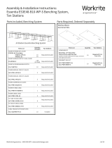
Beam Configurations and Circuit guidelines
Single Circuit
• US Single Circuit – One (1) dedicated circuit only - Use all same receptacle “a” (Not Title 24 compliant)
• Max eight (8) duplexes 20A 120V US NEC – Eight (8) total duplexes / Maximum four (4) seats
• Must use two (2) “a” duplexes per seat
• Four (4) beams Max - single side power configuration
• Two (2) beams Max - back to back power configuration
CANADIAN Single Circuit – One (1) dedicated circuit only - Use all same receptacle “a” (Not Title 24 compliant)
• Max Six (6) Duplexes 15A 120V CSA – Six (6) total duplexes / Maximum three (3) seats
• Must use two (2) “a” duplexes per seat
• Three (3) beams Max -single side power configuration
• One (1) beam Max – back to back power configuration
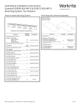
Dual Circuit NON-TITLE24
US Dual Circuit – Use two (2) dedicated circuits only – Use two (2) receptacles “a” & “c Δ”
• Max eight (8) duplexes per circuit 20A 120V US NEC – Sixteen (16) total duplexes / Maximum Eight (8) seats
• Must use one (1) “a” and one (1) “c Δ” duplex per seat
• Eight (8) beams Max - single side power configuration
• Four (4) beams Max - back to back power configuration
CANADIAN Dual Circuit – Use two (2) dedicated circuits only – Use two (2) receptacles “a” & “c Δ”
• Max six (6) Duplexes per circuit 15A 120V CSA – Twelve (12) total duplexes / Maximum six (6) seats
• Must use one (1) “a” and one (1) “c Δ” duplex per seat
• Six (6) beams Max -single side power configuration
• Three (3) beams Max – back to back power configuration
Dual Circuit TITLE24
US Dual Circuit – Use two (2) dedicated circuits only – Use two (2) receptacles “a” & “T24 c Δ”
• Max eight (8) duplexes per circuit 20A 120V US NEC – Sixteen (16) total duplexes/ Max Eight (8) Seats
• Must use one (1) “a” and one (1) “T24 c Δ” duplex per seat
• Eight (8) beams Max - single side power configuration
• Four (4) beams Max - back to back power configuration
CANADIAN Dual Circuit – Use two (2) dedicated circuits only – Use two (2) receptacles “a” & “T24 c Δ”
• Max six (6) Duplexes per circuit 15A 120V CSA – Twelve (12) total duplexes / Maximum six (6) seats
• Must use one (1) “a” and one (1) “T24 c Δ” duplex per seat
• Six (6) beams Max -single side power configuration
• Three (3) beams Max – back to back power configuration
3 of 10
Workrite Ergonomics | 800.959.9675 www.workriteergo.com

Power Beam Assembly Instructions
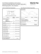
Quad Circuit NON-TITLE24
• US Quad Circuit – Use four (4) dedicated circuits only – Use all four (4) receptacle options “a”, “b”, “c Δ” & “d Δ”
• Max eight (8) duplexes per circuit 20A 120V US NEC – Thirty two (32) total duplexes/ Maximum Sixteen (16) seats
• Must use one (1) “a” and 1 “c Δ” duplex for eight (8) seats and one (1) “b” and one (1) “d Δ” for the remaining eight
(8) seats
• Sixteen (16) beams Max - single side power configuration
• Eight (8) beams Max - back to back power configuration
CANADIAN Quad Circuit – Use Four (4) dedicated circuits only – Use all four (4) receptacle options “a”, “b”, “c Δ” & “d
Δ”
• Max six (6) Duplexes per circuit 15A 120V CSA– Twenty four (2)4 total duplexes / Maximum twelve (12) seats
• Must use one (1) “a” and one (1) “c” duplex for six (6) seats and one (1) “b” and one (1) “d” for the remaining six (6)
seats
• Twelve (12) beams Max - single side power configuration
• Six (6) beams Max - back to back power configuration
Quad Circuit TITLE24
US Quad Circuit – Use four (4) dedicated circuits only – Use all four (4) receptacle options “a”, “b”, “T24 c Δ” & “T24 d
Δ”
• Max eight (8) duplexes per circuit 20A 120V US NEC – thirty two (32) total duplexes/ Maximum sixteen (16) seats
• Must use one (1) “a” and one (1) “T24 c” duplex for 8 seats and 1 “b” and 1 “T24 d” for the remaining eight (8)
seats
• Sixteen (16) beams Max - single side power configuration
• Eight (8) beams Max - back to back power configuration
CANADIAN Quad Circuit – Use Four (4) dedicated circuits only – Use all four (4) receptacle options “a”, “b”, “T24 c Δ” &
“T24 d Δ”
• Max six (6) Duplexes per circuit 15A 120V – 24 total duplexes / Maximum twelve (12) seats
• Must use one (1) “a” and one (1) “T24 c Δ” duplex for six (6) seats and one (1) “b” and one (1) “T24 d Δ” for the
remaining six (6) seats
• Twelve (12) beams Max - single side power configuration
• Six (6) beams Max - back to back power configuration
4 of 10
Workrite Ergonomics | 800.959.9675 www.workriteergo.com

Power Beam Assembly Instructions
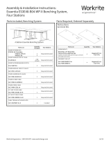
INCLUDES ALLEN KEY, OUTLET COVERS &
HARDWARE (PACKED INSIDE BEAM)
5 of 10
Workrite Ergonomics | 800.959.9675 www.workriteergo.com
PB-PWRIN-72-X
POWER IN CABLE, 8 WIRE
PB-JUMPER-21
FESTOON CABLE
PB-ISO-DUPLEX-C-X
PB-ISO-DUPLEX-D-X
ISO RECEPTACLE
PB-ISO-T24-DUPLEX-C-X
PB-ISO-T24-DUPLEX-D-X
CONTROLLED RECEPTACLE
PB-STD-DUPLEX-A-X
PB-STD-DUPLEX-B-X
STANDARD RECEPTACLE
PB-DIVMNT20-KIT-X
PB-DIVMNT26-KIT-X
KIT INCLUDES:
SPACERS (X2)
BOLT (X4)
PB-FOOTKIT-X
KIT INCLUDES:
FOUR (4) BOLTS FOR ASSEMBLY
PB-LEG-4W-X
KIT INCLUDES:
SIDE COVER (X3)
TOP CAP
BLIND INLET COVER AND
BOLTS
PB-48BEAM-XX
PB-60BEAM-XX
PB-72BEAM-XX
PB-PPOLE-4W-X
POWER POLE
PB-PWRIN-144
CEILING POWER IN CABLE, 8 WIRE
PB-PWRIN-LT72-X
POWER IN CABLE, 8 WIRE, GREY LIQUID TIGHT

Power Beam Assembly Instructions
Optional Privacy Panel Rail Installation
Remove top cap and front and rear panels from beam and set aside before beam assembly.
If you have chosen to use the Power Beam Divider Panels install the divider mount posts as
shown and secure with M8 x 1.25P x 12mm long Allen Cap Screws.
Repeat for additional beams.
Assemble the foot to the leg or power pole and secure with 4 each M8 x 1.25P x 12mm long Allen Cap Screws.
Repeat for additional legs.
If required remove the upper beam connection point cover from the leg or power pole and foot assembly where
the beam will be connected.
Install 1 each M8 x 1.25P x 12mm long Allen Cap Screw into the lower bolt hole in the leg/power pole and foot
assembly.
Leave bolt loose by ¼” to allow beam keyhole to slide onto leg.
Place the beam into place in the slots and onto the pre-installed screw of the leg.
Install 1 each M8 x 1.25P x 12mm long Allen Cap Screw into the upper bolt hole in the leg and tighten securely.
Tighten the lower Allen Cap Screw securely.
Repeat for additional leg assemblies.
Foot and leg/power pole assembly
Leg/Power Pole and beam assembly
6 of 10
Workrite Ergonomics | 800.959.9675 www.workriteergo.com

Power Beam Assembly Instructions
Multi-beam congurations
Other than the first beam all beams are electrically connected together with the festoon cable.
Install the festoon cable from the first beam to the next beam by sliding the festoon cable into
place between each beam. Connect the festoon aligning the end to the power rail in the bean and
snap into place. Connect the other end for the festoon by repeating this step.
Repeat to connect each additional beam.
Note – Connect ONLY ONE festoon cable from beam to beam.
Slide receptacle in direction of arrow to lock in place.
Receptacle installation
Insert the receptacle into the slot.
7 of 10
Workrite Ergonomics | 800.959.9675 www.workriteergo.com

Power Beam Assembly Instructions
Power entry cable installation
Remove the solid cover cap at the bottom of the leg.
Insert the power entry cable into the upper hole of the leg routing the cable down the leg and
out the access hole in the bottom of the leg.
Install the cable exit cover to the leg with 2 each M8 x 1.25P x 12mm long Allen Cap Screws.
Note – Connect ONLY ONE Power entry cable into the beam assembly.
Note – Connection to live power must be done by a commercial electrician.
Workrite Ergonomics | 800.959.9675 www.workriteergo.com
8 of 10
Ceiling feed power entry cable installation
Insert the ceiling power entry cable into power pole routing the cable down the pole and into
the beam.
Note – Connect ONLY ONE Power entry cable into the beam assembly.
Note – Connection to live power must be done by a commercial electrician.

Power Beam Assembly Instructions
Power Pole assembly
Workrite Ergonomics | 800.959.9675 www.workriteergo.com
9 of 10
Insert the power pole upper section on to the power pole leg (The power feed cable must be
fed into the upper pole section prior to assembly).
Install M4 x10mm screws (x4) to secure the upper pole.

Workrite Ergonomics | 800.959.9675 www.workriteergo.com
10 of 10
Final Assembly steps
If you are installing network cabling now is the time to install all the network cables and receptacles.
Install front and back covers placing the bottom edge of the cover into the bottom slot of the beam and
tip into place.
Holding the front and back covers in place set the top cover over the divider posts and onto the beam
over the front and back cover.
Optional Privacy Panel
Slide the spacers onto privacy panel rails prior to installing the privacy panel.
Power Beam Assembly Instructions
Power Beam Wiring Diagram
/