Page is loading ...

Workrite Ergonomics | 800.959.9675 www.workriteergo.com 1 of 6
or
Assembly & Installation Instructions:
Line of Sight ADA Electric, Single User
LOS3-B-AH11-XX-X
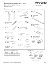
Parts Included
Tools Required
4 mm Allen wrench
#2 Phillips screwdriver or
drill/driver with #2 tip
SAVE THESE INSTRUCTIONS
WARNING: Maximum equipment loading of table assembly in addition to specied top is as follows:
■ Maximum top load: 120 lb (54.4 kg)
■ Maximum monitor lift load (each): 40 lb (18.2 kg)
Loading should be evenly distributed over table surfaces.
ELECTRICAL RATINGS:
Monitor Li System Electrical Rating: 100/240 VAC, 50/60 Hz /1.6 A
Table Li System Electrical Rating: 120 VAC, 60 Hz, 4 A
Power Bar Electrical Rating (Optional): Models LOS3-MM024-4-XX
120 VAC, 60 Hz, 15 A : LR55351
FLAMMABILITY: All worksurfaces used must meet UL 962 ammability requirements
■ Flame Spread Rating maximum 200
■ Smoke Developed Index maximum 450
IMPORTANT SAFETY INSTRUCTIONS:
When using an electrical furnishing, basic precautions should always be followed, including the following:
Read all instructions before using this Line of Sight Education and Training Work Center.
DANGER: To reduce the risk of electric shock, always unplug this Line of Sight Education and Training Work Center from the electrical
outlet before cleaning or servicing.
WARNING: To reduce the risk of burns, re, electric shock, or injury to persons:
1. Unplug from outlet before putting on or taking off parts.
2. Close supervision is necessary when this furnishing is used by, or near children, invalids, or disabled persons.
3. Use this furnishing only for its intended use as described in these instructions, do not use attachments not
recommended by the manufacturer.
Note: The Line of Sight ADA
Electric Work Center Chassis
comes preassembled.
A Line of Sight ADA
Electric Work Center
Qty: 1 B Quick Release
Monitor Adapter Kit
Qty: 1
D
Wire Loom, 1" × 2'
Qty: 1
C Cable Ties
Qty: 5
36" model shown

2 of 6 Workrite Ergonomics | 800.959.9675 www.workriteergo.com
Polarized Plug Instructions (Only applicable to products having a polarized plug power cord):
Some products include a polarized plug—see Figure A (One A/C plug blade wider than the other)—to reduce the risk of
electrical shock. A polarized plug only ts a polarized power outlet one way. If the polarized plug does not t properly into the
electrical outlet turn the power plug over to see if it then ts properly and fully into the outlet. If the plug does still does not t
the outlet, contact a certied electrician to install the correct matching polarized electrical outlet.
Caution: Never modify the power cord plug in any way
Double-Insulated Products Instructions:
Some products are double-insulated. No means of grounding is required or provided on a double-insulated product; nor is a
means for grounding to be added to the product. The plug in a double insulated system is shown in Figure A. Double-insulated
products are indicated with markings of “double-insulated” or the “double box symbol” or both.
Grounding Instructions (For grounded electric products only):
Products with grounded power cords are for use on a nominal 120 V circuit and has a grounded plug as shown in Figure B
Make sure the product is connected to an electrical outlet having the same conguration as the plug shown in Figure C.
Caution: Never modify, remove, or use adapters that eliminate the ground connections from the grounded power cord
A/C Power:
Products sold in North America and other regions are 120 V A/C as marked on the power supply/control box of the furnishing
and are to be used on a normal 120 V A/C circuit. Always follow the instructions above for power connection using grounded or
double insulated power cords as supplied.
• Only use power cord(s) supplied with your electric product
• Never modify, alter, use an adapter, or change the electrical system of this product in any way.
Warning: Doing so may cause risk of electrical shock or re
Illustration Disclaimer—Power Plug and Receptacle Images:
In some cases, the images in this instruction may not match the power cord supplied with your electrical furnishing based on your region.
Plug type, blade size, and shape may change.
Grounding Pin
Figure B
Grounded Outlet
Figure C
Polarized Plug
Figure A
4. Never operate this furnishing if it has a damaged cord or plug, is not working properly, has been dropped or
damaged, or dropped into water. Return the furnishing to a service center for examination and repair.
5. Keep the cord away from heated surfaces.
6. Never operate the furnishing with the air openings blocked. Keep the air openings free of lint, hair, and the like.
7. Never drop or insert any object into any opening.
8. Do not use outdoors.
9. To disconnect, remove plug from outlet.
10. Mount only approved work surfaces and secondary surfaces (shelves) in accordance with instructions. Failure to
do so may cause instability, collapse, or failure of electrical components.

Workrite Ergonomics | 800.959.9675 www.workriteergo.com 3 of 6
Monitor Lift
Switch
INSTALL QUICK RELEASE MONITOR ADAPTER
Note: You will need to mount the monitor in order to determine the correct installation height.
Remove the monitor from the factory mount, if necessary, and retain the screws that came with
the monitor
Attach Quick Release Monitor Adapter (B) to the back of your VESA compatible Monitor
Note: Use the screws (and spacers) that best fasten your monitor to the Adapter. These may be
the original monitor screws, or one of the three lengths included with the Quick Release Adapter
hardware kit. Many monitors (Dell) have a recessed mount where the spacers will be required
Note: You can install the monitor directly on the Monitor Lift VESA plate and NOT use the Quick
Release Adapter if security is an issue. This makes it more difcult (but not impossible) to remove
the monitors quickly
2
2.1
B
X
X
.25"
≤ .25"
X
X
.25"
≤ .25"
X
.25
X
X
.25"
≤ .25"
SET MONITOR HEIGHT
Measure and note the distance from the top of the Quick
Release Adapter to the top of the monitor ("X")
Remove the Monitor Lift VESA Plate by removing the two
athead screws with the 4 mm Allen wrench
Reposition so that when installed, the monitor is at least .25"
below the Monitor Lift top
X +.25" = installation height
Reattach using the two athead
screws with the 4 mm Allen wrench
3.1
3.4
3.3
Monitor top
Monitor
Quick Release top
Back view
Side view
Installed
3.2
3.5
3.3
Monitor Lift
Monitor Lift Monitor Lift
VESA Mount
Plate
Remove
Replace
Flathead
screws
3
3.1
3.2
3.3
3.4
3.5
B
CONNECT POWER & RAISE MONITOR LIFT
1.1
1.2
1
Detach the Power Cord taped to side of Chassis and
temporarily route the cord from the Power Supply and
plug into power.
Press and hold the Monitor Lift Up Switch button to
raise the Monitor Lift, opening the Monitor Bay Lid as it
rises. Raise to highest position and release the button.
A
1.2
1.1
2.1

4 of 6 Workrite Ergonomics | 800.959.9675 www.workriteergo.com
INSTALL MONITOR
4
4.1 Slide the Quick Release Monitor Adapter onto the VESA mount
IMPORTANT: Conrm that the Monitor Lift raises the Monitor
Lid and not the monitor! You will want to test the Monitor Arm
travel to conrm Monitor Bay Lid function properly and anticipate
cabling around the monitor lift before proceeding to power and
technology installation.
4.1
INSTALL POWER BAR OPTIONS FOR YOUR CONFIGURATION
If you did not purchase the Power Bar, skip to Step 6
Note: Power Track is not compatible with the ADA Work Centers
With the Work Center built, you will now need to add your power options for your specic conguration. Follow the instructions that came
with the Power Bar to complete your conguration
5
INSTALL OPTIONAL ACCESSORIES FOR YOUR CONFIGURATION
INSTALL TECHNOLOGY FOR YOUR CONFIGURATION
6
7
With the monitors and power components installed, you will now need to add your optional accessories like Worksurface Grommets,
Remote Controls and CPU Holders. Follow the instructions with the Optional Accessories to complete this step
With all Line of Sight components installed, you will now need to install all the technology components to complete your system. Install
all computers, peripherals like keyboards and mice, and network cabling to complete your installation according to the manufacturers
specications and your specic application

Workrite Ergonomics | 800.959.9675 www.workriteergo.com 5 of 6
MANAGE CABLING
8
D
C
With monitors and technology installed, you'll want to start
considering all the cabling requirements
Note: It is critical that no wires interfere with the travel of the
Monitor Lift. Use Cable Ties (C) to fasten all cabling securely
out of the way of all moving Monitor Lift components
Use the Wire Loom (D) to manage all user cables routing from
the keyboard tray to the CPU. This may include keyboard,
mouse, monitor and data cables
Keyboard tray
cable access
Inside Chassis
To CPU
Monitor Lift
ASSEMBLE FINAL ROOM CONFIGURATION & CONNECT TO POWER SOURCE
9
With all individual Work Centers built and electrical installed, arrange Work Centers according to your nal
room conguration. You will need at least two people to move a Work Center. Adjust the Glides on the bottom of the
feet to assure each Work Center is level and stable in its nal location
Note: ADA Work Centers must be installed at the end of rows or freestanding for access and power compliance. It is
critical that you follow all warnings and cautions when you get to nal assembly. Consult the instructions that came
with your electrical components and follow all cautions and warnings carefully!
Final assembly will include testing of electrical components and functioning of all Monitor Lifts
INSTALL BATTERIES IN POWER SUPPLY FOR BATTERY BACKUP (OPTIONAL)
10
With all technology installed, cables routed and fastened and
the system connected to constant power, add two 9 V batteries
to the Power Supply for Battery Backup. In the event of a power
outage, the battery backup will allow 2–3 emergency closures to
stow the technology
Important: The Power Supply MUST be plugged into a
“constant on” power circuit or the batteries will discharge!
Replace batteries once a year
Power Supply, Bottom
Rear of Chassis
Battery location

Workrite Ergonomics | 800.959.9675 www.workriteergo.com 6 of 6
1500490 Rev C
REMOVE PROTECTIVE TAPE & REPLACE FRONT AND REAR PANELS
11
11.1
11.2
Remove the protective tape on the Panels and Chassis
Reattach your front and rear panels. You now have a complete
Work Center. Finish building all Work Centers before proceeding
to nal room assembly
Remove
Front & Rear Panels Chassis
Remove
11.1
11.1
Laminate Worksurfaces:
For everyday cleaning, wipe the surface with a damp cloth or sponge. Use a spray cleaning agent sparingly if necessary (suggested spray
cleaning agents are indicated below). Do not pour water directly onto the worksurface. Wipe completely dry with a soft rag using a straight
line motion
• Worksurfaces may need occasional dusting. To keep the surface in ideal condition, use a non-oily furniture spray
• Difcult stains such as coffee can be removed using a mild cleaning detergent and a soft bristled (non-metallic) brush. Do not scrub
surfaces with too much force, otherwise the surface could lose its nish
• Stubborn stains that resist any of the above cleaning methods may require the use of undiluted household bleach. Apply a very small
amount of bleach (approximately ¼-capful) to the stain and let stand no longer than two minutes. Rinse thoroughly with warm water and
wipe dry. WARNING: Prolonged exposure of the laminate surface with bleach will cause discoloration
• Ensure to always rinse laminate surfaces after cleaning. Even a small amount of cleaning residue can result in permanent discolorations
• Recommended Laminate Worksurface cleaning agents:
• Non-abrasive spray cleaning agents: Dawn, Fantastik, Windex, Lysol
• Furniture spray: Pledge
• Stain removers: Lestoil, Clorox
Painted steel parts:
• Clean surfaces regularly with damp cloth
• If necessary, use a spray cleaning agent (e.g. Fantastik) sparingly. Wipe completely dry with a soft rag using a straight line motion
• Lightly brush both vertical and horizontal surfaces to prevent dust build-up
Polished chrome feet:
• The feet can be polished when they become dull with Aluminum polish (e.g. Flitz or Mothers Mag Polish) with special attention to keep
polish from painted surfaces. Follow manufacturers instructions for best results
CLEANING INSTRUCTIONS
✓
/