Page is loading ...

Workrite Ergonomics | 800.959.9675 www.workriteergo.com 1 of 4
8 mm
#2 Drive
8 mm
4 mm
3.2 mm
M4 x 0.7 mm Thread
8 mm
#2 Drive
12 mm
4 mm
3.2 mm
M4 x 0.7 mm Thread
8 mm
#2 Drive
18 mm
4 mm
3.2
mm
M4 x 0.7 mm Thread
8 mm
#2 Drive
25 mm
4 mm
3.1 mm
M4 x 0.7 mm Thread
8 mm
#2 Drive
16 mm
4 mm
3.1 mm
M4 x 0.7 mm Thread
8 mm
#2 Drive
10 mm
4 mm
3.1 mm
M4 x 0.7 mm Thread
8 mm
#2 Drive
8 mm
4 mm
3.2 mm
M4 x 0.7 mm Thread
8 mm
#2 Drive
12 mm
4 mm
3.2 mm
M4 x 0.7 mm Thread
8 mm
#2 Drive
18 mm
4 mm
3.2
mm
M4 x 0.7 mm Thread
8 mm
#2 Drive
25 mm
4 mm
3.1 mm
M4 x 0.7 mm Thread
8 mm
#2 Drive
16 mm
4 mm
3.1 mm
M4 x 0.7 mm Thread
8 mm
#2 Drive
10 mm
4 mm
3.1 mm
M4 x 0.7 mm Thread
M8 Flat Head Cap Screw M4 8mm Screw M4 12mm Screw M4 16mm Screw Spacer
Plastic Cap 7/32” Allen Wrench 1/8” Allen Wrench
Button Head Allen Cap ScrewPivot Pin
Steel WasherPlastic Pivot Washer
M8 Flat Head Cap Screw M4 8mm Screw M4 12mm Screw M4 16mm Screw Spacer
Plastic Cap 7/32” Allen Wrench 1/8” Allen Wrench
Button Head Allen Cap ScrewPivot Pin
Steel WasherPlastic Pivot Washer
M8 Flat Head Cap Screw M4 8mm Screw M4 12mm Screw M4 16mm Screw Spacer
Plastic Cap 7/32” Allen Wrench 1/8” Allen Wrench
Button Head Allen Cap ScrewPivot Pin
Steel WasherPlastic Pivot Washer
8 mm
#2 Drive
8 mm
4 mm
3.2 mm
M4 x 0.7 mm Thread
8 mm
#2 Drive
12 mm
4 mm
3.2 mm
M4 x 0.7 mm Thread
8 mm
#2 Drive
18 mm
4 mm
3.2
mm
M4 x 0.7 mm Thread
8 mm
#2 Drive
25 mm
4 mm
3.1 mm
M4 x 0.7 mm Thread
8 mm
#2 Drive
16 mm
4 mm
3.1 mm
M4 x 0.7 mm Thread
8 mm
#2 Drive
10 mm
4 mm
3.1 mm
M4 x 0.7 mm Thread
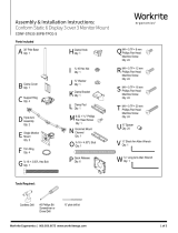
Assembly & Installation Instructions:
Conform LT Dual Monitor Arm
CONF-LT-2SA-TPCG-G
Parts Included
C Clamp Mount
Qty: 1
E ⅜-16 × 3.50"L Hex Bolt
Qty: 1
N ⅜-16 × 2.50"L Button
Head Cap Screw
Qty: 2
H ⅜" Washer
Qty: 1
P ⅜-16 Nylock Nut
Qty: 2
Q ⅜ " Belleville Washer
Qty: 2
R Plastic Washer
Qty: 2
S Cover Cap
Qty: 2
O Pivot Pin
Qty: 2
F Clamp Knob
Qty: 1
G ⅜-16 Hex Nut
Qty: 1
A Monitor Arm
Qty: 2
B Base
Qty: 1
I Clamp Bracket
Qty: 1
D ¼-20×⅜" Flat
Head Screw
Qty: 2
L Grommet Mount
Channel
Qty: 1
J Clamp Pad
Qty: 1
U M4 × 0.7P × 8 mm
Phillips Pan Head
Machine Screw
Qty: 8
V M4 × 0.7P × 12 mm
Phillips Pan Head
Machine Screw
Qty: 8
W
M4 × 0.7P × 18 mm
Phillips Pan Head
Machine Screw
Qty: 8
X
M4 × 0.7P × 20 mm
Phillips Pan Head
Machine Screw
Qty: 8
Y
⅜" Spacer
Qty: 8
Z
3⁄16" Long Arm Allen Wrench
Qty: 1
M ⅜-16 × 4.50"L Stud
Qty: 1
Tools Required:
#2 Phillips
Screwdriver
#3 Phillips
Screwdriver
7⁄16" End Wrench
T Quick Release
Qty: 2
K 6-32 × 5⁄16" Phillips
Pan Head Screw
Qty: 1
CAUTION: The Monitor Arm contains a spring
that when lowered and released, can recoil,
moving upward rapidly potentially causing injury.
Use caution when assembling and mounting the
monitor arm and monitors to avoid this hazard

2 of 4 Workrite Ergonomics | 800.959.9675 www.workriteergo.com
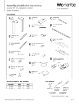
Conform LT
Attach the Clamp Mount (C) to Dual Base (B) with two
(2)¼-20×⅜"FlatHeadScrews(D)usinga#3Phillips
Screwdriver tighten securely
PlacetheClampKnob(F)onthe⅜-16×3.50"LHexBolt(E)
Placethe⅜Washer(H)ontotheHexBolt(E)
Installthe⅜-16HexNut(G)ontotheHexBolt(E)andtighten
to hold the knob in place
Install the Bolt and Knob assembly into the Clamp Bracket (I)
Attach the Clamp Pad (J) to the Hex Bolt (E) with the
6-32 × 5⁄16" Phillips Head Screw (K) and tighten with a #2
Phillips Head Screwdriver as shown
Set the Clamp Bracket Assembly aside
Place Base (B) on the rear edge of your worksurface
From the underside, place the clamp bracket and knob
assembly into the slots of the Base (B). Be sure the bracket is
fully seated and tighten securely
Note: Place the Clamp Bracket Assembly up as high as
possible into the Pole Base to make it easy to tighten
Installthe⅜-16×4.50"LStud(M)intotheBase(B)atleast
8 full turns as shown
Place the Base & Stud into the grommet hole location for
attaching to your desk
Note: If there is no grommet location in your desk you can
drill a hole as small as ⅜" using a power drill and drill bit
or you can use a hole saw and drill a larger hole up to 3"
diameter to install the grommet mount option
From the underside, place the Grommet Mount Channel (L)
onto the Stud (M) with the “U” facing up as shown. Place the
⅜Washer(H)andthe⅜-16HexNut(G)ontotheStud(M)
and tighten securely
ASSEMBLE & MOUNT— CLAMP MOUNT DUAL BASE ASSEMBLY
ASSEMBLE & MOUNT—GROMMET MOUNT BASE ASSEMBLY
1a.1
1b.1
1a.2
1a.3
1a.4
1a.5
1a.6
1a.7
1a.8
1a.9
1b.2
1b.3
1a
1a
1b
E
F
H
G
B
C
B
B
M
I
J
D
K
B
Grommet Hole
1a.2
1a.1
1a.3
1a.4
1a.5
1a.6
1a.8
1b.1
1b.2
1a.9
K 6-32 × 5⁄16" Phillips
Pan Head Screw
Hardware at actual size
L
M
H
G
B
1b.3

Workrite Ergonomics | 800.959.9675 www.workriteergo.com 3 of 4
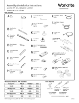
Place the Plastic Washer (R) into the Pivot Pin (O)
PlacetherstPivotPinandPlasticWasherintotherst
Monitor Arm (A)
Align the Monitor Arm (A) and Pivot Pin (O) and Plastic
Washer (R) to the Dual Base (B)
Installone(1)BellevilleWasher(Q)andthe⅜-16×2.50"
Button Head Cap Screw (N) through the Monitor Arm and
Pin assembly into the Dual Base as shown and tighten with
the 3⁄16" Long Allen Wrench (Z)
Note: Do not fully tighten as it will stop the arm for moving
freely and adjusting. Tighten enough to remove free play
and still move easily about the base.
Holdingthe⅜-16×2.50"ButtonHeadCapScrewwiththe
3⁄16" Long Allen Wrench. Attach one (1) ¼-20 Nylock Nut (P)
and tighten securely with a 7⁄16" End Wrench
Install the Cover Cap (S) to the Arm as shown
Repeat Steps 2.1 to 2.6 to attach the second Monitor Arm
(A) to the dual base assembly
ATTACH MONITOR ARM TO BASE
2.1
2.2
2.3
2.4
2.5
2.6
2.7
2
Note: Using the Quick Release Mount is optional. Your
monitor can be attached directly to the VESA plate of the
monitor mount if desired
Locate the VESA Mount Pattern on the back of
your monitor
Note: In some cases, the VESA mounting pattern is hidden
by a removable cover or the monitor base. These must be
removed to install the Quick Release or mount the monitor
Mount the Quick Release (T) to the VESA mount on your
monitor as shown with four (4) M4 Screws either (U), (V),
(W) or (X) and tighten securely
Note: Always use the shortest screws possible to avoid
damaging the display by using screws that are too long
Note: In some case your monitor may require the use of
the ⅜" Spacers (Y) to allow proper installation of the Quick
Release (T)
Align the Monitor with Quick Release onto the VESA Plate
and then slide down to lock in place as shown
ATTACH THE QUICK RELEASE BRACKET & INSTALL THE MONITOR
3.1
3.2
3.3
3
or
Q
N
S
O
P
B
R
A
T
UVWX
Y
3.1
3.3
3.2
2.6
2.1
2.5
2.2
2.3
2.4
Z

4 of 4 Workrite Ergonomics | 800.959.9675 www.workriteergo.com
1500557 Rev A
5 .1
Z
Tension Adjustment
Place monitor cables into the cable retainers on the upper
section of the monitor arm as shown
Snap the cable manager off the lower section of the arm
and place the monitor cables into the arm.
Note: You must leave enough slack in your monitor cables
for the monitor to rotate freely at the top of the arm and
between the upper and lower arm. Failure to do so will limit
the adjustability and movement of the monitor and may
damage the monitor cables
Snap the Lower Cable Manager Cover back onto the lower
arm as shown
Locate the two holes in the cover on the right side of the
upper monitor arm
Too Heavy—If when you raise your monitor and monitor
arm up to the highest position and the monitor drops,
place the 3⁄16"LongAllenWrench(Z)rstintotheupper
adjuster on the right side of the arm and tighten turning
clockwise slightly. Repeat this step on the low adjuster.
Test when done, repeat adjustment as necessary
Too Light—If when you lower your monitor and monitor
arm up to the lowest position and the monitor rises,
place the 3⁄16"LongAllenWrench(Z)rstintotheupper
adjuster on the right side of the arm and tighten turning
clockwise slightly. Repeat this step on the low adjuster.
Test when done, repeat adjustment as necessary
Locate the tilt adjustment bolt on the Monitor Mount
Ifthemonitortiltistoodifculttotiltloosenthetilt
adjustment bolt using the 3⁄16" Long Allen Wrench (Z) until
the monitor is easy to tilt but still holds in position after
adjustments are made (do not over loosen)
If the monitor drops or is not holding tilt, tighten the tilt
adjustment bolt using the 3 ⁄16" Long Allen Wrench (Z) until
the monitor holds tilt but still allows tilt adjustments to be
made easily (do not over tighten)
CABLE MANAGEMENT
ADJUSTING MONITOR ARM TENSION
ADJUSTING MONITOR TILT
4.1
4.2
4.3
5.1
5.2
5.3
6.1
6.2
6.3
4
5
6
Z
Tilt Adjustment Bolt
Grommet mount only
6.1
4.1
4.2 4.3
6.2–6.3
pull
off
snap
back
/