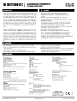
HK Instruments CDT2000 User manual

Type
User manual

This manual is also suitable for

Copyright HK Instruments 2022 www.hkinstruments. Installaon version 9.0 2022
INSTALLATION
INSTRUCTIONS
CARBON DIOXIDE TRANSMITTERS
CDT2000 Series
READ THESE INSTRUCTIONS CAREFULLY BEFORE ATTEMPTING
TO INSTALL, OPERATE OR SERVICE THIS DEVICE.
• Failuretoobservesafetyinformaonandcomplywithinstrucons
canresultinPERSONALINJURY,DEATHAND/ORPROPERTY
DAMAGE.
• Toavoidelectricalshockordamagetoequipment,disconnect
powerbeforeinstallingorservicinganduseonlywiringwith
insulaonratedforfulldeviceoperangvoltage.
• Toavoidpotenalreand/orexplosiondonotuseinpotenally
ammableorexplosiveatmospheres.
• Retaintheseinstruconsforfuturereference.
• Thisproduct,wheninstalled,willbepartofanengineeredsystem
whosespecicaonsandperformancecharacteriscsarenot
designedorcontrolledbyHKInstruments.Reviewapplicaons
andnaonalandlocalcodestoassurethattheinstallaonwill
befunconalandsafe.Useonlyexperiencedandknowledgeable
technicianstoinstallthisdevice.
•Fuseatloadsupply(normally6A,10A,16A)doesnotalwayslimit
therelayoutputloadcurrentto6A.RelayMaximumLoad(250Vx
6Ares.)
•Addanexternalfusetorelaycommonconnector.Useame-lag
 fuse(max6A)thatisinaccordancewiththestandardIEC60127-2.
 Theproductdoesn’thaveaninternalfusefortherelay.
 CAUTION:Theproductmayonlybeconnectedtoovervoltage
 categoryIIelectricitynetworkaccordingtoIEC60664-1.
SPECIFICATIONS
ThankyouforchoosinganHKInstrumentsCDT2000seriescarbon
dioxidetransmier.TheCDT2000seriesisintendedforuseincom-
mercialenvironmentsinHVAC/Rapplicaons.
TheCDT2000seriesmeasurescarbondioxide(CO2),ulizingthein-
dustrystandardNDIRmeasurementprinciple,andtemperature(T).
Oponalrelavehumidity(rH)measurementisalsoavailableinthe
samedevice.Eachmeasurementparameter(CO2,rH,T)hasasepa-
rateeldcongurableoutput.
TheCDT2000seriescarbondioxidetransmiersareavailablewith
Modbusconguraon,relayandtouchscreendisplay.
The CDT2000 series transmiers calibrate themselves automa-
callyusingABCTMlogic.TheABCTMlogicrequiresthatthespacein
which the transmier is used needs to to be unoccupied for four
hoursperdaysothattheindoorCO2concentraondropstotheout-
sidelevel.CDT2000-DCisadualchannelmodelwithameasuring
channelandareferencechannelthatmakesaconnuouscompari-
sonandthenecessaryadjustmentaccordingly.CDT2000-DCisalso
suitableforbuildingsthatareconnuouslyoccupied.
•humidityinvariousindustrialapplicaons
•temperaturesinHVAC/Renvironment
•CDT2000-DCseriesdevicescanalsobeusedinapplicaonswhere
thereisaconstantsourceofcarbondioxidepresent(forexample
hospitalsandgreenhouses)
SPECIFICATIONS
Performance
Measurement ranges:
CO2:400–2000ppm
Temperature:0...50°C
Relavehumidity:0100%
Accuracy:
CO2:±40ppm+3%ofreading,DCmodel:75ppmor
10%ofreading(whicheverisgreater)
Temperature:<0.5ºC
Relavehumidity:±2...3%at0...50°Cand10–90%rH
Totalerrorbandincludesaccuracy,hysteresisand
temperatureeectover5...50°Cand10–90%rH.
Technical Specicaons
Media compability:
Dryairornon-aggressivegases
Measuring units:
ppm,°Cand%rH
Measuring element:
CO2:Non-dispersiveinfrared(NDIR)
Temperature: Pt1000(modelswithoutrH-measurement
 Integrated(modelswithrH-measurement)
Relavehumidity:Thermosetpolymercapacive
sensingelement
Calibraon:
Automacself-calibraonABCLogicTMorconnuous
comparison(DC)
Environment:
Operangtemperature:0...50°C
Storagetemperature:-20...70°C
Humidity:0to95%rH,noncondensing
Physical
Dimensions:
Case:99x90x32mm
Weight:
150g
Mounng:
3screwholessloed,3.8mm
Materials:
Case: ABS
Protecon standard:
IP20
Display (Oponal)
Touchscreen
Size:77.4x52.4mm
Electrical connecons:
Powersupply:
 5-screwterminalblock
 (24V,GND,CO2,rH,T)
 0.2–1.5mm2(16–24AWG)
Relay out:
 3-screwterminalblock
 (NC,COM,NO)
 0.2–1.5mm2(16–24AWG)
Electrical
Input: 24VACorVDC,±10%
Currentconsumpon:max90mA(at24V)+ 
10mAforeachvoltageoutputor20mAfor 
 eachcurrentoutput
Outputsignal(CO2,rH,temperature):
 0–10V,R>1kΩ
 210V,R>1kΩ(oponalvoltageoutput,displayrequired)
 4–20mA,R<500Ω
Relay out:
 SPDTRelay,250VAC/30VDC/6A
 Adjustableswitchingpointandhysteresis
Conformance
Meetsrequirementsfor:
CE:  UKCA:
EMC:  2014/30/EU S.I.2016/1091
RoHS:  2011/65/EU S.I.2012/3032
LVD/EESR: 2014/35/EU S.I.2016/1101
WEEE:  2012/19/EU S.I.2013/3113
INTRODUCTION
APPLICATIONS
WARNING
CDTseriesdevicesarecommonlyusedtomonitor:
CO2andhumiditylevelsinoces,publicspaces,meengrooms
andclassrooms
CO2levelsofreturnairinvenlaonsystems
•incomingairandreturnairhumiditylevelsinvenlaonsystem
RoHS
COMPLIANT
Copyright HK Instruments 2022 www.hkinstruments. Installaon version 9.0 2022
SCHEMATICS
DIMENSIONAL DRAWINGS
INSTALLATION
STEP 1: MOUNTING THE DEVICE
1)Mountthedeviceinthedesiredlocaon(seestep1).
2)Routethecablesandconnectthewires(seestep2).
3)Thedeviceisnowreadyforconguraon.
WARNING!Applypoweronlyaerthedeviceisproperlywired.
Figure 1a - Surface mounng
1)Selectamounnglocaononthewallat1.21.8m(4–6)above
theoorandatleast50cm(20in)fromtheadjacentwall.Do
notblockdeviceairventsfromanydireconandleaveatleast
20cm(8in)gaptootherdevices.Locatetheunitinanareawith
goodvenlaonandanaveragetemperature,whereitwillbe
responsivetochangestotheroomcondions.TheCDTshouldbe
mountedonaatsurface.
DonotlocatetheCDTwhereitcanbeaectedby:
•Directsunlight
•Drasordeadareasbehinddoors
•Radiantheatfromappliances
•Concealedpipesorchimneys
•Outsidewallsorunheated/uncooledareas
2)Usethedeviceasatemplateandmarkthescrewholes.
3)Mountthewallplatewithscrews.
•Incorrectinstallaonmaycauseashiintemperatureoutput
•Securethelidwithalockingscrew,iftherelayisconnectedtothe
mainspower.
Display locking
jumper
Output mode
selecon
jumpers
Contact pins for
relay terminal
Contact pins for
terminal block
Terminal block
Terminal block for relay
99.0
90.0
83.0
49.5
14.0
45.0
18.0
Ø 4.0
32.0
YES NO NO
Figure 1b - Mounng orientaon
Copyright HK Instruments 2022 www.hkinstruments. Installaon version 9.0 2022
CAUTION!
•ForCEcompliance,aproperlygroundedshieldingcableis
required.
•Usecopperwireonly.Insulateorwirenutallunusedleads.
•Supplyaseparatecableforrelayandsignaloutwhenusingline
voltagetopowertherelay.
•Anywiringmaycarrythefulloperanglinevoltagecurrentbased
oneldinstallaon.Thecoverlockingscrewmustbeinstalledif
thelinevoltageissuppliedtotherelay.
•Careshouldbeusedtoavoidelectrostacdischargetothedevice.
•Thisunithasconguraonjumpers.Youmayneedtorecongure
thisdeviceforyourapplicaon.
1)Routethecablesthroughthesquareopeninginthebackplateor
forsurfacewiringselectaknockoutonthetoporboomofthe
wallplate,asshowninFigure2a.
2)ConnectthewiresasshowninFigure2band2c.
WIRING DIAGRAMS CONTINUED
Figure 2a - Roung the cables
24 V
GND
CO2
rH
Temp
+
Output 0/2–10 V / 4–20 mA
Figure 2b - Wiring diagram: Power input & signal output
Wires can be routed through the square opening in the back plate
Wires can be routed through the top knockouts
Wires can be routed through the boom knockouts
Figure 2d - Wiring diagram: Relay
NC
COM
NO
STEP 2: WIRING DIAGRAMS
NOTE!Whenusinglongconneconwiresitmaybenecessarytousea
separateGNDwireforvoltageoutputcurrenttopreventmeasurement
distoron.TheneedforanextraGNDwiredependsonthecrosssec-
onandlengthoftheusedconneconwires.Iflongand/orsmallcross
seconwiresareused,supplycurrentandwireresistancemaygener-
ate avoltage drop in thecommon GNDwire resulngina distorted
outputmeasurement.
24 V
GND
CO
2
rH
+
Temp
V V V
Output 0/2...10 V
Output 0/2...10 V
Output 0/2...10 V
Figure 2c - Wiring diagram: Extra GND wire
STEP 3: CONFIGURATION
ConguraonoftheCDTseriesdeviceconsistsof:
1)Conguringthejumpers(seestep4).
2)Conguraonmenuopons.
(Display-andModbusversionsonly.Seetheusermanualfor
furtherdetails.)
Copyright HK Instruments 2022 www.hkinstruments. Installaon version 9.0 2022
1)Conguraonoftheoutputmodesof:
•Carbondioxide(CO2)
•Relavehumidity(rH)
•Temperature(Temp)
Selecttheoutputmode,current(4–20mA)orvoltage(0–10V),
byinstallingjumpersasshowninFigure4.Eachoutputarecong-
uredseparately.
Toselect210Voutputmodeonadisplayversionofthedevice:
First,select010Voutputbyjumper(s),thenchangethevoltage(V)
outputfrom0–10Vto210Vviatheconguraonmenu.Please
seetheusermanualformoredetails.
Thesellerisobligatedtoprovideawarrantyofveyearsforthedeliv-
eredgoodsregardingmaterialandmanufacturing.Thewarrantyperiod
isconsideredtostartonthedeliverydateoftheproduct.Ifadefect
inrawmaterialsoraproduconawisfound,thesellerisobligated,
whentheproductissenttothesellerwithoutdelayorbeforeexpira-
onofthewarranty,toamendthemistakeathis/herdiscreoneither
by repairing the defecve product or by delivering free of charge to
thebuyeranewawlessproductandsendingittothebuyer.Delivery
costsfortherepairunderwarrantywillbepaidbythebuyerandthe
return costs by the seller. The warranty does not comprise damages
causedbyaccident,lightning,oodorothernaturalphenomenon,nor-
malwearandtear,improperorcarelesshandling,abnormaluse,over-
loading,improperstorage,incorrectcareorreconstrucon,orchanges
and installaon worknotdonebytheseller. Theseleconofmateri-
alsfordevicespronetocorrosionisthebuyer’sresponsibility,unless
otherwise is legally agreed upon. Should the manufacturer alter the
structureofthedevice,thesellerisnotobligatedtomakecomparable
changestodevicesalreadypurchased.Appealingforwarrantyrequires
thatthebuyerhascorrectlyfullledhis/herduesarisenfromthede-
liveryandstatedinthecontract.Thesellerwillgiveanewwarrantyfor
goodsthathavebeenreplacedorrepairedwithinthewarranty,how-
everonlytotheexpiraonoftheoriginalproduct’swarrantyme.The
warrantyincludestherepairofadefecvepartordevice,orifneeded,
anewpartordevice,butnotinstallaonorexchangecosts.Underno
circumstanceisthesellerliablefordamagescompensaonforindirect
damage.
Jumper installed to the le side pins:
0–10 V output selected
CO2
rH
Temp
0–10 V 4–20 mA
Jumper installed to the right side pins:
4–20 mA output selected
CO2
rH
Temp
0–10 V 4–20 mA
First jumper installed to the right side pins:
4–20 mA output selected for CO2
Second and third jumper installed to the le side pins
0–10 V outputs selected for relave humidity & temperature
CO2
rH
Temp
0–10 V 4–20 mA
Figure 4
STEP 4: Jumper settings RECYCLING/DISPOSAL
The parts le over from installaon should be
recycled according to your local instrucons.
Decommissioned devices should be taken to a
recyclingsitethatspecializesinelectronicwaste.
WARRANTY POLICY
(Grey colour indicates that a jumper is installed)
No jumper
Circuit open
Jumper installed
Circuit closed
Jumper stored
Figure 3 - Jumper installaon
2)Lockingthedisplay:
Installthejumpertolockthedisplaytopreventaccesstothecongu-
raonmenuaerinstallaoniscompleted(seetheschemacsforthe
locaonofthepins).
  • Page 1 1
  • Page 2 2
  • Page 3 3
  • Page 4 4

HK Instruments CDT2000 User manual

Type
User manual
This manual is also suitable for

Ask a question and I''ll find the answer in the document

Finding information in a document is now easier with AI