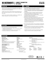
HK Instruments CDT2000 Series User manual

Type
User manual

HK Instruments CDT2000 Series carbon dioxide transmitters with optional relative humidity and temperature measurement are designed for commercial use in HVAC/R applications, such as monitoring CO2 and humidity levels in offices, public spaces, meeting rooms, and classrooms, as well as CO2 levels and humidity in ventilation systems.

HK Instruments CDT2000 Series carbon dioxide transmitters with optional relative humidity and temperature measurement are designed for commercial use in HVAC/R applications, such as monitoring CO2 and humidity levels in offices, public spaces, meeting rooms, and classrooms, as well as CO2 levels and humidity in ventilation systems.

Copyright HK Instruments 2021 www.hkinstruments. Installaon version 7.0 2021
INSTALLATION
INSTRUCTIONS
CARBON DIOXIDE TRANSMITTERS
CDT2000 Series
READ THESE INSTRUCTIONS CAREFULLY BEFORE
ATTEMPTING TO INSTALL, OPERATE OR SERVICE THIS
DEVICE.
• Failuretoobservesafetyinformaonandcomplywith
instruconscanresultinPERSONALINJURY,DEATHAND/OR
PROPERTY DAMAGE.
• Toavoidelectricalshockordamagetoequipment,disconnect
powerbeforeinstallingorservicinganduseonlywiringwith
insulaonratedforfulldeviceoperangvoltage.
• Toavoidpotenalreand/orexplosiondonotuseinpotenally
ammableorexplosiveatmospheres.
• Retaintheseinstruconsforfuturereference.
• Thisproduct,wheninstalled,willbepartofanengineered
systemwhosespecicaonsandperformancecharacteriscs
arenotdesignedorcontrolledbyHKInstruments.Review
applicaonsandnaonalandlocalcodestoassurethatthe
installaonwillbefunconalandsafe.Useonlyexperiencedand
knowledgeabletechnicianstoinstallthisdevice.
SPECIFICATIONS
ThankyouforchoosinganHKInstrumentsCDT2000seriescarbon
dioxidetransmier.TheCDT2000seriesisintendedforuseincom-
mercialenvironmentsinHVAC/Rapplicaons.
TheCDT2000seriesmeasurescarbondioxide(CO2),ulizingthein-
dustrystandardNDIRmeasurementprinciple,andtemperature(T).
Oponalrelavehumidity(rH)measurementisalsoavailableinthe
samedevice.Eachmeasurementparameter(CO2,rH,T)hasasepa-
rateeldcongurableoutput.
TheCDT2000seriescarbondioxidetransmiersareavailablewith
Modbusconguraon,relayandtouchscreendisplay.
The CDT2000 series transmiers calibrate themselves automa-
callyusingABCTMlogic.TheABCTMlogicrequiresthatthespacein
which the transmier is used needs to to be unoccupied for four
hoursperdaysothattheindoorCO2concentraondropstotheout-
sidelevel.CDT2000-DCisadualchannelmodelwithameasuring
channelandareferencechannelthatmakesaconnuouscompari-
sonandthenecessaryadjustmentaccordingly.CDT2000-DCisalso
suitableforbuildingsthatareconnuouslyoccupied.
•humidityinvariousindustrialapplicaons
•temperaturesinHVAC/Renvironment
•CDT2000-DCseriesdevicescanalsobeusedinapplicaonswhere
thereisaconstantsourceofcarbondioxidepresent(forexample
hospitalsandgreenhouses)
SPECIFICATIONS
Performance
Measurement ranges:
CO2:400–2000ppm
Temperature:0...50°C
Relavehumidity:0100%
Accuracy:
CO2:±40ppm+2%ofreading,DCmodel:75ppmor
10%ofreading(whicheverisgreater)
Temperature:<0.5ºC
Relavehumidity:±2...3%at0...50°Cand10–90%rH
Totalerrorbandincludesaccuracy,hysteresisand
temperatureeectover5...50°Cand10–90%rH.
Technical Specicaons
Media compability:
Dryairornon-aggressivegases
Measuring units:
ppm,°Cand%rH
Measuring element:
CO2:Non-dispersiveinfrared(NDIR)
Temperature: Pt1000(modelswithoutrH-measurement
 Integrated(modelswithrH-measurement)
Relavehumidity:Thermosetpolymercapacive
sensingelement
Calibraon:
Automacself-calibraonABCLogicTMorconnuous
comparison(DC)
Environment:
Operangtemperature:0...50°C
Storagetemperature:-20...70°C
Humidity:0to95%rH,noncondensing
Physical
Dimensions:
Case:99x90x32mm
Weight:
150g
Mounng:
3screwholessloed,3.8mm
Materials:
Case: ABS
Protecon standard:
IP20
Display (Oponal)
Touchscreen
Size:77.4x52.4mm
Electrical connecons:
Powersupply:
 5-screwterminalblock
 (24V,GND,CO2, rH, T)
 0.2–1.5mm2(12–24AWG)
Relay out:
 3-screwterminalblock
 (NC,COM,NO)
 0.2–1.5mm2(12–24AWG)
Electrical
Input: 24VACorVDC,±10%
Currentconsumpon:max90mA(at24V)+ 
10mAforeachvoltageoutputor20mAfor 
 eachcurrentoutput
CO2outputsignal:
 0–10V,R>1kΩ
 210V,R>1kΩ(oponalvoltageoutput,displayrequired)
 4–20mA,R<500Ω
Temperatureoutputsignal:
 0–10V,R>1kΩ
 210V,R>1kΩ(oponalvoltageoutput,displayrequired)
 4–20mA,R<500Ω
Relavehumidityoutputsignal:
 0–10V,R>1kΩ
 210V,R>1kΩ(oponalvoltageoutput,displayrequired)
 4–20mA,R<500Ω
Relay out:
 SPDTRelay,250VAC/30VDC/6A
 Adjustableswitchingpointandhysteresis
Conformance
MeetsrequirementsforCEmarking:
EMCDirecve2014/30/EU
RoHSDirecve2011/65/EU
LVDDirecve2014/35/EU
WEEEDirecve2012/19/EU
INTRODUCTION
APPLICATIONS
WARNING
CDTseriesdevicesarecommonlyusedtomonitor:
CO2andhumiditylevelsinoces,publicspaces,meengrooms
andclassrooms
CO2levelsofreturnairinvenlaonsystems
•incomingairandreturnairhumiditylevelsinvenlaonsystem
COMPANY WITH
MANAGEMENT SYSTEM
CERTIFIED BY DNV GL
= ISO 9001 = ISO 14001 =
RoHS 2
2011/65/EU
Copyright HK Instruments 2021 www.hkinstruments. Installaon version 7.0 2021
SCHEMATICS
DIMENSIONAL DRAWINGS
INSTALLATION
STEP 1: MOUNTING THE DEVICE
1)Mountthedeviceinthedesiredlocaon(seestep1).
2)Routethecablesandconnectthewires(seestep2).
3)Thedeviceisnowreadyforconguraon.
WARNING!Applypoweronlyaerthedeviceisproperlywired.
Figure 1a - Surface mounng
1)Selectamounnglocaononthewallat1.21.8m(4–6)above
theoorandatleast50cm(20in)fromtheadjacentwall.Do
notblockdeviceairventsfromanydireconandleaveatleast
20cm(8in)gaptootherdevices.Locatetheunitinanareawith
goodvenlaonandanaveragetemperature,whereitwillbe
responsivetochangestotheroomcondions.TheCDTshouldbe
mountedonaatsurface.
DonotlocatetheCDTwhereitcanbeaectedby:
•Directsunlight
•Drasordeadareasbehinddoors
•Radiantheatfromappliances
•Concealedpipesorchimneys
•Outsidewallsorunheated/uncooledareas
2)Usethedeviceasatemplateandmarkthescrewholes.
3)Mountthewallplatewithscrews.
•Incorrectinstallaonmaycauseashiintemperatureoutput
•Securethelidwithalockingscrew,iftherelayisconnectedtothe
mainspower.
Display locking
jumper
Output mode
selecon
jumpers
Contact pins for
relay terminal
Contact pins for
terminal block
Terminal block
Terminal block for relay
99.0
90.0
83.0
49.5
14.0
45.0
18.0
Ø 4.0
32.0
YES NO NO
Figure 1b - Mounng orientaon
Copyright HK Instruments 2021 www.hkinstruments. Installaon version 7.0 2021
CAUTION!
•ForCEcompliance,aproperlygroundedshieldingcableis
required.
•Usecopperwireonly.Insulateorwirenutallunusedleads.
•Supplyaseparatecableforrelayandsignaloutwhenusingline
voltagetopowertherelay.
•Anywiringmaycarrythefulloperanglinevoltagecurrentbased
oneldinstallaon.Thecoverlockingscrewmustbeinstalledif
thelinevoltageissuppliedtotherelay.
•Careshouldbeusedtoavoidelectrostacdischargetothedevice.
•Thisunithasconguraonjumpers.Youmayneedtorecongure
thisdeviceforyourapplicaon.
1)Routethecablesthroughthesquareopeninginthebackplateor
forsurfacewiringselectaknockoutonthetoporboomofthe
wallplate,asshowninFigure2a.
2)ConnectthewiresasshowninFigure2band2c.
WIRING DIAGRAMS CONTINUED
Figure 2a - Roung the cables
24 V
GND
CO2
rH
Temp
+
Output 0/2–10 V / 4–20 mA
Figure 2b - Wiring diagram: Power input & signal output
Wires can be routed through the square opening in the back plate
Wires can be routed through the top knockouts
Wires can be routed through the boom knockouts
Figure 2d - Wiring diagram: Relay
NC
COM
NO
STEP 2: WIRING DIAGRAMS
NOTE!Whenusinglongconneconwiresitmaybenecessarytousea
separateGNDwireforvoltageoutputcurrenttopreventmeasurement
distoron.TheneedforanextraGNDwiredependsonthecrosssec-
onandlengthoftheusedconneconwires.Iflongand/orsmallcross
seconwiresareused,supplycurrentandwireresistancemaygener-
ate avoltage drop in thecommon GNDwire resulngina distorted
outputmeasurement.
24 V
GND
CO
2
rH
+
Temp
V V V
Output 0/2...10 V
Output 0/2...10 V
Output 0/2...10 V
Figure 2c - Wiring diagram: Extra GND wire
STEP 3: CONFIGURATION
ConguraonoftheCDTseriesdeviceconsistsof:
1)Conguringthejumpers(seestep4).
2)Conguraonmenuopons.
(Display-andModbusversionsonly.Seetheusermanualfor
furtherdetails.)
Copyright HK Instruments 2021 www.hkinstruments. Installaon version 7.0 2021
1)Conguraonoftheoutputmodesof:
•Carbondioxide(CO2)
•Relavehumidity(rH)
•Temperature(Temp)
Selecttheoutputmode,current(4–20mA)orvoltage(0–10V),
byinstallingjumpersasshowninFigure4.Eachoutputarecong-
uredseparately.
Toselect2–10Voutputmodeonadisplayversionofthedevice:
First,select010Voutputbyjumper(s),thenchangethevoltage(V)
outputfrom0–10Vto210Vviatheconguraonmenu.Please
seetheusermanualformoredetails.
Thesellerisobligatedtoprovideawarrantyofveyearsforthedeliv-
eredgoodsregardingmaterialandmanufacturing.Thewarrantyperiod
isconsideredtostartonthedeliverydateoftheproduct.Ifadefectin
rawmaterialsoraproduconawisfound,thesellerisobligated,when
theproductissenttothesellerwithoutdelayorbeforeexpiraonof
thewarranty,toamendthemistakeathis/herdiscreoneitherbyre-
pairingthedefecveproductorbydeliveringfreeofchargetothebuy-
eranewawlessproductandsendingittothebuyer.Deliverycosts
fortherepairunderwarrantywillbepaidbythebuyerandthereturn
costsbytheseller.Thewarrantydoesnotcomprisedamagescausedby
accident, lightning, ood or other natural phenomenon, normal wear
andtear,improperorcarelesshandling,abnormaluse,overloading,im-
properstorage,incorrectcareorreconstrucon,orchangesandinstal-
laonworknotdonebythesellerorhis/herauthorizedrepresentave.
Theseleconofmaterialsfordevicespronetocorrosionisthebuyer’s
responsibility,unlessotherwiseislegallyagreedupon.Shouldtheman-
ufactureralterthestructureofthedevice,thesellerisnotobligatedto
makecomparablechangestodevicesalreadypurchased.Appealingfor
warrantyrequiresthatthebuyerhascorrectlyfullledhis/herdues
arisenfromthedeliveryandstatedinthecontract.Thesellerwillgive
anewwarrantyforgoodsthathavebeenreplacedorrepairedwithin
thewarranty,howeveronlytotheexpiraonoftheoriginalproduct’s
warrantyme.Thewarrantyincludestherepairofadefecvepartor
device, orifneeded,a new partordevice,butnotinstallaonorex-
change costs. Under no circumstance is theseller liablefor damages
compensaonforindirectdamage.
Jumper installed to the le side pins:
0–10 V output selected
CO2
rH
Temp
0–10 V 4–20 mA
Jumper installed to the right side pins:
4–20 mA output selected
CO2
rH
Temp
0–10 V 4–20 mA
First jumper installed to the right side pins:
4–20 mA output selected for CO2
Second and third jumper installed to the le side pins
0–10 V outputs selected for relave humidity & temperature
CO2
rH
Temp
0–10 V 4–20 mA
Figure 4
STEP 4: Jumper settings RECYCLING/DISPOSAL
The parts le over from installaon should be
recycled according to your local instrucons.
Decommissioned devices should be taken to a
recyclingsitethatspecializesinelectronicwaste.
WARRANTY POLICY
(Grey colour indicates that a jumper is installed)
No jumper
Circuit open
Jumper installed
Circuit closed
Jumper stored
Figure 3 - Jumper installaon
2)Lockingthedisplay:
Installthejumpertolockthedisplaytopreventaccesstothecongu-
raonmenuaerinstallaoniscompleted(seetheschemacsforthe
locaonofthepins).
  • Page 1 1
  • Page 2 2
  • Page 3 3
  • Page 4 4

HK Instruments CDT2000 Series User manual

Type
User manual

HK Instruments CDT2000 Series carbon dioxide transmitters with optional relative humidity and temperature measurement are designed for commercial use in HVAC/R applications, such as monitoring CO2 and humidity levels in offices, public spaces, meeting rooms, and classrooms, as well as CO2 levels and humidity in ventilation systems.

Ask a question and I''ll find the answer in the document

Finding information in a document is now easier with AI