Page is loading ...

Page 1 of 61
MIS-2957 A
I-TEC
®
SERIES
PACKAGED HEAT PUMP
Models:
INSTALLATION INSTRUCTIONS
Bard Manufacturing Company, Inc.
Bryan, Ohio 43506
www.bardhvac.com
Manual: 2100-549Q
Supersedes: 2100-549P
Date: 6-14-17
I30H1-A
I30H1-B
I30H1-C
I36H1-A
I36H1-B
I36H1-C
I42H1-A
I42H1-B
I42H1-C
I48H1-A
I48H1-B
I48H1-C
I60H1-A
I60H1-B
I60H1-C
I30H1DA
I30H1DB
I30H1DC
I36H1DA
I36H1DB
I36H1DC
I42H1DA
I42H1DB
I42H1DC
I48H1DA
I48H1DB
I48H1DC
I60H1DA
I60H1DB
I60H1DC

Manual 2100-549Q
Page 2 of 69
CONTENTS
Getting Other Information and Publications .........4
General ...................................................................5
ANSI Z535.5 Definitions ........................................... 5
I-TEC Series General Information .............................6
I-TEC Model Nomenclature .......................................6
Shipping Damage .....................................................9
Unit Removal from Skid ............................................9
Handling Unit After Removal from Skid ......................9
Required Steps After Final Placement ......................10
Minimum Installation Height ...................................10
Securing Unit to Structure ......................................10
Seismic Considerations ...........................................10
Duct Work..............................................................18
Filters ...................................................................18
Condensate Drain ...................................................19
Installation ..................................................................22
Mounting the Unit ..................................................22
Wiring – Main Power ...............................................22
Wiring – Low Voltage Wiring ..................................... 23
Low Voltage Connections .........................................23
General .................................................................23
Start Up ........................................................................31
General .................................................................31
Topping Off System Charge .....................................31
Safety Practices .....................................................31
Description of Standard Equipment .......................... 32
Important Installer Note ..........................................32
Phase Monitor ........................................................ 32
Three Phase Scroll Compressor Start Up Information .32
Service Hints .........................................................32
Sequence of Operation ............................................ 33
Pressure Service Ports ............................................33
Lowering Outdoor Fan Speed for Sound ....................33
Defrost Cycle .........................................................33
I-TEC Commercial Room Ventilator System
(Vent Code "M") .......................................................... 35
General Description ................................................35
Control Wiring ........................................................35
Recommended Control Sequences ...........................35
Setting the Ventilation CFM Levels ........................... 35
I-TEC Combination CRV and Economizer
Ventilation System (Vent Code "N") ......................38
General Description ................................................38
Control Wiring ........................................................38
Setting the Ventilation CFM Levels ........................... 39
I-TEC Economizer Sequence of Operation .................40
Heating Mode Operation .........................................40
Ventilation Mode ...................................................40
I-TEC Modulating Commercial Room
Ventilator System (Vent Code "Q") ........................41
General Description ................................................41
Control Wiring ........................................................41
Recommended Control Sequences ...........................41
Changing Ventilation CFM Rates in Manual Mode ......42
Changing to Fully Modulating Mode .........................42
Configuring Bard Part #8403-067 CO
2
Control
for CRV Modulating Control .....................................46
I-TEC Energy Recovery Ventilator System
(Vent Code "R") ...........................................................49
General Description ................................................49
Control Wiring ........................................................49
Recommended Control Sequences ...........................50
Changing Ventilation CFM Rates in Manual Mode ......50
Changing to Fully Modulating Mode .........................50
Configuring Bard Part #8403-067 CO
2
Control
for ERV Modulating Control .....................................55
Energy Recovery Ventilator Maintenance .................... 58
Troubleshooting .........................................................60
Solid State Heat Pump Control ................................60
Checking Temperature Sensor .................................. 61
Troubleshooting Condensate Overflow Systems ..........62
Troubleshooting ECM™ 142R Outdoor Fan Motors ....63
Troubleshooting ECM™ Indoor Blower Motors ...........65
Fan Blade Setting Dimensions .................................67
Refrigerant Charge ..................................................67

Manual 2100-549Q
Page 3 of 69
Figures
Figure 1 Unit Dimensions .................................... 8
Figure 2A Unit on Lift ........................................... 9
Figure 2B Unit Side .............................................. 9
Wall Mounting Bracket Location ............ 10
Bracket Wall Section View .................... 11
Wood Framed Installation ..................... 11
Figure 3 Center of Gravity .................................. 12
Figure 4 Required Clearances and
Recommended Access.......................... 13
Figure 5 Compressor Shipping Bolts ................... 14
Figure 6 Removal of Air Duct ............................. 14
Figure 7A Ducted Application – Basic Unit ............ 15
Figure 7B 3" Riser Application ............................. 16
Figure 7C 6" Riser Application ............................. 17
Figure 8 Supply Duct Connections ...................... 18
Figure 9 Filter Location ..................................... 18
Figure 10 Drain Header Assembly as Shipped
and Installed ....................................... 19
Figure 11A Unit Mounting ..................................... 20
Figure 11B Unit Mounting ..................................... 21
Figure 12 Component Location ............................ 22
Figure 13 Basic Heat Pump w/No Vent Pkg
("X" Vent) ............................................. 24
Figure 14 HP w/CRV, without CO
2
Control
("M" Vent) ............................................ 25
Figure 15 HP with CRV & CO
2
Control ("M" Vent) .... 26
Figure 16 HP with ERV, w/o CO
2
Control ("R" Vent) . 27
Figure 17 HP with ERV & CO
2
Control ("R" Vent) .... 28
Figure 18 HP w/ERV & CO
2
Control
(Fully Mod.) ("R" Vent) and
HP w/Mod. CRV ("Q" Vent) ..................... 29
Figure 19 HP w/Comb. CRV & DB Econ. ("N" Vent) ... 30
Figure 20 Defrost Cycle ....................................... 34
Figure 21 CRV Motor Speed/CFM Configuration ..... 36
Figure 22 CRV Speed Change Terminal Access ...... 37
Figure 23 Economizer Control Circuit ................... 38
Figure 24 Motor Speed/CFM Configuration ............ 39
Figure 25A CRV Manual Mode "M" Terminal ............ 43
Figure 25B CRV Mod. Mode "P" Terminal ................ 43
Figure 26 Ventilation Airflow Diagram ................... 44
Figure 27 CRV Control Access .............................. 45
Figure 28 Control Board Configuration/Setting ....... 46
Figure 29A ERV Manual Mode "M" Terminal ............ 52
Figure 29B ERV Mod. Mode "P" Terminal ................ 52
Figure 30 Ventilation Airflow Diagram ................... 53
Figure 31 ERV Control Access .............................. 54
Figure 32 Control Board Configuration/Setting ....... 55
Figure 33 Hub Assembly w/Ball Bearings .............. 59
Figure 34 Indoor Condensate Overflow Switch ....... 62
Figure 35 Outdoor Condensate Sensor .................. 62
Figure 36 Outdoor Condensate Control .................. 62
Figure 37 Control Disassembly ............................. 66
Figure 38 Winding Test ....................................... 66
Figure 39 Drip Loop ............................................ 66
Figure 40 Control Connector Motor Half ................ 67
Tables
Table 1 Factory Built-In Electric Heat Table ........ 6
Table 1A Indoor Blower Performance .................... 6
Table 2 Electrical Specifications ........................ 7
Center of Gravity Reference Table ......... 12
Table 3 Operating Voltage Range ...................... 23
Table 4 Wall Thermostats ................................ 23
Low Voltage Connections
for DDC Control .................................. 23
Performance and Application Data:
Summer Cooling & Winter Heating ........51
Table 5 Troubleshooting .................................. 60
Table 6 Temperature (F) vs. Resistance (R)
of Temperature Sensor ......................... 61
Table 7 Troubleshooting ECM™ 142R
Outdoor Fan Motors ............................ 64
Table 8 Cooling Mode ..................................... 64
Table 9 Heat Pump Mode ................................ 64
Troubleshooting ECM™ Indoor
Blower Motors .................................... 67
Power Connector .................................67
Table 10A
Full Load Cooling
Pressure/Temperature .......................... 68
Table 10B
Full Load Heating
Pressure/Temperature .......................... 68
Table 11A
Part Load Cooling
Pressure/Temperature ......................... 69
Table 11B
Part Load Heating
Pressure/Temperature .......................... 69

Manual 2100-549Q
Page 4 of 69
GETTING OTHER INFORMATION AND PUBLICATIONS
These publications can help when installing the air
conditioner or heat pump. They can usually be found
at the local library or purchase them directly from the
publisher. Be sure to consult current edition of each
standard.
National Electrical Code ..................... ANSI/NFPA 70
Standard for the Installation ............. ANSI/NFPA 90A
of Air Conditioning and Ventilating Systems
Standard for Warm Air ...................... ANSI/NFPA 90B
Heating and Air Conditioning Systems
Load Calculation for ...................... ACCA Manual J or
Winter and Summer Manual N
Air Conditioning
Low Pressure, Low Velocity ............ ACCA Manual D or
Duct System Design Manual Q
Winter and Summer Air Conditioning
FOR MORE INFORMATION, CONTACT
THESE PUBLISHERS:
ACCA Air Conditioning Contractors of America
1712 New Hampshire Avenue
Washington, DC 20009
Telephone: (202) 483-9370
Fax: (202) 234-4721
ANSI American National Standards Institute
11 West Street, 13th Floor
New York, NY 10036
Telephone: (212) 642-4900
Fax: (212) 302-1286
ASHRAE American Society of Heating, Refrigeration,
and Air Conditioning Engineers, Inc.
1791 Tullie Circle, N.E.
Atlanta, GA 30329-2305
Telephone: (404) 636-8400
Fax: (404) 321-5478
NFPA National Fire Protection Association
Batterymarch Park
P.O. Box 9101
Quincy, MA 02269-9901
Telephone: (800) 344-3555
Fax: (617) 984-7057

Manual 2100-549Q
Page 5 of 69
GENERAL
The equipment covered in this manual is to be installed
by trained, experienced service and installation
technicians.
The I-TEC must be installed with the Bard
manufactured IWS wall sleeve and ILG louver
grille accessories. These are sold as separate
accessories. Any substitutions will void the
manufacturer’s warranty.
The unit is designed for use with or without ductwork.
For use without ductwork, Plenum Box IPBDF8-
color (8" height) or IPBDF12-color (12" height) is
recommended.
These instructions explain the recommended method
to install the air cooled self-contained unit and the
electrical connections to it.
These instructions and any instructions packaged
with any separate equipment required to make up the
entire heating and air conditioning system should be
carefully read before beginning the installation. Note
particularly “Start Procedure” and any tags and/or
labels attached to the equipment.
While these instructions are intended as a general
recommended guide, they do not supersede any
national and/or local codes in any way. Authorities
having jurisdiction should be consulted before the
installation is made. See page 4 for information on
codes and standards.
Size of unit for a proposed installation should be based
on heat loss or heat gain calculation made according
to methods of Air Conditioning Contractors of America
(ACCA). The air duct should be installed in accordance
with the Standards of the National Fire Protection
Systems of Other Than Residence Type, NFPA No.
90A, and Residence Type Warm Air Heating and Air
Conditioning Systems, NFPA No. 90B. Where local
regulations are at a variance with instructions, installer
should adhere to local codes.
ANSI Z535.5 Definitions:
• DANGER: Indicate[s] a hazardous situation which, if
not avoided, will result in death or serious injury. The
signal word “DANGER” is to be limited to the most
extreme situations. DANGER [signs] should not be used
for property damage hazards unless personal injury risk
appropriate to these levels is also involved.
• WARNING: Indicate[s] a hazardous situation which,
if not avoided, could result in death or serious injury.
WARNING [signs] should not be used for property
damage hazards unless personal injury risk appropriate
to this level is also involved.
• CAUTION: Indicate[s] a hazardous situation which, if
not avoided, could result in minor or moderate injury.
CAUTION [signs] without a safety alert symbol may be
used to alert against unsafe practices that can result in
property damage only.
• NOTICE: [this header is] preferred to address
practices not related to personal injury. The safety alert
symbol shall not be used with this signal word. As an
alternative to “NOTICE” the word “CAUTION” without
the safety alert symbol may be used to indicate a
message not related to personal injury.

Manual 2100-549Q
Page 6 of 69
TABLE 1
Factory Built-In Electric Heat Table
Models I30H1-A I30H1-B I30H1-C
I36H1-A
I42H1-A
I36H1-B
I42H1-B
I36H1-C
I42H1-C
I48H1-A
I48H1-B
I60H1-B
I48H1-C
I60H1-C
I60H1-A
KW
240V-1 208V-1 240V-3 208V-3 460V-3 240V-1 208V-1 240V-3 208V-3 460V-3 240V-1 208V-1 240V-3 208V-3 460V-3 240V-1 208V-1
BTUH BTUH BTUH BTUH BTUH BTUH BTUH BTUH BTUH BTUH BTUH BTUH BTUH BTUH BTUH BTUH BTUH
4.0 13,652 10,239
5.0 17,065 12,799 17,065 12,799 17,065 12,799 17,065 12,799
6.0 20,478 15,359 20,478 20,478 15,359 20,478 20,478 15,359 20,478
9.0 30,717 23,038 30,717 30,717 23,038 30,717 30,717 23,038 30,717
10.0 34,130 25,598 34,130 25,598 34,130 25,598 34,130 25,598
15.0 51,195 38,396 51,195 38,396 51,195 51,195 38,396 51,195 38,396 51,195 51,195 38,396
18.0 61,434 46,076 61,434
20.0 68,260 51,195 68,260 51,195
I-TEC Series General Information
I-TEC MODEL NOMENCLATURE
I 36 H 1 D A 0Z R P 4 X X 2
SPECIAL UNITS
(–) – Standard
D – Dehum.
REVISION
VOLTS & PHASE
A – 230/208, 60-1
B – 230/208, 60-3
C – 460-60-3
COIL TREATMENT
X – Std. Hydrophilic Fin Evap. &
Uncoated Alum. Cond. Coil
1 – Phenolic Coated ID Coil
2 – Phenolic Coated OD Coil
3 – Phenolic Coated ID & OD Coil
CONTROLS
X – 24V Terminal Block Only w/o
CompleteStat
TM
1 – CompleteStat
TM
THO (Temp,
Humidity & Occupancy)
2
– CompleteStat
TM
THO w/CO
2
3 – CompleteStat
TM
THO w/
Ethernet
4
– CompleteStat
TM
THO w/CO
2
&
Ethernet
MODEL
SERIES
NOMINAL
CAPACITY
30 – 30,000 BTUH
36 – 36,000
42 – 42,000
48 – 48,000
60 – 60,000
ELECTRIC HEAT
0Z – No heat w/breaker
04 – 4KW 1-Phase
05 – 5KW 1-Phase
06 – 6KW 3-Phase
09 – 9KW 3-Phase
10 – 10KW 1-Phase
15 – 15KW 1 & 3-Phase
18 – 18KW 3-Phase
20 – 20KW 1-Phase
VENTILATION OPTIONS
B – Blank-Off Plate
M – Multi-Speed CRV
N – Multi-Speed CRV with
Economizer Mode
Q – Modulating CRV (0-10Vdc)
R – ERV
FILTER OPTIONS
P – 2" Pleated MERV 8
M – 2" Pleated MERV 11
N – 2" Pleated MERV 13
COLOR OPTIONS
X – Beige paint
1 – White paint
4 – Gray paint
SYSTEM TYPE
HEAT PUMP
RESERVED
NOTE: CompleteStat
TM
must be
field-installed and wired. All units
have 24V terminal block.
Motor will deliver consistent CFM through voltage supply range with no deterioration.
Continuous fan CFM is the total air being circulated during continuous fan mode.
Will operate at rated Full Load Airflow when operating with Heat Pump.
Will occur automatically with a call for "W3" or "Emergency Heat" signal from the thermostat (Heat Pump Operation is
terminated at this condition).
TABLE 1A
Indoor Blower Performance
MODEL
Rated
ESP
MAX
ESP
Continuous
Airflow
Rated 2nd
Stage CFM
Rated 1st
Stage CFM
4 – 10KW
CFM
15 – 20KW
CFM
I30H1 .15 0.50 500 900 650 700 1050
I36H1 .15 0.50 600 1150 850 700 1050
I42H1 .20 0.50 650 1300 950 700 1050
I48H1 .20 0.50 725 1500 1050 700 1400
I60H1 .20 0.50 850 1700 1200 700 1400

Manual 2100-549Q
Page 7 of 69
TABLE 2
Electrical Specifications
MODEL
Rated
Volts, Hertz
& Phase
Single Circuit Dual Circuit
No. Field
Power
Circuits
Minimum
Circuit
Ampacity
Maximum
External
Fuse or Ckt.
Brkr.
Field
Power Wire
Size
Ground
Wire
Minimum
Circuit
Ampacity
Maximum
External Fuse or
Ckt. Breaker
Field Power
Wire Size
Ground Wire
Size
Ckt. A Ckt. B Ckt. A Ckt. B Ckt. A Ckt. B Ckt. A Ckt. B
I30H1-A0Z
A05
A10
230/208-1
1
1
1 or 2
22
48
74
35
50
80
8
8
4
10
10
8 48 30 50 30 8 10 10 10
I30H1-B0Z
B06
B09
230/208-3
1
1
1
17
35
44
25
35
45
10
8
8
10
10
10
I30H1-C0Z
C06
C09
460-3
1
1
1
9
18
22
10
20
25
14
12
10
14
12
10
I36H1-A0Z
A05
A10
A15
230/208-1
1
1
1 or 2
1 or 2
26
52
78
84
40
60
80
90
8
6
4
4
10
10
8
8
26
26
52
52
40
40
60
60
8
8
6
6
10
10
10
10
I36H1-B0Z
B06
B09
B15
230/208-3
1
1
1
1
22
40
49
51
30
45
50
60
10
8
8
6
10
10
10
10
I36H1-C0Z
C06
C09
C15
460-3
1
1
1
1
11
20
24
28
15
20
25
30
14
12
10
10
14
12
10
10
I42H1-A0Z
A05
A10
A15
230/208-1
1
1
1 or 2
1 or 2
30
56
82
82
45
60
90
90
8
6
4
4
10
10
8
8
56
56
26
52
60
60
30
60
6
6
10
6
10
10
10
10
I42H1-B0Z
B06
B09
B15
230/208-3
1
1
1
1
25
43
52
52
35
50
60
60
8
8
6
6
10
10
10
10
I42H1-C0Z
C06
C09
C15
460-3
1
1
1
1
12
21
26
28
15
25
30
30
14
10
10
10
14
10
10
10
I48H1-A0Z
A04
A05
A10
A15
A20
230/208-1
1
1
1 or 2
1 or 2
1 or 2
1 or 2
34
54
59
85
85
110
50
60
70
90
90
110
8
6
6
3
3
2
10
10
8
8
8
6
35
35
35
59
26
52
52
52
45
45
45
60
30
60
60
60
8
8
8
6
10
6
6
6
10
10
10
10
10
10
10
10
I48H1-B0Z
B06
B09
B15
B18
230/208-3
1
1
1
1
1
26
44
53
53
53
35
50
60
60
60
8
8
6
6
6
10
10
10
10
10
I48H1-C0Z
C06
C09
C15
C18
460-3
1
1
1
1
1
12
21
26
26
26
20
30
30
30
30
12
10
10
10
10
12
10
10
10
10
I60H1-A0Z
A05
A10
A15
A20
230/208-1
1
1 or 2
1 or 2
1 or 2
1 or 2
44
70
96
96
112
60
80
100
100
120
8
4
3
3
2
10
8
8
8
6
44
44
44
60
26
52
52
52
60
60
60
60
30
60
60
60
8
8
8
6
10
6
6
6
10
10
10
10
10
10
10
10
I60H1-B0Z
B06
B09
B15
B18
230/208-3
1
1
1
1
2
31
49
58
58
45
60
60
60
8
8
6
6
10
10
10
10
31 54 45 60 8 6 10 10
I60H1-C0Z
C06
C09
C15
C18
460-3
1
1
1
1
1
15
25
29
29
29
20
30
30
30
30
12
10
10
10
10
12
10
10
10
10
These “Minimum Circuit Ampacity” values are to be used for sizing the field power conductors. Refer to the National Electric Code (latest
revision), article 310 for power conductor sizing.
Caution: When more than one field power conductor circuit is run through one conduit, the conductors must be derated. Pay special
attention to note 8 of table 310 regarding Ampacity Adjustment Factors when more than three conductors are in a raceway.
Maximum size of the time delay fuse or circuit breaker for protection of field wiring conductors.
Based on 75°C copper wire. All wiring must conform to the National Electrical Code and all local codes.
Maximum KW that can operate with heat pump on is 10KW for 1-Phase and 9KW for 3-Phase.
Represents Electric Heat Only. Electrical Control Circuit will lockout Heat Pump Operation.

Manual 2100-549Q
Page 8 of 69
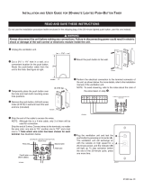
3
3
4
"
24
1
2
"
22
1
4
"
Lower
Section
71
3
4
"
Upper
Section
Supply
Air
Return
Air
Return
Air
Inner
Sleeve
Outer
Sleeve
Outer
Sleeve
Inner
Sleeve
Unit Drain
(2) Opt.
Entrances
Unit Specification Sheet
Top View
Front View
Right Side View
MIS-3831
(2) Side
Handles
Back View
Return Air
Filters
(4) Lift-Off
Hinges
Air Filters
Vent Exhaust
(2) 12" x 20"
Air Filters
Vent Intake
(2) Washable
Control Panel
Electric Heat
Wire Channel
Disconnect
Electrical
Door Latch
Locking
Door Latch
Locking
(2) 2"x24"x30"
Front Forklift Holes
(Remove Front Trim)
4
58"
"
8
15
5
"13
1
94"
Total
Height
Openings
(2) Return
Side Forklift Holes
(Remove Sides)
2
"
71
1
30" With Doors and
Sides Removed
Entrance Entrance
High Voltage
Low Voltage
20" x 24" Supply Frame
1
2
4
"
Total Depth
"
3
8
"
4
26
3
"
2"
20"
8
11
7
"
4
11
1
" Total Width
8
31
5
47
24"
"
1
4
"
4
28
1
3
46
1
8
" With Sides Removed
Rear Collector
Assembly
(4) UNIT
DRAINS
8"
3
1
8
" 3
1
8
"
FIGURE 1
Unit Dimensions

Manual 2100-549Q
Page 9 of 69
SHIPPING DAMAGE
Upon receipt of equipment, the unit should be checked
for external signs of shipping damage. The skid must
remain attached until the unit is ready for installation.
If damage is found, the receiving party must contact
the last carrier immediately, preferably in writing,
requesting inspection by the carrier’s agent.
UNIT REMOVAL FROM SKID
HANDLING UNIT AFTER REMOVAL
FROM SKID
If a wide and tall enough opening exists, the I-TEC can
be moved as a complete assembled unit. If not, it is
designed to break down into two sections to allow it to
pass through a 36" wide door.
1. Depress and release both top and bottom door latches
and open doors.
2. Remove the doors by lifting straight up and off from
the hinge pins.
3.
Remove cabinet sides by first removing the four (4)
sheet metal screws from the front (leading edge) of the
side panel. The panel will not fall off. Swing the panel
away from the chassis 20-30˚ and then pull forward
from the two (2) tabs supporting the rear edge.
4. On each side of the unit is a tie plate that secures
the top and bottom sections with four (4) cap bolts.
Using a ½" wrench or socket, remove these screws
from both plates and set aside.
5. If the unit is equipped with a CRV or ERV, unplug the
wire harness on the left-hand side of the control box.
6. A forklift or a lift rated for the load is required to lift
the top section off from the bottom base. Do not
attempt to do this manually. Failure to do so could
result in the unit tipping over and causing bodily
injury and/or damage to the unit.
7. The top section can be forked from either the
right-hand or left-hand side. See Figure 1 for fork
openings.
8. Carefully lift the top section straight up avoiding tipping.
9. Move the top section through the doorway and place
on flat surface free of debris.
10. The bottom base can now be moved through the
doorway the same way.
11. Reassemble the unit by reversing this procedure.
FIGURE 2A – Unit on Lift
FIGURE 2B – Unit Side
A forklift or a lift rated for the load (Figure 2A) is
required to lift the unit off from the skid. This unit is
top heavy and should never be tipped while moving it.
The I-TEC is designed to be lifted off the skid from the
front or rear of the unit without having to remove any
doors or side panels. See Figure 1 for fork openings.
The shipping brackets on front and rear of the unit
must be removed and discarded. The unit can now
be lifted straight up and the skid can be slid out from
underneath.
ERV/CRV
HARNESS CONNECTION
TIE PLATE
(Covers entire width; shortened for illustration
purposes to show Fork Openings)
FORK OPENING
(Visible after removing
tie plate)
(4) CAP BOLTS
WARNING
This unit is heavy and requires more than one person
to handle during installation and removal from the skid.
Extreme caution must be taken to prevent injury to
personnel and damage to the unit. Use appropriate safety
equipment, including gloves when handling. Failure to do
so may result in serious injury.
Tip unit from left side only.
Failure to do so may result in injury due to
unit top-heaviness or compressor damage!

Manual 2100-549Q
Page 10 of 69
REQUIRED STEPS AFTER FINAL
PLACEMENT
The compressor is secured to the base with two (2)
bolts for shipping. Although the unit will perform as
designed with the shipping bolts in place, there may
be a noticeable additional noise and vibration noted.
To obtain the lowest noise and vibration levels, remove
the shipping bolts after the unit is in its final operating
location. To gain access to the compressor, the
compressor access panel must be removed (Figure 9).
Once this panel is removed, the CRV/ERV air duct must
be removed (see Figure 6).
The air duct is removed by pulling it straight out;
there are no screws securing it in place. Both the top
and bottom slide at the same time (pull hard). Once
removed, the compressor is visible as well as the tags
on the shipping bolts (Figure 5).
After the compressor shipping bolts have been
removed, the CRV/ERV air duct can be slid back in
place and the compressor access panel attached.
MINIMUM INSTALLATION HEIGHT
The minimum installation height to the bottom of
the roof or fixed ceiling for ducted applications is 9'
7". This provides enough clearance to install the duct
work. See Figure 7A.
The IWS Series wall sleeve has a built-in vertical
adjustment to fit window sill heights from 31-34".
If additional height is required, two riser platform
accessories are available. The IRP3 increases the unit
height by 3" (Figure 7B) and the IRP6 by 6" (Figure 7C).
Several construction options are available for unit
installation of the IZ Series. Serviceability and filter
access must be considered before installing. See
Figure 5D for required clearances and recommended
service access dimensions.
SECURING UNIT TO STRUCTURE
Shipped with the I-TEC unit is a wall mounting bracket
(screwed to shipping skid on backside of unit). This
bracket can be utilized to secure the top portion of the
unit to the wall using the appropriate field-supplied
hardware based upon the material being fastened to.
(There are several offset holes, sized to accept up to a
1/4" diameter fastener, that will easily allow studs to be
hit on a framed wall.) See Bracket Wall Section View
for locating this top wall bracket which will need to be
applied after the unit is located in the final position.
Additional/optional mounting holes for up to a 3/8"
diameter fastener are also available in the backside of
the unit. These can be accessed by:
• removing the air filters for the uppermost set
• removing the compressor section service door for
the lower set
Refer to Wood Framed Installation for additional
framing required to secure unit to wall.
The additional/optional mounting holes will require a
long extension to drive the fasteners.
SEISMIC CONSIDERATIONS
The I-TEC product features several locations for
product securement but all site conditions are
different. Consult with a licensed Seismic Engineer
to advise of particular needs when attaching the I-TEC
unit to the structure.
Wall Mounting Bracket Location
MIS-3029
2"
1 11/16"
43 3/8"
Ø1/4"
94" FROM BOTTOM
OF BRACKET TO
FLOOR WITHOUT
RISER KIT
7/8"
3/4"
1 1/2"
BRACKET

Manual 2100-549Q
Page 11 of 69
7 3/8
18 3/4
35"
17.5"
C
L
Right Side View
Front (Wall Only) View
Wall Section View
MIS-2918 D
C
L
RISER KIT DIM A DIM B DIM C
NONE 31"-34" MAX 29 17/32" 94 1/8"
IRP-3 (3") 34"-37" MAX 32 17/32" 97 1/8"
IRP-6 (6") 37"-40" MAX 35 17/32" 100 1/8"
Outside
Grille
Telescoping
Floor
Unit
Optional
Wall Sleeve**
Duct
Ceiling
Wall
Optional
Trim or
Supply Duct
Box
31" Min.
34" Max.
Mounting holes
(4) optional Unit
Opening
Centered on
* Higher Sill Heights Acheivable With Base Kit.
*
** Separate telescoping sleeves available for different wall thicknesses.
*
Bracket
Wall
Optional Top
Outside
Room Floor Level
(4) optional Unit
Mounting holes
Sleeve Mounting
Hole Locations
FLOOR MOUNTING HOLE
& CENTERLINES
7
"20
8
"
DIM B
8"
2
56
1
"
8"
6"
8
20
7
20
7
8
"
15
DIM A
48-1/2" Max.
48" Min.
1
3"
"
8
49
3
Centered
"
8
Centered
43-1/4" Max.
20"
42-3/4" Min.
"
7
43
20"
20"20"
"
11
16
16
DIM C
4
43
3
8
"
6.00
41.75
20.88
29.568.00
8.0036.88
56.50
*
riser kit. If unit uses riser kit add
appropriate dimension to height.
* Height dimension shown without
Floor
Unit
Inner wall
(4) lower fastener
holes
(4) Upper
fastener holes
MIS-3072
Bracket Wall Section View
Wood Framed Installation (for Wall Attachment)

Manual 2100-549Q
Page 12 of 69
FIGURE 3
Center of Gravity
"Y"
"X"
"Z"
MIS-3269
CENTER OF GRAVITY
UNIT TESTED
FRONT OF UNIT
DOOR TO CENTER
LEFT SIDE
TO CENTER
FLOOR TO CENTER
CRV & ERV
FLOOR TO CENTER
NO VENT
"X" Dimension "Y" Dimension "Z" Dimension "Z" Dimension
I30H1-A, -B 14" 24" 43½" 47"
I30H1-C 14" 24¼" 43½" 47"
I36H1-A, -B 14" 24" 43½" 47"
I36H1-C 14" 24¼" 43½" 47"
I42H1-A, -B 14" 24" 43½" 47"
I42H1-C 14" 24¼" 43½" 47"
I48H1-A, -B 14" 24" 43½" 47"
I48H1-C 14" 24¼" 43½" 47"
I60H1-A, -B 14" 24" 43½" 47"
I60H1-C 14" 24¼" 43½" 47"

Manual 2100-549Q
Page 13 of 69
FIGURE 4
Required Clearances and Recommended Access
12" MIN.
FOR RIGHT
SIDE
ACCESS
12" MIN.
FOR LEFT
SIDE
ACCESS
12" MIN.
12" MIN.
12" MIN.
12" MIN.
0" REQUIRED
12" RECOMENDED
0" REQUIRED
12" RECOMENDED
48" MIN.
31 3/8"
12" MIN.12" MIN.
48"
MIN. FOR
FILTER ACCESS
24" MIN. 24" MIN.
MIS-3273
RECOMMENDED SERVICE
WING WALL CONSTRUCTION TOP VIEW
CLOSET CONSTRUCTION TOP VIEW
LEFT CORNER CONSTRUCTION TOP VIEW
FILTERS
RIGHT CORNER CONSTRUCTION TOP VIEW
ACCESS DIMENSIONS
REMOVABLE
SIDES
1
1 ALL FILTER AND COMPONENT
ACCESS IS FROM THE FRONT.
COILS CAN BE CLEANED FROM
THE FRONT, BUT SIDES ARE
EASILY REMOVED FOR ENHANCED
ACCESS.
IMPORTANT
Unit can be located in corner
with 0" clearance as long as
other side is unobstructed

Manual 2100-549Q
Page 14 of 69
COMPRESSOR
SHIPPING BOLT
COMPRESSOR
SHIPPING BOLT
CRV/ERV
AIR DUCT
FIGURE 5
Compressor Shipping Bolts
FIGURE 6
Removal of Air Duct

Manual 2100-549Q
Page 15 of 69
9'-2"
MINIMUM
REQUIRED
INSTALLATION
HEIGHT
CLEARANCE
RECOMMENDED TO
BOTTOM OF ROOF
9'-7" MINIMUM
OR FIXED CEILING
FLOOR
OR FIXED CEILING
BOTTOM OF ROOF
SUSPENDED
CEILING
20"
MINIMUM
7'-9 3/4"
UNIT HEIGHT
FIELD SUPPLIED DUCT
TURNING VANES
RECOMMENDED
MINIMUM
12"
4" MINIMUM FROM
TOP OF UNIT TO
DUCT BOTTOM
MIS-2958 B
FIGURE 7A
Ducted Application – Basic Unit

Manual 2100-549Q
Page 16 of 69
9'-5"
MINIMUM
REQUIRED
INSTALLATION
HEIGHT
CLEARANCE
RECOMMENDED TO
BOTTOM OF ROOF
9'-10" MINIMUM
OR FIXED CEILING
3" RISER
FIELD SUPPLIED DUCT
TURNING VANES
RECOMMENDED
12"
MINIMUM
4" MINIMUM FROM
TOP OF UNIT TO
DUCT BOTTOM
MIS-2989 B
FLOOR
OR FIXED CEILING
BOTTOM OF ROOF
SUSPENDED
CEILING
MINIMUM
20"
7'-9 3/4"
UNIT HEIGHT
FIGURE 7B
3" Riser Application

Manual 2100-549Q
Page 17 of 69
10'-1" MINIMUM
CLEARANCE
RECOMMENDED TO
BOTTOM OF ROOF
OR FIXED CEILING
6" RISER
9'-8"
MINIMUM
REQUIRED
INSTALLATION
HEIGHT
BOTTOM OF ROOF
FLOOR
OR FIXED CEILING
SUSPENDED
CEILING
MINIMUM
20"
7'-9 3/4"
UNIT HEIGHT
FIELD SUPPLIED DUCT
MIS-2988 B
TURNING VANES
RECOMMENDED
12"
MINIMUM
4" MINIMUM FROM
TOP OF UNIT TO
DUCT BOTTOM
FIGURE 7C
6" Riser Application

Manual 2100-549Q
Page 18 of 69
DUCT WORK
Any heat pump is more critical of proper operating
charge and an adequate duct system than a straight air
conditioning unit. All duct work must be properly sized
for the design airflow requirement of the equipment.
Air Conditioning Contractors of America (ACCA) is
an excellent guide to proper sizing. All duct work or
portions thereof not in the conditioned space should be
properly insulated in order to both conserve energy and
prevent condensation or moisture damage. When duct
runs through unheated spaces, it should be insulated
with a minimum of 1" of insulation. Use insulation
with a vapor barrier on the outside of the insulation.
Flexible joints should be used to connect the duct
work to the equipment in order to keep the noise
transmission to a minimum.
The I-TEC series heat pump has provision to attach a
supply air duct to the top of the unit. Duct connection
size is 20" x 24". The flanges are shipped flat and
must be bent upward using sheet metal flanging pliers.
The duct work is field supplied. See Figure 8 for
suggested attachment method.
Make sure to seal the slots in the bend-up flange at the
time of securing your ductwork to the flange. This can
be accomplished with either foil tape or caulk. Failing
to do so may cause air leakage/whistling of air.
NOTE: Unit cabinet, supply air duct and duct free
plenum are approved for “0” clearance to
combustible material.
The I-TEC series heat pumps are designed for use with
free return (non-ducted) and either duct free with the
use of IPBDF Series Plenum Box (8" or 12") or a duct
supply air system.
The IPBDF Plenum Box mounts on top of the unit and
has both vertically and horizontally adjustable louvers
on the front discharge grille.
When used with a ducted supply, an ICX9 or ICX10
Cabinet Extension may be used to conceal the ductwork
above the unit to the ceiling. The ICX9 extends 20"
above the unit for a total height of 9'-6" for a floor
mounted install (9'-9" with IRP3 riser & 10'-0" with
IRP6 riser). The ICX10 extends 28" above the unit for
a total height of 10'-2" for a floor mounted install (10'-
5" with IRP3 riser & 10'-8" with IRP6 riser).
The unit is equipped with a variable speed indoor
blower motor which increases in speed with an increase
in duct static pressure. The unit will therefore deliver
proper rated airflow up to the maximum ESP shown
in Table 1A. However, for quiet operation of the
air system, the duct static should be kept as low as
practical, within the guidelines of good duct design.
FILTERS
Two 2" throw away filters (24 x 30) and two 1" throw
away filters (12 x 20) are supplied with each unit. The
2" filters slide into brackets on both sides for the return
air openings. The 1" filters are in the cabinet doors
for the vent (room air) exhaust. If a CRV or ERV vent
option is used, there are two additional ½" (8 x 17)
washable filters included with that option. See Figure
9 for specific locations. The filters are serviced from
the inside of the building by opening the cabinet doors,
and do not require any tools to access.
12" X 20" X 1"
FILTERS
24" X 30" X 2"
FILTERS
ACCESS TO
WASHABLE
FILTERS
COMPRESSOR
ACCESS
INDOOR
BLOWER
ACCESS
VENT
OPTION
ACCESS
MIS-2959
SUPPLY DUCT AND
FASTENERS TO BE
FIELD SUPPLIED
24"
20"
BEND THE PROVIDED
SUPPLY FRAME FLANGES
UP FOR DUCT INSTALLATION
ACCESS TO
WASHABLE FILTERS
COMPRESSOR
ACCESS
INDOOR
BLOWER
ACCESS
VENT
OPTION
ACCESS
FIGURE 8
Supply Duct Connections
FIGURE 9
Filter Location

Manual 2100-549Q
Page 19 of 69
CONDENSATE DRAIN
There are four condensate drain connections from
the condenser drain pan (compressor area). These
are visible from the rear of the unit.
The drain header
assembly is field installed and can be found attached to
the back of the vent section (see Figure 10). The drain
header assembly is to be removed from the vent section
and connected to the four drain outlets from the unit.
The required hose clamps for the four connections are
zip tied to the header assembly.
Access plates are located on the rear of the unit for
servicing the drain trap (see Figure 10). If the drain
line is to be routed through an unconditioned space, it
must be protected from freezing.
The condensate drain line can also be routed back
into the unit through either the right-hand or left-hand
optional drain locations on the rear of the unit (see
Figure 10). The holes are covered by insulation on the
inside of the unit and will have to be cut away. Located
inside the unit, about 12" in from the front on both
the left and right side, are drain holes in the bottom
of the base. These holes are covered with insulation
and are not visible. They are located very close to the
side panels and can be found by pressing down on the
insulation. Cut insulation away to expose the hole. A
drain trap can now be installed inside of the cabinet,
and the drain hose routed directly through the floor.
Once the I-TEC is installed, the rear drains exiting the
condenser section can be easily serviced with removal
of the pre-painted metal sides (lift-off doors, remove
four [4] screws to remove side).
If side access is not available, the drain lines and trap
can be serviced by removing either one of the drain
access panels on the rear of the unit (in the ventilation
package area.)
With No Vent Option
To access the drain access panels in the rear of this
section, simply remove the front door/cover from the
box, and the plates are located in the rear of the box.
With Commericial Room Ventilator
1. Open hinged front doors.
2. Disconnect unit power to eliminate shock hazard.
3. Remove front cover/door of CRV vent package.
(Can leave filter access panels in place.)
4. Unplug wires coming in on left side from upper
unit section.
5. Unplug two wire harness from front (intake) blower.
6. Remove two (2) screws securing front (intake)
blower and slide blower out of unit.
7. Remove four (4) screws that retain the partition
behind/beneath intake blower removed in Step #6.
8. Rear drain access panels are now visible on both
right-hand and left-hand sides in rear of box.
With Energy Recovery Ventilator
To access the rear drain access panels of this section:
1. Open hinged front doors.
2. Disconnect unit power to eliminate shock hazard.
3. Remove front cover/door of ERV vent package.
(Can leave filter access panels in place.)
4. Unplug wires coming in on left side from upper
unit section.
The unit is shipped from the factory with the drain
header disconnected from the unit. This is done to
allow for the installer to connect the drain header so
that water drains towards the wall drain. The drain
header assembly comes assembled with a longer hose
on the side that should be installed towards the wall
drain (if the room has drains installed).
The drain can be routed directly through the floor or
through the wall. There are also two optional drain
locations in the lower rear back panel.
The I-TEC design does not require a trap in the
condensate disposal tubing. Check local codes to see
if a “P” trap is required.
For a stand pipe floor drain or through the wall, there
is adequate hose length to reach anything located
behind the unit. The lower rear portion of the cabinet is
recessed approximately 4" allowing room for a “P” trap to
be installed with the cabinet flush with the wall. Keep in
mind, the drain line must be able to be removed from the
unit if necessary to remove the unit from the wall.
DRAIN OUTLET
WALL/ROOM DRAIN
LONGER HOSE
ON SIDE WITH
WALL/ROOM DRAIN
DRAIN HEADER ASSEMBLY
TO DRAIN OUTLETS
ATTACH HEADER
CLAMPS AND
USE PROVIDED
CLAMPS TO SECURE
HEADER TO DRAIN OUTLETS
REMOVE NYLON
INSTALL DRAIN OUTLET
ON SAME SIDE AS
WALL DRAIN
MIS-3832
FIGURE 10
Drain Header Assembly as Shipped and Installed
DRAIN OUTLET
WALL/ROOM DRAIN
LONGER HOSE
ON SIDE WITH
WALL/ROOM DRAIN
DRAIN HEADER ASSEMBLY
TO DRAIN OUTLETS
ATTACH HEADER
CLAMPS AND
USE PROVIDED
CLAMPS TO SECURE
HEADER TO DRAIN OUTLETS
REMOVE NYLON
INSTALL DRAIN OUTLET
ON SAME SIDE AS
WALL DRAIN
MIS-3832
MIS-3832
DRAIN ACCESS LOCATIONS
OPTIONAL UNIT DRAIN
ENTRANCES
3/4" PVC
DRAIN OUTLET

Manual 2100-549Q
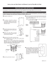
Page 20 of 69
D
REF.
A AND B
REF.
(4) 5/16" - 1/2" NON-TAPPING
REF.
E
REF.
(6) 5/16" - 3/4" NON-TAPPING
C
(4) 1-1/2" LONG SCREWS
REF.
E
(18) 5/16" - 3/4" SELF TAPPING
B
C
REF.
REF.
REF.
A
REF.
D
MIS-3014 A
Use (4) 1-1/2" Long
Louver Grille to
Outer Sleeve.
Screws to Attach
to Outer Sleeve
to Attach Inner Sleeve
Self Tapping Screws
Use (6) 3/4" Long
Unit Fan Shroud
Exhaust Sleeve to
Screws to Attach
Use (6) 3/4" Long
Use (12) 3/4" Long
to Attach Inner Sleeve
to Unit Back
Self Tapping Screws
Use (4) 1/2" Long
Screws to Attach
frame to Exhaust
Sleeve
Use (12) Field Supplied Concrete
or Wood Screws to Secure Outer
Sleeve to Structure.
outer sleeve.
IMPORTANT!
IMPORTANT!
between inner and
entire perimeter seam
seal between unit and sleeve.
IMPORTANT!
Doing so may compromise water
to not damage gasketing material.
Use care when inserting screws
Apply Caulk bead to
Apply liberal amount
of caulk to back of
flange before installing.
Pull Inner Frame
Out Until Flush
With Grille Mounting
Angle
5. Unplug heat recovery cassette on the side chosen to
access, and slide cassette out the front of the unit.
6. Remove two (2) screws securing partition on
outboard side of cassette and remove.
7. Rear drain access panels are now visible on both
right-hand and left-hand sides in rear of box.
FIGURE 11A
Unit Mounting
/