Page is loading ...

Copyright HK Instruments 2022 www.hkinstruments. Installaon version 2.0 2022
INSTALLATION
INSTRUCTIONS
Indoor air quality transmitters
Siro-MOD series
• READ THESE INSTRUCTIONS CAREFULLY BEFORE ATTEMPTING
TO INSTALL, OPERATE OR SERVICE THIS DEVICE.
• Failuretoobservesafetyinformaonandcomplywithinstrucons
canresultinPERSONALINJURY,DEATHAND/ORPROPERTY
DAMAGE.
• Toavoidelectricalshockordamagetoequipment,disconnect
powerbeforeinstallingorservicinganduseonlywiringwith
insulaonratedforfulldeviceoperangvoltage.
• Toavoidpotenalreand/orexplosiondonotuseinpotenally
ammableorexplosiveatmospheres.
• Retaintheseinstruconsforfuturereference.
• Thisproduct,wheninstalled,willbepartofanengineeredsystem
whosespecicaonsandperformancecharacteriscsarenot
designedorcontrolledbyHKInstruments.Reviewapplicaons
andnaonalandlocalcodestoassurethattheinstallaonwill
befunconalandsafe.Useonlyexperiencedandknowledgeable
technicianstoinstallthisdevice.
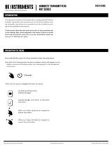
ThankyouforchoosinganHKInstrumentsSiro-MODseriesindoorair
quality transmier. The Siro-MOD series transmiers are intended for
useinbuildingautomaonsystemsintheHVAC/Rindustry.
Siro-MODisanindoorairqualitytransmierwithamoderndesign.The
transmier is available with several oponal air quality sensors. The
modulardevicecanbeequippedwithCO2concentraonandVOC(Vola-
leOrganicCompounds)measurementsoralternavelyPM(Parculate
Maer)measurementandinaddiontemperatureandhumiditymeas-
urements. It oers easy installaon and adjustment, several dierent
modeloponsandvariousoutputsignalsthatarecongurableseparately
foreachmeasurementparameter.
The Siro-MOD series devices are available with user interface that in-
cludesLCDdisplayandbuonsmakingtheconguraonofthedevice
quickandeasy.Anexternalconguraontoolisnecessaryforcommis-
sioning preparaons for Siro-MOD without user interface. Congura-
onisalsopossibleviaModbusnetwork.Siro-MODulizestheindustry
standardNDIRmeasurementprinciplewithself-calibrangABClogicTM
for CO2 measurement.
•PMconcentraontomeasuresthesizeandamountofparculates
intheindoorairforexampletoassesstheperformanceofairlters
•temperatureandhumidityinHVAC/Renvironment
SPECIFICATIONS
Performance
Measurement ranges:
CO2: 0–2000ppm/400–2000ppm
(selectableviajumper)
VOC: CO₂eq:400–2000ppm
TVOCppm:0–30.0ppm
TVOCµg/m3:0–10000µg/m3
IAQindex:1–5(UBArang)
PM1/PM2.5/PM10: 0–50μg/m³/0–500μg/m³
(selectableviajumper)
IAQindex:1-5(WHOrang)
Temperature: 0...50°C
Relavehumidity: 0–100%rH
Accuracy:
CO2: ±40ppm+3%ofreading(typical),
addional±60ppmforrstweeks
VOC*: 15%ofreading(typical)
*VOCsensoristunedfortypicalIAQMixof22VOCsas
denedbyMølhaveetal.(1997)
PM:
0…100µg/m3:
PM2.5: ±15µg/m³(at25⁰C±5⁰C)
PM1/PM10*: ±25µg/m³(at25⁰C±5⁰C)
100…1000µg/m3:
PM2.5: ±15%(at25⁰C±5⁰C)
PM1/PM10*: ±25%(at25⁰C±5⁰C)
*PM1andPM10valuesarecalculatedfromPM2.5
measurementreadingwiththedefaultparcledistribuon.
Temperature: ±0.4⁰C(typicalat20⁰C)
Relavehumidity: ±2.2%rH(typicalat20ºC,30%rH)
Technical Specicaons
Media compability:
Dryairornon-aggressivegases
Measuring units:
CO₂: ppm
VOC: CO2eq:ppm
TVOC:ppm,µg/m³
PM: PM1/PM2.5/PM10:µg/m³
Temperature: °C/°F
Relavehumidity: %rH
Measuring element:
CO2:Non-dispersiveinfrared(NDIR)
VOC:ComplementaryMetalOxide
Semiconductor(CMOS)
PM:Laser-basedlightscaeringparclesensing
Temperature:IntegratedtoCMOS
Relave humidity:Thermosetpolymercapacive
sensingelement
Calibraon:
Automacself-calibraonABCLogicTM for CO2
measurement
Environment:
Operangtemperature:0...50°C
Storagetemperature:-20...70°C
Humidity:0to95%rH,noncondensing
Physical
Dimensions: Case:95x103x30mm
(widthxheightxdepth)
Weight: 130g
Mounng:
2screwholessloed,distancec/c60mm
Materials:
Case: ABS
Protecon standard: IP20
Display (oponal)
MonochromeLCD,38x23mm
Electrical connecons:
10-pinspringloadedterminalblock
0.2...1.5mm²(16-24AWG)
Electrical
Input:24VACorVDC,±10%
Powerconsumpon:2Wmax+25mWforeach
voltageoutputor50mWforeachcurrentoutput
Outputs:
4outputs,havetoselectvoltageorcurrent
Voltageoutputs:
0 –10 V
2–10V/0–5V(oponal,displayor
conguraontoolrequired)
Currentoutput:
4–20mA(oponal)
Outputsignallimits:
Voltageoutputs:R>1kΩ
Currentoutput:R>20Ω,R<500Ω
Communicaon
Protocol:MODBUSoverSerialLine
TransmissionMode:RTU
Interface:RS485
Byteformat11bits(10bitsifparitynone):
CodingSystem:8-bitbinary
BitsperByte:
1 start bit
8databits,leastsignicantbitsentrst
1bitforparity
1stopbit
Baudrate:selectableinconguraon
Modbusaddress:1−247addressesselectablein
conguraonmenu
Conformance
Meetsrequirementsfor:
CE: UKCA:
EMC: 2014/30/EU S.I.2016/1091
RoHS: 2011/65/EU S.I.2012/3032
WEEE: 2012/19/EU S.I.2013/3113
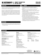
INTRODUCTION
APPLICATIONS
WARNING
Siro-MODseriesdevicesarecommonlyusedtomonitorandcontrol:
•indoorairqualityinoces,publicspaces,meengroomsand
classrooms
• CO2andVOCconcentraontoregulatedemand-controlled
venlaonandtokeeptheindoorairqualityinagoodlevel
RoHS
COMPLIANT

Copyright HK Instruments 2022 www.hkinstruments. Installaon version 2.0 2022
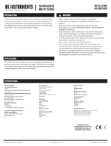
Pin header Descripon
OUT1
OUT2
OUT3
OUT4
GND
Voltage / current output selecon
•Currentoutputisanoponal
Output1
Output2
Output3
Output4
Ground
SCHEMATICS DIMENSIONAL DRAWINGS
INSTALLATION
1)Mountthedeviceinthedesiredlocaon(seestep1).
2)Routethecablesandconnectthewires(seestep2).
3)ConnectthedisplaycabletothedisplayconnectoronthePCB.(See
schemacs)
4)Thedeviceisnowreadyforconguraon.
WARNING!Applypoweronlyaerthedeviceisproperlywired.
PM SENSOR
CO₂ SENSOR
VOC SENSOR
A+
B–
24V
GND
GND
OUT1
OUT2
OUT3
OUT4
GND
OUT1
OUT2
OUT3
OUT4
21
6
5
TEMP OR
rH + TEMP
SENSOR
3
mA-MODULE
DISPLAY CONNECTOR
MODBUS-MODULE
4
Pin header Descripon
Open
Connected
Open
Connected
CO2 / PM output range selecon
400...2000ppm(CO2models)
0...2000ppm(CO2models)
0...500μg/m3(PMmodels)
0...50μg/m3(PMmodels)
Pin header Descripon
Open
Connected
Menu lock
Menulockdisabled
Menulockenabled
1
2
Connector Descripon
A+
B-
RS485 Modbus/RTU slave
DATA+
DATA-
24 V
GND
GND
Power supply
24VAC/DC±10%
Ground
Ground
3
Connector Descripon
OUT1
OUT2
OUT3
OUT4
GND
Voltage / current outputs
•Outputsengscanbemodiedfromthedisplay
menu
•Seethelidlabelforfactorydefaultsengs.
Output1
Output2
Output3
Output4
Ground
5
6
V
mA
Opening/closing the lid
1)Openthelidbypressingthecenterfromtheboomofthelidasin
thegure.
2)Closethelidbyinserngthetopofthelidintothegroovesrstand
pushingtheboomedgeasinthegure.
Pin header Descripon
Open
Connected
Modbus terminaon
Notterminated
Terminated
4

Copyright HK Instruments 2022 www.hkinstruments. Installaon version 2.0 2022
Figure 2a - Roung the cables
Figure 2b - Wiring diagram: Power input & signal output
Figure 1a - Surface mounng
Figure 1b - Mounng orientaon
YES NO NO
1)Routethecablesthroughtheopeninginthebackplateorfor
surfacewiringselectaknockoutontheboomofthewallplate,
asshowninFigure2a.
2)ConnectthewiresasshowninFigure2band2c.
CAUTION!
•ForCEcompliance,aproperlygroundedshieldingcableisrequired.
•Usecopperwireonly.Insulateorwirenutallunusedleads.
•Careshouldbeusedtoavoidelectrostacdischargetothedevice.
•Thisunithasconguraonjumpers.Youmayneedtorecongure
thisdeviceforyourapplicaon.
STEP 2: WIRING DIAGRAMSSTEP 1: MOUNTING THE DEVICE
1)Selectamounnglocaononthewallat1.2–1.8m(4–6)above
theoorandatleast50cm(20in)fromtheadjacentwall.Do
notblockdeviceairventsfromanydireconandleaveatleast
20cm(8in)gaptootherdevices.Locatetheunitinanareawith
goodvenlaonandanaveragetemperature,whereitwillbe
responsivetochangestotheroomcondions.TheSiro-MOD
shouldbemountedonaatsurface.
DonotlocatetheSiro-MODwhereitcanbeaectedby:
•Directsunlight
•Drasordeadareasbehinddoors
•Radiantheatfromappliances
•Concealedpipesorchimneys
•Outsidewallsorunheated/uncooledareas
2)Usethedeviceasatemplateandmarkthescrewholes.
3)Mountthewallplatewithscrews.
CAUTION!Incorrectinstallaonmaycauseashiinmeasurements.
Figure 1c - Mounng locaon
120 cm (4 ft)
180 cm (6 ft)
≥
50 cm (20 in)
≥ 20 cm (8 in)
≥ 20 cm (8 in)
NOTE! When using long connecon wires it may be necessary to use a
separateGNDwireforvoltageoutputcurrenttopreventmeasurementdis-
toron.TheneedforanextraGNDwiredependsonthecrossseconand
lengthoftheusedconneconwires.Iflongand/orsmallcrossseconwires
areused,supplycurrentandwireresistancemaygenerateavoltagedropin
thecommonGNDwireresulnginadistortedoutputmeasurement.
When usingAC power supply, makesure thatthe groundpotenal ofthe
signalisthesameasthegroundpotenalofthesupplyvoltagetoavoidshort
circuitthroughtheaddionalGNDwire.
It is recommended to use shielded twisted pair cable for modbus cabling.
Thecableshieldmustbeearthedonlyinonepoint,normally,attheendof
themaincable.
OUT1
OUT2
OUT3
OUT4
GND
A+
B–
24V
GND
GND
0-10V/2-10V/0-5V/4-20mA
0-10V/2-10V/0-5V/4-20mA
0-10V/2-10V/0-5V/4-20mA
0-10V/2-10V/0-5V/4-20mA
+
Figure 2c - Wiring diagram: Extra GND wire
OUT1
OUT2
OUT3
OUT4
GND
A+
B–
24V
GND
GND
V
V
V
V
0-10V/2-10V/0-5V/4-20mA
0-10V/2-10V/0-5V/4-20mA
0-10V/2-10V/0-5V/4-20mA
0-10V/2-10V/0-5V/4-20mA
+
STEP 3: CONFIGURATION
ConguraonoftheSiro-MODseriesdeviceconsistsof:
1)Conguringthejumpers(seestep4).
2)Conguraonmenuopons.
(Display(-D)orconguraontoolrequired.Seetheusermanual
forfurtherdetails.)

Copyright HK Instruments 2022 www.hkinstruments. Installaon version 2.0 2022
1)Conguraonoftheoutputmodes:
Selecttheoutputmode,current(4–20mA)(oponal)orvoltage(0–10V)
foreachoutput(1-4)byinstallingjumpersasshowninFigure4.
Onadisplayversionofthedevice,theoutputscalecanbechangedviathe
conguraonmenu.Anexternalconguraontoolisavailablefordevices
withoutuserinterface.
First,selecttheoutputmodebyjumper,thenselecttheoutputscale(4–
20mA(oponal)/0–10V/2–10V/0–5V)viatheconguraonmenu.
Pleaseseetheusermanualformoredetails.
Thesellerisobligatedtoprovideawarrantyofveyearsforthedeliveredgoods
regardingmaterialandmanufacturing.Thewarrantyperiodisconsideredtostart
onthedeliverydateoftheproduct.Ifadefectinrawmaterialsoraproducon
awisfound,thesellerisobligated,whentheproductissenttothesellerwithout
delayorbeforeexpiraonofthewarranty,toamendthemistakeathis/herdis-
creoneitherbyrepairingthedefecveproductorbydeliveringfreeofcharge
tothebuyeranewawlessproductandsendingittothebuyer.Deliverycosts
fortherepairunderwarrantywillbepaidbythebuyerandthereturncostsbythe
seller.Thewarrantydoes notcomprisedamagescausedbyaccident,lightning,
oodorothernaturalphenomenon,normalwearandtear,improperorcareless
handling,abnormaluse,overloading,improperstorage,incorrectcareorrecon-
strucon,orchangesandinstallaonworknotdonebytheseller.Theselecon
of materials fordevices prone to corrosion is the buyer’sresponsibility,unless
otherwiseislegallyagreedupon.Shouldthemanufactureralterthestructureof
the device, the seller is not obligated to make comparable changes to devices
alreadypurchased.Appealingforwarrantyrequiresthatthebuyerhascorrectly
fullled his/herduesarisenfromthedeliveryandstatedinthecontract.The
seller will give a new warranty for goods that have been replaced or repaired
withinthewarranty,howeveronlytotheexpiraonoftheoriginalproduct’swar-
rantyme.Thewarrantyincludestherepairofadefecvepartordevice,orif
needed,anewpartordevice,butnotinstallaonorexchangecosts.Underno
circumstanceisthesellerliablefordamagescompensaonforindirectdamage.
Figure 4
STEP 4: Jumper settings
RECYCLING/DISPOSAL
The parts le over from installaon should be re-
cycledaccordingtoyourlocalinstrucons.Decom-
missioned devices should be taken to a recycling
sitethatspecializesinelectronicwaste.
WARRANTY POLICY
Figure 3 - Jumper installaon
A+
B–
24V
GND
GND
OUT1
OUT2
OUT3
OUT4
GND
OUT1
OUT2
OUT3
OUT4
3
12
4
OUT1
OUT2
OUT3
OUT4
V
mA
NOTE! When using mA output, do not use Vout scalings from the menu.
Using2-10Voutputinsomeapplicaonsitiscricaltoknowimmidiatelyif
thewireisbrokenorthedeviceisdamaged.Inthesecases,a2-10voltage
outputisrecommended.
2)OutputrangeseleconwithCO2-andPM-models:
Installthejumper1(gure3)tochangeoutputrange.Thisfeatureis
intendedtouseonlyondeviceswithoutdisplay.Onadisplayversionof
thedevice,theoutputrangecanbeselectedviatheconguraonmenu.
Pleaseseetheusermanualformoredetails.
Pin header Descripon
Open
Connected
Open
Connected
CO2 / PM output range selecon
400...2000ppm(CO2models)
0...2000ppm(CO2models)
0...500μg/m3(PMmodels)
0...50μg/m3(PMmodels)
1
3)Lockingthedisplay:
Installthejumper2(gure3)tolockthedisplaytopreventaccesstothecon-
guraonmenuaerinstallaoniscompleted.
4)Modbusterminaon:
Installajumper4(gure3)toterminateModbus.
In order toavoidsignalreecons,Modbus terminaon jumper must be
installedincaseifthedeviceisthelastoneofthebus.
Modbus registers continued
Register Parameter descripon Data type Min value Max value Range
4x0001 OsetCO2 16bit -200 200 -200..200ppm
4x0002 OsetHumidity 16bit -10 0 100 -10.0..10.0%
4x0003 OsetCelsius*1 16bit -50 50 -5.0..5.0°C
4x0004 OsetFahrenheit*1 16bit -90 90 -9.0..9.0°F
4x0005 OsetTVOCppm 16bit -300 300 -3.00..3.00ppm
4x0006 OsetTVOCug/m3 16bit -1000 1000 -1000..1000ug/m3
4x0007 OsetCO2EQ 16bit -20 0 200 -200..200ppm
4x0008 OsetPM 16bit 30 200 0.3..2.0coecient
4x0009 Backlightintensity 16bit 0100 0..100%
4x0010 DisplayCelsius*2 16bit 06 Posionnumber,0=notused
4x0011 DisplayFahrenheit*2 16bit 06 Posionnumber,0=notused
4x0012 DisplayHumidity 16bit 06 Posionnumber,0=notused
4x0013 DisplayCO2 16bit 06 Posionnumber,0=notused
4x0014 DisplayCO2 EQ 16bit 06 Posionnumber,0=notused
4x0015 DisplayPM2.5hour 16bit 06 Posionnumber,0=notused
4x0016 DisplayPM10hour 16bit 06 Posionnumber,0=notused
4x0017 DisplayIAQ 16bit 06 Posionnumber,0=notused
Register Parameter descripon Data type Min value Max value Range
3x0001 Programversion 16bit 19999 0.01..99.99
3x0002 CO2reading 16bit 02500 0..2500ppm
3x0003 rHreading 16bit 01000 0.0..100.0%
3x0004 TemperatureCelsius 16bit 0500 0.0..50.0°C
3x0005 TemperatureFahrenheit 16bit 320 1220 32.0..122.0°F
3x0006 TVOCppmreading 16bit 03200 0.00..32.00ppm
3x0007 TVOCug/m3reading 16bit 010000 0..10000ug/m3
3x0008 CO2_eqreading 16bit 012000 0..12000ppm
3x0009 IAQreadingTVOC 16bit 15 1..5IAQindex
3x0010 IAQreadingPM 16bit 15 1..5IAQindex
3x0011
3x0012 PM1reading 16bit 01000 0..1000ug/m3
3x0013 PM2.5reading 16bit 01000 0..1000ug/m3
3x0 014 PM10reading 16bit 01000 0..1000ug/m3
3x0015 PM2.51haverage 16bit 010000 0.0..1000.0ug/m3
3x0016 PM2.524haverage 16bit 010000 0.0..1000.0ug/m3
3x0017 PM101haverage 16bit 010000 0.0..1000.0ug/m3
3x0018 PM1024haverage 16bit 010000 0.0..1000.0ug/m3
3x0 019
3x0020 Error status 16bit 065535 Seetablebelow
STEP 5: Modbus registers
Bit0temperaturesensordetected, 0=notdetected,1=detected
Bit1humiditysensordetected, 0=notdetected,1=detected
Bit2co2sensordetected, 0=notdetected,1=detected
Bit3vocsensordetected, 0=notdetected,1=detected
Bit4pmsensordetected, 0=notdetected,1=detected
Bit5displaymoduledetected, 0=notdetected,1=detected
Bit6current(mA)moduledetected, 0=notdetected,1=detected
Bit8sensorwarmup 0=normaloperaon,1=warmup
Bit9rhtstatus 0=normaloperaon,>0readingerror
Bit10CO2status 0=normaloperaon,>0readingerror
Bit11pmstatus 0=normaloperaon,>0readingerror
Bit12vocstatus 0=normaloperaon,>0readingerror
3x0020 Error status bits
Funcon code 03 - Read holding registers, Funcon code 06 - Write single register,
Funcon code 16 - Write mulple registers, Broadcast supported with address 0
Funcon code 04 - Read input register
*1=CelsiusandFahrenheitlimitsareinterdependent,andthusachange inonelimitofameas-
urementwillalsochangethelimitsoftheothermeasurement.UseFunconcode06(writesingle
register)forCelsiusorFahrenheit.
*2=UseFunconcode16(writemulpleregisters)fordisplayconguraon.Validvalue(0/1...6)
neededforalldisplayconguraonregisters.(seeSiroUserGuideSTEP1.1:Displayview)
/