Copyright HK Instruments 2022 www.hkinstruments. Installaon version 8.0 2022
The seller is obligated to provide a warranty of ve years for the delivered
goods regarding material andmanufacturing. The warranty period is consid-
eredtostartonthedeliverydateoftheproduct.Ifadefectinrawmaterials
oraproduconawisfound,thesellerisobligated,whentheproductissent
tothesellerwithoutdelayorbeforeexpiraonofthewarranty,toamendthe
mistake athis/her discreon either byrepairing thedefecve product or by
deliveringfreeofchargetothebuyeranewawlessproductandsendingitto
thebuyer.Deliverycostsfortherepairunderwarrantywillbepaidbythebuyer
andthereturncostsbytheseller.Thewarrantydoesnotcomprisedamages
causedbyaccident,lightning,oodorothernaturalphenomenon,normalwear
andtear,improperorcarelesshandling,abnormaluse,overloading,improper
storage,incorrectcareorreconstrucon,orchangesandinstallaonworknot
donebytheseller.Theseleconofmaterialsfordevicespronetocorrosionis
thebuyer’sresponsibility,unlessotherwiseislegallyagreedupon.Shouldthe
manufactureralterthestructureofthedevice,thesellerisnotobligatedto
makecomparablechangestodevicesalreadypurchased.Appealingforwar-
rantyrequiresthatthebuyerhascorrectlyfullledhis/herduesarisenfrom
thedeliveryandstatedinthecontract.Thesellerwillgiveanewwarrantyfor
goodsthathavebeenreplacedorrepairedwithinthewarranty,howeveronly
totheexpiraonoftheoriginalproduct’swarrantyme.Thewarrantyincludes
therepairofadefecvepartordevice,orifneeded,anewpartordevice,but
notinstallaonorexchangecosts.Undernocircumstanceisthesellerliablefor
damagescompensaonforindirectdamage.
Register Parameter descripon Data Typ e Value Range
4x0001 ParameterforP-controller 16bit 0...3 0=CO2,1=rH,2=TE,3=MAX
4x0002 CO2hIghlimit 16bit 500...2000 500...2000ppm
4x0003 CO2lowlimit 16bit 0...1900 0...1900ppm
4x0004 rHhighlimit 16bit 100...1000 10.0...100.0%
4x0005 rHlowlimit 16bit 0...900 0.0...90.0%
4x0006 TEhighlimit 16bit 50...500 5.0...50.0°C
4x0007 TElowlimit 16bit 0...450 0...45.0°C
4x0008 Parameter for relay 16bit 0...3 0=CO2,1=rH,2=TE,(3=O)
4x0009 CO2relayon 16bit 500...1950 500...1950ppm
4x0010 CO2relayo 16bit 450...1900 450...1900ppm
4x0011 rH relay on 16bit 15...990 1.5...99.0%
4x0012 rHrelayo 16bit 10...985 1.0...98.5%
4x0013 TE relay on 16bit 15...490 1.5...49.0°C
4x0014 TErelayo 16bit 10...485 1.0...48.5°C
4x0015 CO2Oset 16bit -200…200 -200…200ppm
4x0016 RHOset 16bit -100…100 -10.0…10.0%rH
4x0017 TEOset 16bit -50…50 -5.0…5.0°C
Funconcode03-Readinputholdingregister
Funconcode04-Readinputregister
Register Parameter descripon Data Typ e Value Range
3x0001 ParameterforP-controller 16bit 0...3 0=CO2,1=rH,2=TE,3=MAX
3x0002 CO2reading 16bit 0...2000 0...2000ppm
3x0003 rHreading 16bit 0...1000 0,0...100.0%
3x0004 Temp.reading 16bit 0...500 0.0...50.0°C
3x0005 CO2highlimit 16bit 500...2000 500...2000ppm
3x0006 CO2lowlimit 16bit 0...1900 0...1900ppm
3x0007 rHhighlimit 16bit 100...1000 10.0...100.0%
3x0008 rHlowlimit 16bit 0...900 0.0...90.0%
3x0009 TEhighlimit 16bit 50...500 5.0...50.0°C
3x0010 TElowlimit 16bit 0...450 0...45.0°C
3x0011 Parameter for relay 16bit 0...3 0=CO2,1=rH,2=TE,(3=O)
3x0012 CO2relayon 16bit 500...1950 500...1950ppm
3x0013 CO2relayo 16bit 450...1900 450...1900ppm
3x0 014 rH relay on 16bit 15...990 1.5...99.0%
3x0015 rHrelayo 16bit 10...985 1.0...98,5%
3x0016 TE relay on 16bit 15...490 1.5...49.0°C
3x0017 TErelayo 16bit 10...485 1.0...48.5°C
3x0018 CO2Oset 16bit -200…200 -200…200ppm
3x0 019 RHOset 16bit -100…100 -10.0…10.0%rH
3x0020 TEOset 16bit -50…50 -5.0…5.0°C
3x0021 Programversion 16bit 10…9999 1.0…999.9
MODBUS REGISTERS CONTINUED
Funconcode16-Writemulpleregisters
Register Parameter descripon Data Typ e Value Range
4x0001 ParameterforP-controller 16bit 0...3 0=CO2,1=rH,2=TE,3=MAX
4x0002 CO2hIghlimit 16bit 500...2000 500...2000ppm
4x0003 CO2lowlimit 16bit 0...1900 0...1900ppm
4x0004 rHhighlimit 16bit 100...1000 10.0...100.0%
4x0005 rHlowlimit 16bit 0...900 0.0...90.0%
4x0006 TEhighlimit 16bit 50...500 5.0...50.0°C
4x0007 TElowlimit 16bit 0...450 0...45.0°C
4x0008 Parameter for relay 16bit 0...3 0=CO2,1=rH,2=TE,(3=O)
4x0009 CO2relayon 16bit 500...1950 500...1950ppm
4x0010 CO2relayo 16bit 450...1900 450...1900ppm
4x0011 rH relay on 16bit 15...990 1.5...99.0%
4x0012 rHrelayo 16bit 10...985 1.0...98.5%
4x0013 TE relay on 16bit 15...490 1.5...49.0°C
4x0014 TErelayo 16bit 10...485 1.0...48.5°C
4x0015 CO2Oset 16bit -200…200 -200…200ppm
4x0016 RHOset 16bit -100…100 -10.0…10.0%rH
4x0017 TEOset 16bit -50…50 -5.0…5.0°C
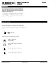
RECYCLING/DISPOSAL
The parts le over from installaon should be
recycled according to your local instrucons.
Decommissioned devices should be taken to a
recyclingsitethatspecializesinelectronicwaste.
WARRANTY POLICY
Register Parameter descripon Data Typ e Value Range
1x0001 Relay status Bit0 0...1 0=O-1=On
1x0002 Relaytrend Bit0 0...1 0=Increasing,1=Decreasing
1x0003 Timer status Bit0 0...1 0=O-1=On
Funconcode02-Readinputstatus
Funconcode06-Writesingleregister
Register Parameter descripon Data Typ e Value Range
4x0001 ParameterforP-controller 16bit 0...3 0=CO2,1=rH,2=TE,3=MAX
4x0002 CO2hIghlimit 16bit 500...2000 500...2000ppm
4x0003 CO2lowlimit 16bit 0...1900 0...1900ppm
4x0004 rHhighlimit 16bit 100...1000 10.0...100.0%
4x0005 rHlowlimit 16bit 0...900 0.0...90.0%
4x0006 TEhighlimit 16bit 50...500 5.0...50.0°C
4x0007 TElowlimit 16bit 0...450 0...45.0°C
4x0008 Parameter for relay 16bit 0...3 0=CO2,1=rH,2=TE,(3=O)
4x0009 CO2relayon 16bit 500...1950 500...1950ppm
4x0010 CO2relayo 16bit 450...1900 450...1900ppm
4x0011 rH relay on 16bit 15...990 1.5...99.0%
4x0012 rHrelayo 16bit 10...985 1.0...98.5%
4x0013 TE relay on 16bit 15...490 1.5...49.0°C
4x0014 TErelayo 16bit 10...485 1.0...48.5°C
4x0015 CO2Oset 16bit -200…200 -200…200ppm
4x0016 RHOset 16bit -100…100 -10.0…10.0%rH
4x0017 TEOset 16bit -50…50 -5.0…5.0°C
STEP 5: MODBUS REGISTERS
FunconsforModbuscommunicaon:
Funcon Code Descripon
01 Readcoilstatus
02 Readinputstatus
03 Readholdingregisters
04 Readinputregisters
05 Forcesinglecoil
06 Presetsingleregister
07 Readexceponstatus
15 Forcemulplecoils
16 Presetmulpleregisters
17 ReportslaveID
Funconcode05-Writesinglecoil
Register Parameter descripon Data Typ e Value Range
0x0001 Relaytrend Bit0 0...1 0=Increasing,1=Decreasing