Workrite Ergonomics Ascent 2 Digital Switch Installation guide

Type
Installation guide
IMPORTANT: You must RESET the switch prior to use.
1 of 5 ISE | (800) 463-7731 www.ise-group.com
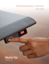
ASCENT 2 DIGITAL READOUT MEMORY SWITCH
USER GUIDE
ASCENT 2 DIGITAL READOUT MEMORY SWITCH INTERFACE
The Ascent 2 Digital Readout Memory Switch has a number of features that customize to individual users and work conditions.
Please read the instruction completely before you begin.
The Ascent 2 Digital Readout Memory Switch has a digital display and seven buttons.
THE DIGITAL DISPLAY
The display has three digits. The table height is shown in inches and the display will show the height to within 0.1 of an inch.
THE BUTTONS
HEIGHT CONTROL UP AND DOWN
The UP and DOWN buttons are used for moving the table up and down when the user presses the button.
MEMORY PRE-SETS
Convenient pre-sets for up to four heights.
SAVE SETTINGS TO MEMORY
Used to commit a setting to memory.
Memory Pre-Sets, 1–4
Save Setting to Memory
Height Control
Up and Down
Display
Model # -DRMS
2 of 5 ISE | (800) 463-7731 www.ise-group.com
INITIALIZING OR RESETTING
IMPORTANT: You must INITIALIZE the switch prior to use!
You will need to "initialize" your table aer initial installation or "reset" aer troubleshooting. Follow these steps to initialize/
reset your Ascent 2 Workcenter.
Step User input Control indication
1. Press the DOWN button until the workcenter
reaches the lowest position
Display shows the current height until you reach the lowest point:
2. Press the DOWN button AGAIN and keep it
pressed for about TEN seconds until you see
"RST" on the display
3. Press and hold the DOWN button a THIRD TIME
until the desk lowers a little bit more, slightly
rises and stops.
blinks
4. Release the DOWN button
The display has been initialized or reset.
PROGRAMMING MEMORY PRE-SETS
The Ascent 2 Digital Readout Memory Switch enables up to four pre-set memory positions. Programming the pre-sets has three
steps:
SAVING A MEMORY PRE-SET HEIGHT
Step User input Control indication
1. Move the table to the desired height Display shows the current height
2. Press the MEMORY button "M"Display shows
3. Press one of the four pre-set Height Buttons
(1,2,3,4)
Display shows the current height
USE
• Make sure no obstacles are in the desks path
• Make sure the work surface is not touching any walls
• Make sure all cords are the appropriate length to accommodate the change in height
MOVING USING THE ARROWS
The desk base can be adjusted by pressing and holding either the UP or DOWN button until the desired height is reached.
MOVING TO A PRE-SET HEIGHT
Step User input Control indication
1. Press and hold the desired memory button Display shows the current height during movement
The desktop will move until it reaches the saved position. If you release the key before the saved position is reached, the
desktop will stop and the saved desktop position will not be reached.
3 of 5 ISE | (800) 463-7731 www.ise-group.com
SETTING CUSTOM HEIGHT LIMITS
The custom height limit feature protects the workcenter from colliding with items placed above or below the worksurface such
as overhanging shelves or pedestals below. This base is designed to go to its minimum and maximum heights, allowing for the
widest possible range. If you prefer to change the settings to a more narrow range, make sure the power is ON and a number
reads in the LED display and follow these steps:
SET LOWER LIMIT
Step User input Control indication
1. Press the UP or DOWN button to move your
workcenter to the desired lower limit. Leave a 1"
minimum space between the worksurface and the
object below the workcenter for safety.
Make sure the DOWN button was the last button
you pushed.
Display shows the current height during movement
2. Press and hold the “M” button until the LED display
flashes “S -” once and let go of the button Display flashes
3. Press and release the “M” button 2 more times in
quick succession The LED display will change to on the third
push and then automatically return to the selected
height. The new lower limit is now set.
SET UPPER LIMIT
Step User input Control indication
1. Press the UP or DOWN button to move your
workcenter to the desired upper limit. Leave a 1"
minimum space between the worksurface and the
object above the workcenter for safety.
Make sure the UP button was the last button you
pushed.
Display shows the current height during movement
2. Press and hold the “M” button until the LED display
flashes “S -” once and let go of the button Display flashes
3. Press and release the “M” button 2 more times in
quick succession The LED display will change to on the third
push and then automatically return to the selected
height. The new upper limit is now set.
REMOVE LIMITS
Step User input Control indication
1. Use the UP or DOWN button to move the desk to any
new position.
Display shows the current height during movement
2. Press and hold the “M” button until the LED display
flashes “S -” once and let go of the button Display flashes
3. Press and release the “M” button in quick succession The LED display will change to (ignore any
interim readings)
Aer a few seconds, the display automatically will
change back to the numbered height position. The
upper and lower limits are now removed.
NOTES:
Aer the upper and lower limits are set, the previous memory positions (1, 2, 3, 4) may be outside the new range of movement.
If so, simply reset the memory positions.
If you attempt to revise a previously set upper or lower limit and it is outside of the existing range, you will need to remove the
previously set upper/lower limits first.
4 of 5 ISE | (800) 463-7731 www.ise-group.com
CHANGING THE HEIGHT ON THE DISPLAY
CHANGING THE RETRACTED HEIGHT
There may be a need to reset or change the display height setting. If you add casters, for example, your workcenter is about 1.5"
higher. If you have a low profile worksurface, then your height might be lower by .5". You will need a tape measure to accurately
change the display.
Step User input Control indication
1. Press the DOWN button until the workcenter reaches
the lowest position
Display shows the current height until you reach the
lowest height:
Measure the height from the floor to the top of your worksurface for the correct height to be entered in STEP 4
2. Press and hold the DOWN button again until the LED
display reads “RST”
3. Press the MEMORY button for about 5 seconds* Display flashes five times then height appears
4. Press UP
Press DOWN
Display number increases by 0.1
Display number decreases by 0.1
Press 1
Press 2
Display number increases by 1.0
Display number decreases by 1.0
Press 3
Press 4
Display number increases by 10.0
Display number decreases by 10.0
Once the new value is displayed, wait about 5 seconds and the display will return to “RST”
5. Press the DOWN button again until the desk lowers a
little bit more, slightly rises and stops
The display is now set to the correct height
* If the display returns to “RST” before the next step is taken, repeat this step .
The display has been corrected and custom user settings are retained. Note: the LED display has a 0.1 tolerance.
TROUBLESHOOTING ERROR CODES
The Ascent 2 Digital Readout Memory Switch includes a diagnostic code system using the digital readout that allows our service
team to easily identify service requirements for your workcenter. In the unlikely event that an error code appears, here’s what to
do:
The most frequent error codes are E36, E37 and E38. This indicates that a motor cable is disconnected from the control box.
Check the connections for all cables at the control box to make sure everything is plugged in correctly.
If another error code other than E36, E37 or E38 appear and the workcenter will not respond to other button pushes to move up
or down here is what to do:
Write the code(s) down. Call Workrite Field Service at (800) 959-9675 then press 2 for Technical Support or e-mail to:
fieldservice@workriteergo.com
If e-mailing, give full description of error code and complete contact information including phone number and extension so our
team may call you back to resolve your error code and get your workcenter up and running.
Error Code Error summary Description
E0 1
M1 overcurrent protection Switch shows E01. All Columns Stop Working. Press any key shows RST. System needs reset.
E02
M2 overcurrent protection Switch shows E02. All Columns Stop Working. Press any key shows RST. System needs reset.
E03
M3 overcurrent protection Switch shows E03. All Columns Stop Working. Press any key shows RST. System needs reset.
E04
M4 overcurrent protection Switch shows E04. All Columns Stop Working. Press any key shows RST. System needs reset.
E05
M5 overcurrent protection Switch shows E05. All Columns Stop Working. Press any key shows RST. System needs reset.
E06
M6 overcurrent protection Switch shows E06. All Columns Stop Working. Press any key shows RST. System needs reset.
E07
M1 Hall Error Switch shows E07. All Columns Stop Working. Press any key shows RST. System needs reset.
E08
M2 Hall Error Switch shows E08. All Columns Stop Working. Press any key shows RST. System needs reset.
E09
M3 Hall Error Switch shows E09. All Columns Stop Working. Press any key shows RST. System needs reset.
E10
M4 Hall Error Switch shows E10. All Columns Stop Working. Press any key shows RST. System needs reset.
E11
M5 Hall Error Switch shows E11. All Columns Stop Working. Press any key shows RST. System needs reset.
E 12
M6 Hall Error Switch shows E12. All Columns Stop Working. Press any key shows RST. System needs reset.
E 13
Communication interrupt
between controller A and B
Switch shows E13. All Columns Stop Working. Press any key shows RST. System needs reset.
H0 1
Over heat protection/Duty
cycle protection
Switch shows H01. All Columns Stop Working. Pressing any key has no eect. Switch shows
current height aer 16 minute rest.
Remark:
1- 6 li columns synchro working by 2 control boxes, the main control box is "A", and the other one is "B"
2- M1, M2, M3 controlled by single control box or "A" control box; M4, M5 M6 controlled by control box "B"
3- Overcurrent protection trigger condition: (1) over loaded when columns liing up (2) columns still running when reach
highest/lowest position (3) mechanical fault , electric fault
4- Hall error trigger condition: (1) +5V/GND/H1/H2/ wire fault (2) motor core fault, no signal or few signal output
5- Communication interrupt between A and B trigger condition: (1) controller B or controller A_SCI2 fault (2)connection
between controller A and B fault
6- Over heat trigger condition: Too high temperature for heating elements
7- Duty cycle trigger condition: Continuously working more than 4 minutes, needs to rest 16 minutes
5 of 5 ISE | (800) 463-7731 www.ise-group.com
#1500349 Rev A
  • Page 1 1
  • Page 2 2
  • Page 3 3
  • Page 4 4
  • Page 5 5

Workrite Ergonomics Ascent 2 Digital Switch Installation guide

Type
Installation guide

Ask a question and I''ll find the answer in the document

Finding information in a document is now easier with AI