Page is loading ...

Workrite Ergonomics | 800.959.9675 www.workriteergo.com 1 of 18
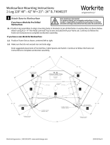
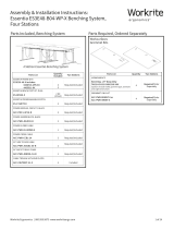
Worksurfaces
Grommet Kits
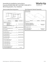
Parts Included, Benching System Parts Required, Ordered Separately
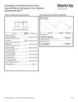
Assembly & Installation Instructions:
Fundamentals Benching System
FDEX 60-B02-WP; FDLX 60-B02-WP; FDEX 72-B02-WP; FDLX 72-B02-WP
Parts List Quantity
Included Two Stations
FUNDAMENTALS FRAME SETS
FDEX/FDLX 60-72-BXX-WPXX includes: Required/Included
FUNDAMENTALS BENCH FOOT KIT, DUAL
SE-BFK48-X 1 Kit
(2 Feet) Required/Included
FUNDAMENTALS PROGRAMMABLE SWITCH
PROSWITCH 2 Required/Included
POWER MODULE, CIRCUIT 1, BLACK
ACC-PMC1-4P2U-B 2 Required/Included
POWER JUMPER BLOCK, BLACK
ACC-PWR-JBLOCK-B 1 Required/Included
POWER IN FEED CABLE
ACC-PWR-IN-HDWR-B 1 Required/Included
POWER CROSS CABLE
ACC-PWR-CCBL-36 or ACC-PWR-CCBL-48 1 Required/Included
54" BACK TO BACK CABLE
ACC-PWR-JBBCBL-54-B 1 Required/Included
CABLE TROUGH WITH END PLATES
ACC-CBLTRKIT-53-X or ACC-CBLTRKIT-65-X
2 Included
Parts List Quantity Two Stations
WORKSURFACE
Benching - 29" Deep Only
T5829-XX-B3-XXXXXXX-XXX, or
T7029-XX-B3-XXXXXXX-XXX
(Options include width, grommet type, laminate
and edge band colors)
2Required/Order
Separately
GROMMET ONLY KIT
ACC-PWR-REMNT-X or
ACC-PWR-INMNT-X 2Required/Order
Separately
Fundamentals Benching System

2 of 18 Workrite Ergonomics | 800.959.9675 www.workriteergo.com
Workcenters
Trough
Benching
Foot Kit
Inlay Power
Grommets
Back to Back
Cable
Power In Feed
Recessed Power
Table of Contents
Step Page
You will assemble TWO complete Benching Workcenters joined by a pair of Benching
Feet.
Build Workcenters Page 6
FDEX/FDLX 60-72-BXX
Add Power & Recessed Mount Kit Page 10
ACC-PMC1-4P2U-B, ACC-PWR-JBLOCK-B,
ACC-PWR-CCBL-36 or ACC-PWR-CCBL-48, ACC-PWR-REMNT-X
Add Trough Page 13
ACC-CBLTRKIT-53-X or ACC-CBLTRKIT-65-X
Add Benching Foot Kit Page 14
SE-BF-CONKIT
Add Inlay Mount Kit (if applicable) Page 15
ACC-PWR-INMNT-X
Install Grommets Page 15
ACC-PWR-REMNT-X or ACC-PWR-INMNT-X
Connect Back to Back Cable Page 16
ACC-PWR-JBBCBL-54-B
Connect Power Page 16
ACC-PWR-IN-HDWR-B
Adjust Glides Page 17
Initialize Legs Page 17

Workrite Ergonomics | 800.959.9675 www.workriteergo.com 3 of 18
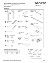
Parts Included
E Long Bracket
Qty: 4
N Leg Cable,
2 meter
Qty: 4
O Power Cable
Qty: 2
K Cable Spool
Qty: 2
M " Cable Loops
Qty: 20
A Control Leg
(Right)
Qty: 2 Companion
Leg (Le)
Qty: 2 B Short Bracket
Qty: 4
I 4 mm Allen Wrench
Qty: 1
H Foot Glide
Qty: 6
C Le End Bracket
Qty: 2
D Right End Bracket
Qty: 2
F #M6 × 14 mm Flat Head Cap
Screw
Qty: 24
L #8 × ⅝" Pan Head Screw
Qty: 24
G #12 × ¾" Pan Head Laminate
Top Screw
Qty: 50
Frame Assembly Parts:
Fundamentals Benching System
FDEX 60-B02-WP; FDLX 60-B02-WP; FDEX 72-B02-WP; FDLX 72-B02-WP
J Short Power Cord
Qty: 4
Q Programmable Switch
Qty: 2
R Top/Worksurface Trim Kit
Circuit 1 Power Module
Qty: 2
#10 × 3/4" Phillips Head
Screw - Black
Qty: 4
Jumper Block
Qty: 1
Back To Back Jumper
Cable, 54" - Black
Qty: 1
Power Cross Cable-Silver
24", 36" or 48"
Qty: 1
#8 × 3/4" Phillips Head
Screw - Black
Qty: 2
Cable Loop
Qty: 2
Power In Cable, 96" Hardwire,
Dual Circuit
Qty: 1
Installation Manual
Qty: 1
P Power Supply
Qty: 2

4 of 18 Workrite Ergonomics | 800.959.9675 www.workriteergo.com
IMPORTANT NOTE!
You must complete initialization (Step 19)/(Step 20) at the end of
assembly or your workcenter WILL NOT FUNCTION PROPERLY.
WARNING: Maximum loading of table assembly is 125 lb. (56 kg.). Maximum load includes the
weight of the table top itself, any equipment placed upon it, and any equipment suspended or hanging under it. Loading
should be evenly distributed over table surfaces. “Payload Capacity” is the Workrite Ergonomics recommended maximum
loading which includes the Workrite sourced worksurface.
Fundamentals 2-leg
V = 120VAC, 60Hz / 2.5 A maximum
IMPORTANT SAFETY INSTRUCTIONS:
When using an electrical furnishing, basic precautions should always be followed, including the following:
Read all instructions before using this Sierra Workcenter.
SAVE THESE INSTRUCTIONS
WARNING: To reduce the risk of burns, fire, electric shock, or injury to persons:
•Unplug from outlet before putting on or taking o parts, always unplug this Sierra Workcenter from the electrical outlet
before cleaning.
•Close supervision is necessary when this furnishing is used by, or near children, invalids, or disabled persons.
•Use this furnishing only for its intended use as described in these instructions. Do not use attachments not
recommended by the manufacturer.
•Never operate this furnishing if it has a damaged cord or plug, if it is not working properly, if it has been dropped or
damaged, or dropped into water. Return the furnishing to a service center for examination and repair.
•Keep the cord away from heated surfaces.
•Do not use outdoors.
•Do not operate where aerosol (spray) products are being used or where oxygen is being administered.
FOR COMMERCIAL USE ONLY
✓
THIS ELECTRICAL SYSTEM IS UL CERTIFIED BY ETL FOR USE AS DESCRIBED BELOW. ALL SPECIFICATIONS
AND WARNINGS MUST BE FOLLOWED CLOSELY IN ASSEMBLY AND USE OF THIS SYSTEM.
CAUTIONS AND WARNINGS
WARNING: FAILURE TO FOLLOW CAUTIONS AND WARNINGS BELOW COULD RESULT IN ELECTRICAL SHOCK,
FIRE, PROPERTY DAMAGE, PERSONAL INJURY, OR DEATH.
CAUTIONS:
•Read Instructions: Read all warnings and installation instructions before installing and use
•Retain Instructions: Retain this instruction sheet for future use
•Wet Environment
· This system is designed for use indoors in a dry environment
· Never use this system in a wet environment
· Never allow liquids of any type to spill into the electrical system
•Follow Warnings: Read and follow all warnings and directions in this instruction sheet and marked on the components
of the system
•Service
· There are no serviceable parts contained in this system
· Do not open and or modify any parts used in this electrical system

Workrite Ergonomics | 800.959.9675 www.workriteergo.com 5 of 18
✓ Verify that you have all the tools needed for the assembly
You will need the following tools:
#2 tip Phillips screwdriver or drill/driver
#3 tip Phillips screwdriver or drill/driver
M4 tip bit or 4 mm Allen Wrench (E) " Wrench
#2 tip Phillips screwdriver over
6" long or drill/driver with extension
" wrench if needed for Hex Nut
If you do not have a Workrite worksurface, you will also need:
⅛" pilot drill bit
3/32" pilot drill bit
or
or and
+6"
+6"
+6"
+6"
·
WARNINGS:
•Risk of fire or electrical shock
· Do not electrically connect to more than one source of power supply
· Always verify the electrical system is only connected to one and only one source of power supply
•Power Entry Cable
· Route the Power Entry Cable where it will not be stepped on, pinched, have devices placed on it, or become a tripping
hazard
· Never allow Power Entry Cable to sit in any liquid or get wet in any manner
•Power Cross Cables
· Secure the Power Cross Cables to the underside of the worksurface using P-Loops and screws provided
· Ensure the Power Cross Cables will not be pinched or have devices placed on them
· Never allow Power Cross Cables to sit in any liquid or get wet in any manner
•Power Jumper Cables: Side to Side or Front to Back
· Install Power Jumper Cables only when benching feet and foot connectors are installed and in use
· Ensure the Power Jumper Cables will not be pinched or have devices placed on them
· Never allow Power Jumper Cables to sit in any liquid or get wet in any manner
•Location: This system is intended for use indoors in a dry environment only
SYSTEM DESCRIPTION AND REQUIREMENTS: DAISY CHAIN POWER SYSTEM
•Limits & Restrictions
· Four wire system designed to operate using two dedicated 120 V, 60 Hz, 20 A circuits
· Power Modules oered in Circuit 1 and Circuit 2 options
· Total power modules per four wire dual circuit system not to exceed 10 total modules (Maximum five each Circuit 1 and
Circuit 2)
· The Daisy Chain Power System may only be installed in Workrite height adjustable workcenters that are connected with
either Bench Feet (see parts list) as back to back stations or as multiple bench systems using both Bench Feet and Bench Foot
Connectors (see parts list)
•Assembly
· All assembly must be completed as outlined in the assembly instructions. All system parts must be used as supplied with no
alterations or modifications
•Connection/Power Entry
· Power Connection for power entry options oered with this daisy chain power system must be connected by a commercial
electrician

6 of 18 Workrite Ergonomics | 800.959.9675 www.workriteergo.com
Attach Short & Medium Brackets
1.1 Attach Short Brackets (B) and Long Brackets (E) using Allen Wrench (I) and Flat Cap Screws (F) to both legs. Do
not tighten screws completely.
1.2 Attach Right End Bracket (D) to sides of the right (Control) Leg (A) using Flat Cap Screws (F). Attach Le End
Bracket (C) to sides of the le (Companion) Leg (A) using Allen Wrench (I) and Flat Cap Screws (F).Do not tighten
screws completely.
Note: the right leg will be on your le and vice versa when the assembly is seen upside down
1.1
1.1
1.2
1.2
1.1
1.1
B
D
C
B
F
F
F
F
To avoid stripping the threads, always
insert and make the first few turns
of the screw BY HAND with an Allen
wrench (H), ensuring it is in straight.
Control Leg (Right)
Companion Leg (Le)
front
1
F#M6 × 14 mm Flat Head
Cap Screw
Hardware at actual size
F
F
I
E
E

Workrite Ergonomics | 800.959.9675 www.workriteergo.com 7 of 18
Attach Base to Pre-Drilled Workrite Worksurface and Tighten Screws
2.1 Align leg assemblies to to pre-drilled holes in Top then attach loosely #12 × ¾" Pan Head Laminate Top (G)
screws. If you use an electric screwdriver, be sure it is on the lowest torque setting to avoid stripping the holes in
the top
2.2 Tighten all screws attaching brackets to leg assemblies, then tighten all screws attaching brackets to top
2.1
2.2
2.2
2.1
Control Leg (Right)
Companion Leg
(Le)
3 screws per Short Bracket (B)
5 screws per Long Bracket (E)
G
G
B
C
E
G
2
G #12 × ¾" Pan Head
Laminate Top Screw
Hardware at actual size
D
4 screws per End Bracket
(C & D)

8 of 18 Workrite Ergonomics | 800.959.9675 www.workriteergo.com
Attach Switch
Install Switch (Q) with two #8 × 5/8” Pan Head Screws (L).
Attach Cable Spools and Cable Loops
4.1 Attach Cable Spool (K) with the #12 × ¾"Pan Head Laminate Top Screw (G) and Cable Loops (M) to underside of
worksurface using #8 × ⅝"Pan Head Screw (L)
4.2 Route Switch Cable from switch to Cable Spool. Install P-Loops (M) using (1) #8 x 5/8” Pan Head Screw (L) per loop
Hardware at actual size
G #12 × ¾" Pan Head
Laminate Top Screw
Hardware at actual size
Hardware at actual size
L #8 × ⅝" Pan Head Screw
Laminate Top Screw
L #8 × ⅝" Pan Head Screw
Laminate Top Screw
4.2 4.1
3
Q
L
M
L
L
L
M
M
K
G
4
Programmable Control shown

Workrite Ergonomics | 800.959.9675 www.workriteergo.com 9 of 18
Install Leg Cables, Switch Cable & Cable Loops
5.1 Connect the Leg Cable (N) to the six position connector labeled ”1” on both the Right (Control) Leg (A) and the
Le Leg (A).
5.2 Uncoil Leg Cable and wrap extra cable length around each cable spool
(Be sure to leave enough cable length to reach control box and plug in properly)
5.3 Insert the Power Cable (O) into the two position connector labeled “DC” on the Control Leg.
5.4 Insert the Control Cable into the data connector labeled “A1” on the Control Leg.
5.5 Use remaining P-Loops (M) and #8 x 5/8” Pan Head Screws(L) to neatly attach remaining loose cables to top
Hardware at actual size
L #8 × ⅝" Pan Head Screw
Laminate Top Screw
5.2
5.3
5.3
5.5
5.4
5.4
5.1
5.1
M
Wrap extra cables clockwise
O
A
N
N
Q
5
Control Cable
Leg Cable
Power Cable
Control Leg (Right)
Companion Leg
(Le)
O
Control Cable

10 of 18 Workrite Ergonomics | 800.959.9675 www.workriteergo.com
or
Inlay Mount Kit–Ordered Separately Recessed Mount Kit–Ordered Separately
Inlay Face Plate
Qty: 2
#8 × " Phillips Head
Screw - Black
Qty: 2
Cable Loop
Qty: 2
Recessed Face Plate
Qty: 2
Mounting Tabs
Qty: 4
#10 × " Phillips Head
Screw - Black
Qty: 4
#10 × " Phillips Head
Screw - Black
Qty: 8
#6 × " Phillips Head
Screw - Black
Qty: 4
Grommet Cover
Qty: 2
Oval Grommet
Qty: 4 Oval Grommet
Qty: 4
"-20 Flange Nut-Silver
Qty: 4
¼"-20 Thumb Nut-
Black
Qty: 4
"-20 Flange Nut-Silver
Qty: 4
Jumper Block
Qty: 1
Power Cross Cable-Silver
36" or 48"
Qty: 1
Benching Power System Parts
ACC-PWR-INMNT-X ACC-PWR-REMNT-X
ACC-PWR-JBLOCK-B ACC-PWR-CCBL-XX
Power Modules & Cables
Circuit 1 Power Module
Qty: 2
ACC-PMC1-4P2U-B
Power In Feed OptionsPower Jumper Cable
Power In Cable, 96" Hardwire,
Dual Circuit
Qty: 1
Installation Manual
Qty: 1
Back To Back Jumper
Cable, 54" - Black
Qty: 1
ACC-PWR-JBBCBL-54-B ACC-PWR-IN-HDWR-B

Workrite Ergonomics | 800.959.9675 www.workriteergo.com 11 of 18
Attach Power Jumper Block
6.1 Locate mounting holes for the Power Jumper Block
6.2 Attach Power Jumper Block with (4) #10 x 3/4” Phillips
Head Screws
Note: There is no power block on the last station
in the Benching Power Syste6
Install Cross Cable
7.1 Connect Cross Cable to Jumper Block until it snaps in
Note: Connectors are color coded to align the connection
properly
7.2 Attach Cross Cable to top with (2) Cable Loops
and (2) #8 x ¾” Phillips Head Screws (L)
6
7
9.1
9.2
9.2
6.2
6.1
Hardware at actual size
L #8 × ⅝" Pan Head Screw
Laminate Top Screw

12 of 18 Workrite Ergonomics | 800.959.9675 www.workriteergo.com
#1500354 Rev B
Install Recessed Power Option (For Inlaid Power Proceed to Step 11)
8.1 Attach Recessed Face Plate to top using (4) #10 x ¾” Phillips Head Screws
8.2 Remove 7/16” Flange Nuts from face plate studs
8.3 Place Power Module onto the Recessed face plate
8.4 Re-install 7/16” Flange nuts and tighten with a 7/16” Wrench
8.5 Connect Cross cable to the Power Module
Note: Connectors are color coded to align connection properly
Note: There is no cross cable connection in the last station of the Bench System
8
8.1
8.2
8.2
8.4
8.4
8.5 8.3
Repeat for each additional station in the Bench System

Workrite Ergonomics | 800.959.9675 www.workriteergo.com 13 of 18
Parts Included
Cable Trough Parts List
Assemble Cable Trough
9.1 Align Le Trough End (B) and Right Trough
End (C) with the Cable Through (A)
9.2 Attach with (2) #10-32 x ½”Pan Head
Machine Screws (D) and (2) 10-32 Hex
Nuts and (1) 10-32 x ¼” (F)
Note: If installing the Laminate Modesty
Panel refer to the assembly instructions
provided with the Modesty Panel
A Cable Trough
Qty: 2 B Le Trough
End
Qty: 2
C Right Trough
End
Qty: 2 G #12 × " Pan Head
Wood Screw
Qty: 8
53" or 65" long
D#10-32 × " Pan Head
Machine Screws
Qty: 8
E#10-32 Hex Nut
Qty: 4
F #10-32 × " Pan Head
Machine Screws
Qty: 2
Install Cable Trough
10.1 Align Cable Trough assembly with pre-drill mounting
locations in Top
10.2 Attach Cable Trough Assembly to Top with (8) #12 x ¾”
Pan Head Screws (G) as shown
Repeat as required for additional
stations in your Benching System
9
B
C
A
D
D
D
D
E
F
F
Trough only installation
9.1
9.1
9.2
9.2
10
G
Access hole
10.2
10.2
10.1
10.1

14 of 18 Workrite Ergonomics | 800.959.9675 www.workriteergo.com
Parts Included
Benching Foot Kit
A Benching Feet with Glides
Qty: 2 B #M6 × 16 mm Flat
Head Cap Screw
Qty: 16 D Hole Plug
Qty: 20C 4 mm Allen Wrench
Qty: 1
Note!
Only use the #M6 × 16 mm Flat Head
Cap Screw (B) supplied with the
Benching Foot Kit to attach feet.
Flip table over
from end
11.3 Install (4) M4 x 16 mm screws into each leg and tighten securely (16 screws total)
11.4 Install (3) Foot Glides (H) into each foot (6 Foot Glides Total)
11.5 Using at least two persons carefully turn base assemblies upright from side end of table
Attach Bench System Feet
11.1 Align two (2) assembled workstations back to back
11.2 Place feet onto legs as shown (It may be necessary to move
one of the bases to align property to drop foot onto legs)
Parts Included
B #M6 × 16 mm Flat Head
Cap Screw
Hardware at actual size
11
C
B
B
B
A
A
B
H
D
D
D
D
H
Flip onto side so you do
not damage the control!
Caution! Heavy!
DO NOT TURN THE TABLE OVER FROM THE FRONT EDGE OF THE
TOP OR YOU WILL DAMAGE THE PROGRAMMABLE SWITCH
11.1
11.2
11.3
11.5
11.4
H
H
H
H

Workrite Ergonomics | 800.959.9675 www.workriteergo.com 15 of 18
Install Inlay Power Module (If Using Recessed Power Module, Skip to Step 15)
12.1 Attach Inlay Face to Power Module with (2) 7/16” Flange Nuts and tighten with the 7/16” wrench
12.2 Place inlay power module assembly into top cutout (be sure power outlets under the desk face forward when
installing module assembly)
12.3 Place a Mounting Tab on each stud and install (1) Thumb Nut onto each stud and tighten securely
12.4 Connect Cross Cable to power module assembly until it snaps in
Note: Connectors are color coded to align connection properly
Note: There is no cross cable to power module connection on the last unit in a bench system assembly
Repeat for each additional station in the Bench System
Install Grommets & Recessed Power Cover
13.1 Install Oval Grommet Covers
13.2 For Recessed Power place large rectangular
Grommet Cover into Top
13.3 Secure rectangle grommet cover in place
with (2) #6 x ½” Phillips Screws
Repeat for each additional station
in the Bench System
12
Below
Below
12.1
12.2
12.3
12.4
13.1
13.1
13.2
13

16 of 18 Workrite Ergonomics | 800.959.9675 www.workriteergo.com
Connect Back to Back Cable
Connect Back to Back Cable from jumper
block to power module assembly until it
snaps in
Note: Connectors are color coded to align
the connection properly
Plug in Workcenter to Power Module
15.1 Connect the Power Cable (O) to the Power Supply (P), then connect to the Short Power Cord (J)
15.2 Plug in Workcenter to the under desk receptacle of the power module (bundle the excess power cable length
neatly and lay into the cable management trough)
Workcenter power
Under Worksurface
15.1
15.2
J
15.1
O
P
14
15

Workrite Ergonomics | 800.959.9675 www.workriteergo.com 17 of 18
Connect Power In-Feed to Power Module
Snap color coded Power In-Feed
Cable to Power Module
Connecting Power In-Feed to Building Power
Note: This step should only be performed by a professional
licensed electrician.
Based on the National Electric Code (NEC) Article 220-14,
receptacle outlets shall be calculated at 180 VA per duplex.
Workrite electrical products are rated for use in 120 V systems
which yield a duplex rating of 1.5 A. Because most applications
actual circuit usage is variable or unknown, we recommend
using a max circuit rating of 80% as a guide to determine
how many receptacles should be connected per circuit. This
translates into 8 duplex or 16 simplex outlets on a 15 AMP
circuit and 10 duplex or 20 simplex outlets on a 20 AMP circuit.
Some local codes may vary from the NEC code therefore these
are only recommendations and local codes should always be
checked and followed.
WARNING!
Always install the Power In Feed as the last step when assembling a Benching System Power Module System.
Power connection for power entry options oered with this daisy chain power system must be connected by
a commercial electrician.
Do not electrically connect to more than one source of power supply.
Always verify the electrical system is connected to one and only one source of power supply.
WIRING SCHEMATIC
4 wire 2 circuit: 2 Hots, 1 Neutral, 1 Ground
2 utility circuits share a neutral and a ground
* The National Electric Code provides recommendations to the number of receptacles that can be
connected per circuit. ECA recommends using 75% loading per circuit as a guide; please consult
with your local inspector as codes may vary in dierent geographic locations
1-2-G
1-2-N
1H
2H
Green
White
Black
Red
16
17

18 of 18 Workrite Ergonomics | 800.959.9675 www.workriteergo.com
#1500419 Rev A
Initialize Legs
Aer all Legs and Switches are connected, and Power In Feed has been plugged in, hold the down arrow on Switch
until Legs make a short motion down and then back up. This initializes and synchronizes workcenter Legs.
Adjust Feet Glides
If necessary, adjust Leveling Glides on workcenter feet to level the worksurface. Unscrew to increase height,
screw in to decrease height.
You must complete this
initialization step or your
workcenter will NOT
function properly.
Hold down the down arrow until
workcenter moves slightly upwards!
Repeat for all Workcenters.
Cleaning Instructions
To clean the Sierra HX legs, apply cleaner to a so cloth.
Suggested cleaners: Windex or Formula 409.
Do not use solvents and do not saturate or spray cleaners directly onto workcenter base.
Parts & Accessories
Visit http://workriteergo.com/documentation/other/workrite_ergonomics_pricing_specification_guide.pdf for
replacement parts.
Set Control Switch Initial Settings (For FDLX only)
20.1 Press the DOWN button to move table to its lowest position.
20.2 If using a worksurface other than a Workrite top, measure height of table from floor to top of worksurface.
If using a Workrite worksurface, the number to use will be 27.5".
20.3 Press and hold both the UP and DOWN buttons simultaneously. Three dashes will appear. Wait for the numeric
display to return.
20.4 Press the UP button until the display reads 27.5" (for Workrite worksurfaces) or measured height (for others).
20.5 The display will flash when the change has been saved.
20
18
19
✓
✓
/