Page is loading ...

Parts Included
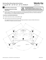
Assembly & Installation Instructions:
Rise Quiet 2-Leg Pin Workcenter
RISE-2PIN-XXXX-24-X, RISE-2PIN-XXXX-30-X
B Feet
Qty: 2 C Frameset
Qty: 1 D Side Supports
Qty: 2
A Legs
Qty: 2
Required & Sold Separately
Worksurface
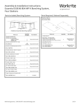
Verify that you have all the hardware and tools needed for the assembly
Check your cartons against the list above to verify that you have all the parts needed.
You will also need the following tools:
Drill/driver with #2 Phillips head bit
" and " Allen bit for drill/driver
or and " Allan Wrenches provided
If you do not have a Workrite pre-drilled worksurface, you will also need:
⅛" drill bit
Tape measure
N " Allen Wrench
Qty: 1
O " Allen Wrench
Qty: 1
Hardware Kit
J
Round Bumpers
Qty: 8
K
Square Bumpers
Qty: 2
F -18 × 1" Flat Head Socket
Cap Screws
Qty: 8
G -20 × " Flat Head
Phillips Screws
Qty: 4
H #8 ×¾" Pan Head Phillips
Wood Screws
Qty: 8
I #10 × 2¼" Flat Head
Phillips Wood Screws
Qty: 6
E -18 × " Button Head
Socket Cap Screws
Qty: 4
M Zip Ties
Qty: 2
L Round Plugs
Qty: 12
0.362"
#2 Drive
0.116"
82° 0.190"
2 1/4"
#10 Screw Size
✓

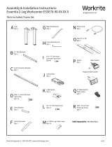
Layout Components in Assembly Area
Assemble near final installation location. Once the Workcenter is built it requires at least two people to li and
move into place. You'll need a large and clean area to assemble. Check your packaged contents against the parts
list on page 1 to verify that you have all the parts needed.
If you have a Workrite Pre-Drilled Worksurface, it may be easiest to assemble on the bottom of the worksurface,
using the pre-drilled holes as a guide.
Place Legs (A), Feet (B), Framesets (C) and Side Bars (D) on the floor or bottom of your worksurface.
Carefully unpack and arrange all hardware.
2 of 6 Workrite Ergonomics | 800.959.9675 www.workriteergo.com
1
C
A
A
D
B
B
D
Two Leg Pin
Frameset Hardware
E
F
G
H
I
J
K
L
M
N
O

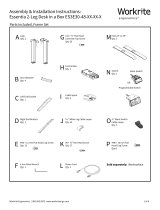
Attach Side Bars & Bumpers to Underside of Framesets
Attach Side Bars (D) to Frame Assembly with
¼-20 × ⅝" Flat Head Phillips Cap Screws (G).
Apply the six Round Bumpers (J) at mount
location on the Frameset as shown. Apply
the Square Bumper (K) at the Joining
Bracket location, just to the side of the
center hole.
Attach Framesets to Legs
Flip the Frameset over so the Bumpers and Side Bars
will rest on the Worksurface.
Slide Legs into frameset.
Attached the two legs to the
frameset using eight -18 × 1" Flat
Head Socket Cap Screws (F).
Workrite Ergonomics | 800.959.9675 www.workriteergo.com 3 of 6
To avoid stripping the threads, always
insert and make the first few turns of the
screw BY HAND, ensuring it is in straight.
a
b
2
G -20 × " Flat Head
Socket Cap Screw
Hardware at actual size
J
Round Bumpers
Hardware at actual size
K
Square Bumpers
Hardware at actual size
Make sure Frameset is oriented with
"knee saver" area towards user Side Bar (D)
facing down
F
F
A
A
3
a
a
F -18 × 1" Flat Head
Socket Cap Screw
Hardware at actual size
b
b
To avoid stripping the threads, always
insert and make the first few turns
of the screw BY HAND with provided
Allen wrench, ensuring it is in straight.
C
J
K
C
a
b
G
D
Joining Bracket

Expand Framesets to Correct Length
If you have a Workrite pre-drilled Worksurface:
Extend the frameset out towards the edge of the
worksurface.
Align frameset holes with pre-drilled holes in the
undersides of the worksurface.
Adjust Joining Brackets so center bracket hole aligns
with the center hole location.
Proceed to Step 6.
If you have a non- Workrite top:
Extend the frameset out towards the edge of the
worksurface
Align frameset parallel with the back of the
worksurface.
Position frameset 7.2" from rear of Worksurface and
extend frameset until the Side Bars (D) are about
1.5"–2" from the ends of the top.
Adjust Joining Brackets so center bracket hole is
centered between framesets.
Proceed to Step 7.
Attach Feet to Legs
Attach both Feet (B) To Legs (A) using four -18
× " Button Head Socket Cap Screws (E).
Note: Make sure the longer section of the foot
will face the front of the desk.
Tighten Securely.
4 of 6 Workrite Ergonomics | 800.959.9675 www.workriteergo.com
1.5"– 2"
7.2"
5
A
B
E
4
Make sure longer end of
foot is facing front of desk
Center Joining
Bracket hole aligns
with pre-drilled hole
Center Joining
Bracket hole
le to right
E -18 × " Button Head
Socket Cap Screw
Hardware at actual size
CAUTION! Be sure to use the correct
hardware for this step!
a
a
a
b
b
b
b
c
c
c
c
d
d

Attach Frameset to Workrite Pre-Drilled Worksurface
If you do not have a Workrite Pre-drilled Worksurface, skip to Step 7.
Position Frameset on the underside of the Worksurface
to align mounting holes in the Side Bars (D) and
Frameset (C) to pre-drilled holes in worksurface.
Attach the Side Bars (D) to the worksurface using four
#8× ¾" Pan Head Phillips Wood Screws(H).
Attach the Frameset assembly with three of the longer
#10× 2¼" Flat Head Phillips Wood Screws (I).
With frame securely fastened to the worksurface,
proceed to Step 8.
Attach Frameset to Non- Workrite Top
With Frameset positioned
correctly from Step 5, use a ⅛"
drill bit to drill pilot holes in
the seven frameset mounting
locations shown.
You may wish to mark your
drill bit so you do not drill any
more than ¾" deep to avoid
damaging your worksurface
top. Do not drill all the way
through worksurface!
Attach the Side Bars (D) to the worksurface using four
#8×¾"Pan Head Phillips Wood Screws(H).
Attach the Frameset assembly with three of the longer
#10× 2¼" Flat Head Phillips Wood Screws (I).
See Step 6 for hardware at actual size.
Workrite Ergonomics | 800.959.9675 www.workriteergo.com 5 of 6
>¾"
1
3
2
4
5
6
7
I
I
H
D
D
D
D
H
H
H
6
a
a
a
b
b
b
c
c
c
H
#8 × ¾ Phillips Pan Head
Wood Screw
Hardware at actual size
NOTE
Attaches Side Bars (D) to Worksurface.
I #10 × 2¼" Flat Head Phillips Wood Screws
NOTE
Attaches Frameset (C) to Worksurface.
Hardware at actual size
7
a
b
c
Mark drill bit so you do not
drill through your top
>¾"
1
2
a
Mark

Flip Workcenter Upright
Turn the workcenter over into an upright
position. Use at least two people to flip
over and position the workcenter.
Install Round Plugs in Frame
Install twelve Round Plugs (L) in frameset as shown.
Set Legs to Desired Height
Hold the attached Foot and Leg
assembly so it does not drop when
the Pin is loosened.
Loosen, but do not remove the Pin in
leg with " Allen Wrench (O) until
the leg moves freely.
Li or lower the Leg to desired
height. Use the height indicator for
reference.
Retighten pin in hole at new height.
Repeat for other leg at same height.
Cleaning Instructions
To clean the Essentia legs, apply cleaner to a so cloth.
Suggested cleaners: Windex or Formula 409.
Do not use solvents and do not saturate or spray cleaners directly onto workcenter base.
✓
Parts & Accessories
Visit http://workriteergo.com/documentation/other/workrite_ergonomics_pricing_specification_guide.pdf for
replacement parts.
✓
Adjust Leveling Guides
If necessary, adjust leveling guides on table feet to level the worksurface.
6 of 6 Workrite Ergonomics | 800.959.9675 www.workriteergo.com
#1500366 Rev B
10
8
11
9
aa
b
c
c
d
e
e
d
Pin
b
L
/