Page is loading ...

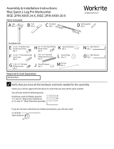
Assembly & Installation Instructions:
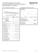
Rise Quiet 2-Leg Electric Workcenter
RISE-2E-3044-X, RISE-2E-4674-X, RISE-2E-7694-X
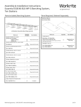
Required & Sold Separately
Worksurface
Two Leg Frameset, Components & Hardware
Hardware Kit 1
Silence Kit 1 Cable Mgt. Kit 1Collision Detection System (CDS) Kit
X
Round Bumpers
Qty: 8
X
Round Bumpers
Qty: 2
R
" P-Clips
Qty: 6
Q
" P-Clips
Qty: 2
R
" P-Clips
Qty: 6
S
#6 × ⅝" Phillips Flat
Head Wood Screw
Qty: 8
S
#6 × ⅝" Phillips Flat
Head Wood Screw
Qty: 6
O
#8 × ½" Self Tapping
Phillips Head Screws
Qty: 2
P
#8 × ¾" Phillips Pan
Head Wood Screw
Qty: 1
Y
Square Bumpers
Qty: 2
U -18 × 1" Flat Head Socket
Cap Screws
Qty: 8
V -20 × " Flat Head
Phillips Screws
Qty: 4
M #8 × 1" Phillips Pan Head
Wood Screws
Qty: 8
M
#8 × 1" Phillips Pan
Head Wood Screws
Qty: 6
W#10 × 2½" Phillips Pan
Head Wood Screws
Qty: 6
T -18 × " Button Head
Socket Cap Screws
Qty: 4
L
16 mm Steel Washers
Qty: 6
B Feet
Qty: 2 C Frameset
Qty: 1 E Switch
Qty: 1
D Side Bars
Qty: 2
I Leg Cable
Qty: 1
H Power Supply Bracket
Qty: 1 J Power Cable
Qty: 1
A Legs
Qty: 2
K 20 mm Foam Washers
Qty: 12 N Collision Detection
Sensor
Qty: 1
Z Zip Ties
Qty: 2
G Power Supply*
Qty: 1
F 3.5 mm × 16 mm Phillips
Head Wood Screw
Qty: 2
*A second Power Supply may be added
to this system as a separate purchase.
D Round Plugs
Qty: 24
D
Note: If you are assembling a 3-Leg Frameset, use instructions in the Third Leg Framset for complete assembly
instructions.
Workrite Ergonomics | 800.959.9675 www.workriteergo.com 1 of 12

WARNING: Maximum loading of frameset is 265 lb. (120 kg.). Maximum load includes the weight of the table top
itself, any equipment placed upon it, and any equipment suspended or hanging under it. Loading should be evenly distributed over table
surfaces.
Rise 2-Leg
V = 120 VAC, 60 Hz
3.2 A maximum with single power supply
Duty cycle: 1 minute on/ 9 minutes o.
IMPORTANT SAFETY INSTRUCTIONS:
When using an electrical furnishing, basic precautions should always be followed, including the following:
Read all instructions before using this Rise Quiet Frameset.
DANGER: To reduce the risk of electric shock, always unplug this Rise Quiet Frameset from the electrical outlet before cleaning.
CAUTION-RISK OF ELECTRIC SHOCK. This unit may have two power cords. Unplug both cords before moving or servicing this
furnishing.
WARNING: To reduce the risk of burns, fire, electric shock, or injury to persons:
1. Unplug from outlet (or outlets if equipped with a second power supply) before putting on or taking o parts, moving or servicing.
2. Close supervision is necessary when this furnishing is used by, or near children, invalids, or disabled persons.
3. Use this furnishing only for its intended use as described in these instructions. Do not use attachments not recommended by the
manufacturer.
4. Never operate this furnishing if it has a damaged cord or plug, if it is not working properly, if it has been dropped or damaged, or dropped into
water. Return the furnishing to a service center for examination and repair.
5. Keep all cords away from heated surfaces.
6. Do not use outdoors.
7. Do not operate where aerosol (spray) products are being used or where oxygen is being administered.
8. To disconnect, remove plug from outlet (or outlets if equipped with a second power supply).
9. Each Rise Quiet Frameset intended to support an equipment payload capacity of 265 lb. (120 kg.).
SERVICING OF DOUBLE-INSULATED PRODUCTS
In a double-insulated product, two systems of insulation are provided instead of grounding. No grounding means is provided on a double-
insulated product, nor is a means for grounding to be added to the product. Servicing a double-insulated product requires extreme care and
knowledge of the system, and is to be done by a qualified service personnel. Replacement parts for a double-insulated product must be identical
to the parts they replace. A double-insulated product is marked with the words “DOUBLE INSULATION” or “DOUBLE INSULATED”. The symbol
(square within a square) is also able to be marked on the product.
FOR COMMERCIAL USE ONLY
SAVE THESE INSTRUCTIONS
Verify that you have all the hardware and tools needed for the assembly
Check your cartons against the list above to verify that you have all the parts needed.
You will also need the following tools:
Drill/driver with #2 Phillips head bit
" Allen bit for drill/driver
or " Allan Wrench (Z) provided
If you do not have a Workrite pre-drilled worksurface, you will also need:
⅛" drill bit
Tape measure
2 of 12 Workrite Ergonomics | 800.959.9675 www.workriteergo.com
✓
An electric Drill/Driver is
recommended over hand
tools for this installation.

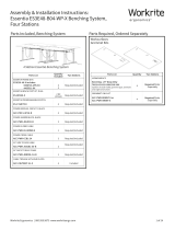
Layout Components in Assembly Area
Assemble near final installation location. Once the Workcenter is built it requires at least two people to li and
move into place. You'll need a large and clean area to assemble. Check your packaged contents against the parts
list on page 1 to verify that you have all the parts needed.
If you have a Workrite Pre-Drilled Worksurface, it may be easiest to assemble on the bottom of the worksurface,
using the pre-drilled holes as a guide.
Place Legs (A), Feet (B), Framesets (C) and Side Bars (D) on the floor or bottom of your worksurface.
Set the Switch (E), Collision Detection Sensor (N) packaged separately, and Power components (G,H,I & J) within
easy reach.
Carefully unpack and arrange all hardware.
Note! You will have many pieces in common and some VERY SIMILAR parts in the Silence Kit, Collision Detection
Kit,Cable Management and Hardware Kit. Use caution!
Workrite Ergonomics | 800.959.9675 www.workriteergo.com 3 of 12
1
C
A
A
D
B
B
D
I
J
H
G
Two Leg Frameset Hardware CDSSwitch
K
L
M
EN
O
P
R
S
F
R
Q
S
T
U
V
M
W
X
X
Y
Z
DD

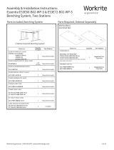
Attach Side Bars & Bumpers to Underside of Framesets
Attach Side Bars (D) to Frame Assembly with
¼-20 × ⅝" Flat Head Phillips Cap Screws (V).
Apply the six Round Bumpers (X) at mount
location on the Frameset as shown. Apply
the Square Bumper (Y) at the Joining Bracket
location just to the side of the center hole.
4 of 12 Workrite Ergonomics | 800.959.9675 www.workriteergo.com
XY
To avoid stripping the threads, always insert and make
the first few turns of the screw BY HAND with the provided
Allen wrench, ensuring it is in straight.
C
a
a
b
b
V
D
2
V -20 × " Flat Head
Socket Cap Screw
Hardware at actual size
X
Round Bumpers
Hardware at actual size
Y
Square Bumpers
Hardware at actual size
Joining Bracket

Attach Feet to Legs
Attach both Feet (B) To Legs (A) using four -18 × " Button
Head Socket Cap Screws (T). Make sure to use the correct
BUTTON HEAD Screws!
Note: Make sure the longer section of the foot will face the front
of the desk.
Tighten Securely.
Attach Framesets to Legs
Flip the Framset over so the Bumpers and Side Bars
will rest on the Worksurface.
Loosen the Joining Bracket on the Frameset at
locations shown with the Allen head bit or wrench.
NOTE! Loosen frameset but do not disassemble!
Move the internal Joining Brackets out of the way to
allow attachment of legs. Keep frameset loose.
With frameset Joining Bracket still
loose, attach the two legs to the
frameset using eight -18 × 1" Flat
Head Socket Cap Screws (U).
Workrite Ergonomics | 800.959.9675 www.workriteergo.com 5 of 12
Front of desk
A
B
T
4
Make sure longer end of
foot is facing front of desk
Make sure Framseset is oriented
with "knee saver" area towards user Side Bar (D)
facing down
U
U
A
A
3
a
a
a
U -18 × 1" Flat Head
Socket Cap Screw
Hardware at actual size
b
b
c
c
c
Joining Bracket
Joining Bracket
To avoid stripping the threads, always
insert and make the first few turns
of the screw BY HAND with provided
Allen wrench, ensuring it is in straight.
C
T -18 × " Button Head
Socket Cap Screw
Hardware at actual size
CAUTION! Be sure to use the correct
hardware for this step!

Expand Framesets to Correct Length
With Legs & Feet secure but the frameset Joining
Bracket still loose, extend the frameset out towards
the edge of the worksurface.
If you have a Workrite pre-drilled Worksurface:
Align frameset holes with pre-drilled holes in the
undersides of the worksurface.
Adjust Joining Brackets so center bracket hole aligns
with the center hole location.
Proceed to Step 6.
If you have a non- Workrite top:
Align frameset parallel with the back of the
worksurface.
Position frameset 7.2" from rear of Worksurface and
extend frameset until the Side Bars (D) are about
1.5"–2" from the ends of the top.
Adjust Joining Brackets so center bracket hole is
centered between framesets.
Proceed to Step 7.
6 of 12 Workrite Ergonomics | 800.959.9675 www.workriteergo.com
1.5"– 2"
7.2"
5
D
a
b
b
b
c
c
c
d
d
D
a
c
b
Adjust Joining Brackets
so middle hole aligns
with screw location.
Adjust Joining
Brackets so middle
hole is centered.
Note: Avoid trip or tip hazards!
For uniquely shaped, non-standard
worksurfaces, it is the installers
responsibility to position the
worksurface to minimize extended
overhangs and position feet fully
under the worksurface.

Attach Frameset to Workrite Pre-Drilled Worksurface
If you do not have a Workrite Pre-drilled Worksurface, skip to Step 7.
With Frameset positioned correctly from Step 5, carefully li Frameset (C) to place the Power Supply Bracket (H)
under the Frameset at location shown.
Carefully li the Frameset to place seven 20 mm Foam Washers (K) at all frame mount locations UNDER the
frameset as shown. Be sure to keep frameset aligned with pre-drilled holes.
Attach the Side Bars (D) to the worksurface using four of the 16 mm Steel Washers (L), four 20 mm Foam Washers
(K) and four #8 × ¾" Pan Head Phillips Wood Screws(M).
Attach the Frameset assembly with two 16 mm Steel Washers (L), three Foam Washers (K) and three of the
longer × 2⅛" Flat Head Phillips Wood Screws (W). NOTE: No 16 mm Steel Washers (L) and only one BOTTOM
Foam Washer (K) are used in the Joining Bracket center frame location.
With frame securely fastened to the worksurface, re-tighten the Joining Brackets loosened in Setp 3a.
Proceed to Step 8.
Workrite Ergonomics | 800.959.9675 www.workriteergo.com 7 of 12
6
a
b
c
d
e
L #8 × ¾ Phillips Pan Head
Wood Screw
Hardware at actual size
NOTE
Attaches Side Bars (D) to Worksurface.
K
K
a
c
d
M
D
L
V #10 × 2½" Phillips Pan Head Wood Screws
NOTE
Attaches Frameset (C) to Worksurface.
Hardware at actual size
Joining Bracket
location, bottom Foam
Washer (J) only.
K located between
frameset and worksurface
K located
between frameset
and worksurface
e
Retighten
b
H
C
K
c
e
W
C
C
K
Kc
e
W
L
K 20 mm Foam Washers
Hardware at actual size

Attach Frameset to Non- Workrite Top
With Frameset positioned correctly from Step 5, use a ⅛" drill bit to drill pilot holes in the seven frameset
mounting locations shown.
You may wish to mark your drill bit so you do not drill any more than ¾" deep to avoid damaging your
worksurface top. Do not drill all the way through worksurface!
With frame set positioned over pilot holes, li Frameset (C) to place the Power Supply Bracket (H) under the
Frameset at location shown.
With frame set positioned, li Frameset (C) to place twelve 20 mm Foam Washers (K) at all frame mount
locations UNDER the frameset. Be sure to keep frameset aligned with pilot holes.
Attach the Side Bars (D) to the worksurface using four of the 16 mm Steel Washers (L), four 20 mm Foam Washers
(K) and four #8 × 1" Pan Head Phillips Wood Screws(M).
Attach the Frameset (C) with two 16 mm Steel Washers (K), four Foam Washers (J) and three of the longer ×
2⅛" Flat Head Phillips Wood Screws (V). NOTE: No 16 mm Steel Washers (K) and only one BOTTOM Foam Washer
(J) are used in the Joining Bracket center frame location.
8 of 12 Workrite Ergonomics | 800.959.9675 www.workriteergo.com
>¾"
1
3
2
4
5
6
7
7
a
b
c
d
e
Mark drill bit so you do not
drill through your top
Joining Bracket
location, bottom Foam
Washer (K) only.
K located between
frameset and worksurface
K
K
c
d
M
D
L
K located between
frameset and worksurface
K
c
e
W
C
K
K
c
e
W
C
L
b
H
C
1.5"– 2"
7.2"
1
3
4
5
67
2
8
>¾"
a
Mark

Install Switch
Install your Switch (E) using two 3.5mm×16 mm
Pan Head Screws (F).
If you have a Workrite pre-drilled Worksurface:
Locate the pre-drilled holes near the front edge of
the Worksurface and attach.
If you have a non-Workrite top:
Align the switch with the front edge of the top, use a
⅛" drill bit to drill pilot holes using the Switch holes
as a guide and attach.
Do not drill all the way through worksurface!
Attach Collision Detection Sensor to Frameset and
Worksurface
Attach the two Round Bumpers (X) to the contact surface of the
Collision Detection Sensor (N).
Place the bumpers down, contacting the worksurface and position on Frameset (C) as shown. Attach Collision
Detection Sensor (N) to worksurface with one #8 × ¾" Phillips Head Wood Screw (P).
Attach the Collision Detection Sensor (N) to the Frameset (C) using the two #8×¾" Self Tapping Screws (O). You
will need to apply pressure with the screw in place to make the "bit" of the screw drill into the frame then catch
to attach and hold secure.
Note: For larger framesets, it may be necessary to mount the Collision Detection Sensor at an alternative
location on the frame, closer to the switch location.
Workrite Ergonomics | 800.959.9675 www.workriteergo.com 9 of 12
9
E
F
O
8
a
c
c
b
c
b
Use Self Tapping Screws
to drill into frame.
Alternative location
Alternative location
CDS mount location
O #8 × ½" Self Tapping
Phillips Head Screw
Hardware at actual size
P
#8 × ¾" Phillips Pan
Head Wood Screw
Hardware at actual size
N
C
N
N
P
X
a
Improper installation of the Collision
Detection System may result in false
collision incidents. Please follow
instructions closely.
C

Route and Connect Cables
Connect Switch (E) to closest Leg (A).
Connect Leg Cable (I) from one Leg (A) to the other Leg (A).
Connect Collision Detection Sensor (N) to Switch (E).
Connect Power Supply cable (G) to closest Leg (A).
Plug Power Cord (J) into the Power Supply (G).
10 of 12 Workrite Ergonomics | 800.959.9675 www.workriteergo.com
10
a
a
b
b
d
e
c
c
To Power
Plug in
To Leg (A)
E
N
A
A
A
I
G
G
e
J
J
J
d
G

Attach Cables to Worksurface With P-Clips
Attach the P-Clips (Q & R) with #6 ×
⅝" Phillips Head Wood Screws (S) at
convenient locations to keep cables
up and out of the way being sure to
rout the cables through the Clips prior
to attaching to the underside of the
worksurface.
Note: the larger " P-Clips
(Q) are used on the Leg Cables
(I) in locations 6 & 7 and the
smaller " P-Clips (R) are
used on all other cables.
Insert Round Plugs
Insert the Round Plugs
(DD) into corrosponding
Frameset holes as shown.
Workrite Ergonomics | 800.959.9675 www.workriteergo.com 11 of 12
1
2
3
4
6
7
5
11
12
I
Q
R
DD

Download the Rise Programmable Control User Guide
To get the full ergonomic benefit of this Workcenter, download the Rise Programmable User Guide. It contains
detailed information on set up and programming of your Rise Workcenter Programmable Control.
http://workriteergo.com/support/rise-control
Cleaning Instructions
To clean the legs, apply cleaner to a so cloth.
Suggested cleaners: Windex or Formula 409.
Do not use solvents and do not saturate or spray cleaners directly onto workcenter base.
Parts & Accessories
Visit http://workriteergo.com/documentation/other/workrite_ergonomics_pricing_specification_guide.pdf for
replacement parts.
Put Workcenter Upright and Plug In Power Cord
Turn the workcenter over into an upright position. Use at least two people to flip
over and position the workcenter.
Plug the Power Cord (J) into the power outlet.
Initialize Legs
Aer all components are connected, and the power cord has been plugged
in, the Legs need to be initialized.
Press and hold the UP and DOWN arrows on the Switch for at least 8 seconds.
Release both buttons and immediately press the DOWN arrow. The display will show three dashes and a home
icon in the lower le of the display as the worksurface moves to its lowest position.
Once the worksurface stops moving, release the button and the three dashes will be replaced with the height
reading. The Legs are initialized and the Workcenter is ready to use.
Adjust Leveling Guides
If necessary, adjust leveling guides on table feet to level the worksurface.
12 of 12 Workrite Ergonomics | 800.959.9675 www.workriteergo.com
#1500359 - Rev B
16
✓
✓
13
Flip Workcenter on
its SIDE or BACK so
you do not damage
the switch.
a
a
b
b
14
a
b
c
15
You must complete this
initialization step or your
workcenter will NOT
function properly!
J
/