Page is loading ...

Workrite Ergonomics | 800.959.9675 www.workriteergo.com 1 of 9
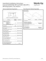
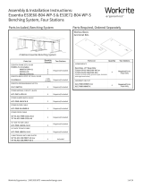
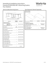
Assembly & Installation Instructions:
Sentinel Electric 30"–48" Base
ST2E-30-48-XXXXX-XX-X, ST3E-30-48-XXXXX-XX-X
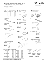
Parts Included
C DMP240 Power Supply
Qty: 1
D DMP240 Power Supply
Power Cord
Qty: 1
E Left Motor Bracket
Qty: 1
F Right Motor Bracket
Qty: 1
G Short Motor Bracket
Qty: 4
H Foot
Qty: 2
A Electric Leg Assembly
w/cable
Qty: 2
B Switch (Standard, Programmable,
or Bluetooth)
Qty: 1 I M6 × 1.0P × 12 mm
Flat Head Allen Screw
Qty: 12
K #8 × ⅝" Phillips Pan
Head Screw
Qty: 12
L #12 × ¾" Phillips Pan
Head Screw
Qty: 24
J M8 × 1.25P × 20 mm
Flat Head Allen Screw
Qty: 4
O 4 mm Allen Wrench
Qty: 1
P 5 mm Allen Wrench
Qty: 1
N P-Loop
Qty: 10
Q Glide
Qty: 4
M Cable Spool
Qty: 2
Tools Required:Worksurface Required, Sold Separately:
Worksurface Required, Sold Separately:
24" Deep: ST3423-B3-XXXXXXX, ST4023-B3-XXXXXXX, ST4623-B3-XXXXXXX ST343423T-B3-XXXXXXX
30" Deep: ST3429-B3-XXXXXXX, ST4029-B3-XXXXXXX, ST4629-B3-XXXXXXX, ST404023-B3-XXXXXXX,
ST464623-B3-XXXXXXX, ST464629-B3-XXXXXXX, ST404023T-B3-XXXXXXX, ST464623T-B3-XXXXXXX
ST343429T-B3-XXXXXXX, ST404029T-B3-XXXXXXX, ST464629T-B3-XXXXXXX
Cordless Drill #2 Phillips Bit
Screwdriver or
Driver/Drill
⅛" pilot drill bit
pencil
3⁄32" pilot drill bit
#3 Phillips Bit
Screwdriver or
Driver/Drill
Width Depth
24" Feet Rectangle 34–48" 23–24"
30" Feet
Rectangle 34–48" 29–30"
Equal Corner 40–48" × 40–48" 23–24"
46–48" × 46–48" 29–30"
120 Degree
34–36" × 34–36" 23–24" or 29–30"
40–42" × 40–42" 23–24" or 29–30"
46–48" × 46–48" 23–24" or 29–30"

2 of 9 Workrite Ergonomics | 800.959.9675 www.workriteergo.com
SAVE THESE INSTRUCTIONS
WARNING: Maximum equipment loading of table assembly in addition to specied top is as follows:
■ Maximum top weight:80 lb (36.4KG)
■ Maximum 2 Stage (ST2E-XX-XX-XX-X) Equipment Load: 125 lb (56.8 kg)
■ Maximum 3 Stage (ST3E-XX-XX-XX-X) Equipment Load 200 lb (90.9 kg)
Loading should be evenly distributed over table surfaces.
V = 120 VAC, 60 Hz / 4 A maximum
FLAMMABILITY: All worksurfaces used must meet UL 962 ammability requirements
■ Flame Spread Rating maximum 200
■ Smoke Developed Index maximum 450
WORKSURFACE MATERIAL: This frameset is designed to accommodate worksurfaces made from Industrial Particle Board with a minimum
thickness of 1".
Intended for indoor use only.
For commercial & residential use only
IMPORTANT SAFETY INSTRUCTIONS:
When using an electrical furnishing, basic precautions should always be followed, including the following:
Read all instructions before using this Sentinel Work Center.
DANGER: To reduce the risk of electric shock, always unplug this Sentinel Work Center from the electrical outlet before cleaning or servicing.
WARNING: To reduce the risk of burns, re, electric shock, or injury to persons:
1. Unplug from outlet before putting on or taking off parts.
2. Close supervision is necessary when this furnishing is used by, or near children, invalids, or disabled persons.
3. Use this Sentinel Work Center only for its intended use as described in these instructions, do not use attachments not
recommended by the manufacturer.
4. Never operate this Sentinel Work Center if it has a damaged cord or plug, is not working properly, has been dropped or
damaged, or dropped into water. Return the furnishing to a service center for examination and repair.
5. Keep the cord away from heated surfaces.
6. Do not operate outdoors.
7. Do not operate where aerosol (spray) products are being used or where oxygen is being administered.
8. To disconnect, remove plug from outlet.
9. Do not exceed maximum load recommendations.
Polarized Plug Instructions (Only applicable to products having a polarized plug power cord):
Some products include a polarized plug—see Figure A (One A/C plug blade wider than the other)—to reduce the risk of
electrical shock. A polarized plug only ts a polarized power outlet one way. If the polarized plug does not t properly into the
electrical outlet turn the power plug over to see if it then ts properly and fully into the outlet. If the plug does still does not t
the outlet, contact a certied electrician to install the correct matching polarized electrical outlet.
Caution: Never modify the power cord plug in any way
Double-Insulated Products Instructions:
Some products are double-insulated. No means of grounding is required or provided on a double-insulated product; nor is a
means for grounding to be added to the product. The plug in a double insulated system is shown in Figure A. Double-insulated
products are indicated with markings of “double-insulated” or the “double box symbol” or both.
Grounding Instructions (For grounded electric products only):
Products with grounded power cords are for use on a nominal 120 V circuit and has a grounded plug as shown in Figure B
Make sure the product is connected to an electrical outlet having the same conguration as the plug shown in Figure C.
Caution: Never modify, remove, or use adaptors that eliminate the ground connections from the grounded power cord
A/C Power:
Products sold in North America and other regions are 120 V A/C as marked on the power supply/control box of the furnishing
and are to be used on a normal 120 V A/C circuit. Always follow the instructions above for power connection using grounded or
double insulated power cords as supplied.
• Only use power cord(s) supplied with your electric product
• Never modify, alter, use an adaptor, or change the electrical system of this product in any way.
Warning: Doing so may cause risk of electrical shock or re
Illustration Disclaimer—Power Plug and Receptacle Images:
In some cases, the images in this instruction may not match the power cord supplied with your electrical furnishing based on your region.
Plug type, blade size, and shape may change.
Grounding Pin
Figure B
Grounded Outlet
Figure C
Polarized Plug
Figure A

Workrite Ergonomics | 800.959.9675 www.workriteergo.com 3 of 9
Attach short motor brackets (G) to the legs (A) with two (2)
#M6 × 1.0P × 12 mm at head Allen screws (I) and tighten
securely with the 4 mm Allen Wrench (O).
Attach left motor bracket (F) and right motor bracket (E) to
sides of the legs (A) using #M6 × 1.25P × 12 mm at head
Allen screws (I) and tighten securely with the 4 mm Allen
wrench (O).
Note: The right bracket will be on the left and left bracket
on the right when upside down
ATTACH BRACKETS TO LEGS
1.1
1.2
1
Hardware at actual size
I M6 × 1.0P × 12 mm Flat Head
Allen Screw
1.1
1.2
A
G
E
O
I
IG
I
F
A
I
G
I
I
G

4 of 9 Workrite Ergonomics | 800.959.9675 www.workriteergo.com
Position leg assembly 2.875" from the sides and 6.5"
from the back of the worksurface, making sure the legs
are parallel with the back edge of the worksurface.
Using the ⅛" drill bit, drill ¾" deep pilot holes in the four
corner locations.
ATTACH LEG ASSEMBLIES TO TOP
2.1 2.2
Note: We recommend you mark your drill bit at ¾" to
prevent drilling too deep.
Caution: Do not drill through the worksurface!
Install four (4) #12 × ¾" Phillips pan head screws (L) into the
4 corner locations and tighten securely.
Warning: Do not over-tighten and strip the screws into the top.
Using the ⅛" drill bit, drill ¾" deep pilot holes in the remaining
locations in brackets on the legs.
Install #12 × ¾" Phillips pan head screws (L) into all the pilot
holes and tighten securely.
2.3
2.4
2.5
2
Front
2.2
2.4
2.5
2.3
2.1
2.875" 6.5"
L
L
L
L
L #12 × ¾" Phillips Pan Head
Screws

Workrite Ergonomics | 800.959.9675 www.workriteergo.com 5 of 9
1.00
Place a foot (H) onto each leg as shown. Install two (2) M8 × 1.25P × 20 mm
at head Allen screws (J) into each foot and tighten securely with the 5 mm
Allen wrench (P).
Choose the switch location for either right or left hand installation.
Note: Right is on the left when table is upside down.
Place the switch (B) as shown and drill ½" deep pilot holes with
a 3⁄32" drill bit.
Install two (2) glides (Q) into each foot as shown.
Measure and mark the switch location with a pencil on the top
using the dimensions shown.
Install two (2) #8 × ⅝" Phillips screws (K) and tighten securely.
ATTACH FEET
ATTACH SWITCH
3.1
4.1
3.2
4.2
4.4
4.3
3
4
4.3
3.1
3.2
4.2
4.4
K #8 × ⅝" Pan Head
Screw
Q
Q
Q
Q
Hardware at actual size
J M8 × 1.25P × 20 mm Flat Head
Allen Screw
J
J
J
P
H
H
B
K

6 of 9 Workrite Ergonomics | 800.959.9675 www.workriteergo.com
Place the DMP240 power supply (C) in the center of the top
as shown and drill ¾" deep pilot holes with the ⅛" drill bit.
Place a cable spool (M) on each side of the power supply
between the leg and the power supply. Drill ¾" deep pilot
holes with the ⅛" drill bit for each cable spool.
Attach the power supply to the top using two (2) #12 × ¾"
Phillips pan head screws (L) and tighten securely.
Attach each cable spool (M) to the top using one (1)
#12 × ¾" Phillips pan head screws (L) and tighten securely.
ATTACH POWER SUPPLY & CABLE SPOOLS TO WORKSURFACE
5.1
5.3
5.2
5.4
5
L
L
L
5.2
5.4
M
M
C
L #12 × ¾" Phillips Pan Head
Screws

Workrite Ergonomics | 800.959.9675 www.workriteergo.com 7 of 9
Route the left leg cable around the left cable spool to take
up extra length and plug it into the power supply.
Carefully lift and turn table over into use position.
Route the switch cable around the nearest cable spool to
take up extra cable length and plug it into the power supply.
Route the right leg cable around the right cable spool to
take up extra length and plug it into the power supply.
Lift and carry to move the table into the location it is to be
used. Plug the table into a 120 V outlet. The Sentinel table
will take a few seconds to self-initialize. You will hear a few
beeps and the table will be ready to operate.
Plug the DMP240 power supply power cord (D) into the
power supply.
Place P-loops (P) on the switch and leg cables to secure
them under the top as shown and drill ½" deep pilot holes for
each P-loop with a 3⁄32" drill bit.
Install one (1) #8 × ⅝" Phillips pan head screw (K) into each
P-loop and tighten securely.
CONNECT LEG CABLES, SWITCH CABLE AND POWER CORD TO
POWER SUPPLY & SECURE CABLES TO TOP WITH P-LOOPS
TURN TABLE OVER & POWER UP
6.1
7.1
6.3
6.2
7.2
6.4
6.5
6.6
6
7
6.3
6.4
6.6
6.2
6.1
D
K
K #8 × ⅝" Phillips Pan
Head Screw
7.1
7.2
N
N
N

8 of 9 Workrite Ergonomics | 800.959.9675 www.workriteergo.com
TROUBLE SHOOTING
Note: If the table does not operate properly upon power-up, a cable connection may not be connected correctly. Two things must be done to
correct this problem.
Step 1.) First check all cable connections to the power supply. If cables are properly connected they will be locked in place. If you pull back
on each cable and one comes unplugged, re-insert the cable and push in rmly until it locks. Test by pulling back to be sure the cable is
properly connected.
Step 2.) Perform the “Restore Factory Settings” procedure. Follow the “Restore Factory Settings” instructions and reset the system.
Note: It’s important to follow the steps precisely as noted or the “Restore Factory Settings” may not restore properly allowing both of the legs of the
table to operate properly once the connection issue is corrected. Repeat the “Restore Factory Settings” procedure again if necessary
Once you’ve corrected the connection problem and performed the reset the table should operate as normal. Repeat starting with Trouble Shooting
Step 1 if the table still does not operate properly.
If you still have problems with your table, please contact Workrite Ergonomics at (800) 959-9674 “Press 2 for Technical Support” or contact us at
With this function, you can reset the Sentinel series switches to their original factory settings.
Caution: Restoring "Factory Settings" will remove height limits. Perform this step only if needed to restore the table
Height Control
Up Down
LED indicator light
FACTORY RESET
SENTINEL "SS" STANDARD SWITCH
Step User input
1. Disconnect the Table System from 120 V power by removing the power cord plug from the power supply
Note: If your Sentinel Base has more than one power supply, all power cords must be removed in t his step
2. Press and hold the UP UP and DOWN buttons
3. While holding the UP and DOWN buttons, reconnect the 120 V power cord to the power supply
Note: If your Sentinel Base has more than one power supply, all power cords must be reconnected in t his step
4. UP and DOWN buttons
5. Press the DOWN button until the table moves and stops. The "Restore Factory Settings" step is now completed
.

9 of 9 Workrite Ergonomics | 800.959.9675 www.workriteergo.com
1500469 Rev E
Cleaning Instructions
To clean the Sentinel legs, apply cleaner to a soft cloth.
Suggested cleaners: Windex or Formula 409.
Do not use solvents and do not saturate or spray cleaners directly onto work center base.
Parts & Accessories
Visit for
replacement parts.
SENTINEL "BT" BLUETOOTH SMART APP SWITCH
Step User input
1. Disconnect the Table System from 120 V power by removing the power cord plug from the power supply
Note: If your Sentinel Base has more than one power supply, all power cords must be removed in this step
2. Press and hold the UP and DOWN buttons
3. While holding the UP and DOWN buttons, reconnect the 120 V power cord to the power supply
Note: If your Sentinel Base has more than one power supply, all power cords must be reconnected in this step
4. UP and DOWN buttons
5. Press the DOWN button until the table moves and stops. The "Restore Factory Settings" step is now complete
Down
Button
Up
Button
LED indicator light
• Green: Available
• Red: Occupied
SENTINEL "PS" PROGRAMMABLE SWITCH
Step User input
1. Press the "1" "2" and UP button simultaneously for 10 seconds until "S–" appears
2. Press the UP button two times until "S–0" appears
3. Press the "Save" button
4. Press the DOWN button until the table moves and stops. The "Restore Factory Settings" step is now complete
Up
Down
Memory 1 Button
Memory 2 Button
Digital Readout
Save
Button
User
Button
29.00
FACTORY RESET
SENTINEL "PB" PROGRAMMABLE SWITCH
/