Page is loading ...

Installation Manual – February 2023
Enclose ®
Part Number: 127-8829
Revision: 3.1


Rev: 3.1
CUSTOMER SERVICE PHONE: 1-800-426-8562
Thank you for choosing ENCLOSE by Haworth.
Enclose is a non-progressive, unitized wall panel system. The order of installation should be carefully
considered before the installation phase of the project begins. Before determining where to start and
how to progress, it is important to clearly understand the customer expected layout regarding wall panel,
door, intersection and attachment locations.
This guide covers the installation methods for many of the doors, wall panels, attachment conditions
as well as combinations of these elements, however due to the versatility of the Enclose product, some
applications may not be shown. In order to understand each panel, component, connection and
application, please be sure to read all steps in their entirety and review the layout before starting the
installation. Site conditions (oor, ceiling and base building wall) as well as hardware specications may
necessitate an alternate installation method or starting point (datum) due to variances in critical areas.
Please contact your Regional Technical Representative or Sales Engineering if additional support is
required.
i

Rev: 3.1
CUSTOMER SERVICE PHONE: 1-800-426-8562
Table of Contents
1. Safety
- Working with Glass
- Cutting Aluminum/Plastic
2. General Installatoin Guidelines
- Tools Required
- Measuring
- Floor Types
- Ceiling Types (Including Grid Clips)
3. Starters & Posts
4. Floor to Ceiling
- Ceiling Track
- Panel connections
5. Freestanding & Chinook Beams
6. Stack-on Modules
7. Electrical Application - Powerbase
8. Cuttable and Other Panel Types
-Side Cuttable
-Top Cuttable
-Interface Panels
-Frameless Corners
9. Additional Walls Applications
-Spanning Tiles
-Plywood Backer
-Paintable Tiles
10. Wood/Metal Butt hinge Doors
11. Glass Slab Butt Hinge Doors - c/w Colcom Hinge
12. Glass Slab Pivot Door
13. Double Glazed Pivot Door
ii

Rev: 3.1
CUSTOMER SERVICE PHONE: 1-800-426-8562
Table of Contents Continued
14. Wood/Metal Sliding Door c/w Standard Track
15. Glass Slab Sliding Door c/w Standard Track
16. Wood & Metal Sliding Doors c/w Soft Close
17. Glass Slab Sliding Doors c/w Soft Close
18. Double Glazed Sliding Doors c/w Soft Close
19. Haworth Door Hardware
-D and Bar Pulls
-Lockset Patch housing and Covers
20. Proles - Quick Reference for Enclose Proles
iii

1.1
Rev: 3.1
CUSTOMER SERVICE PHONE: 1-800-426-8562
Working with Glass
Section 1 - Safety
When handling tempered glass use cut resistant gloves and safety glasses to protect yourself. When
staging or placing glass into frames also wear glass sleeves to protect your forearms from sharp edges.
all carts and staging surfaces must be padded.
When placing a pane into a frame, care must be taken not to load the weight of the panel on a single
Observe the glass stamp placement and keep placement consistent to outside bottom right when the
pane is placed within the frame.
Verify that the saw is cutting square and true by using a small square against the table and saw blade.
Make any corrections to the saw as needed.
before proceeding with the cut. Use masking tape and a small square on the part when marking the
desired length.
When cutting any plastic or metal, a full face shield and a long sleeves shirt should be used to protect
eyes, face and forearms from shavings.
Before marking the desired length on the part, slightly trim the factory edge to ensure squareness.
complete, remove any shavings within the channels of the extrusion with a brush or by tapping the part
over a dropsheet or garbage bin.
When cutting plastic clips that will fasten covers and caps to rails, back-cut the plastic clip slightly (1/2”)
to ease installation of the cap/covers.
Cutting Aluminum / Plastic
ENC®

2.2
Rev: 3.1
CUSTOMER SERVICE PHONE: 1-800-426-8562
Section 2 - Safety
ENC®
#2
Tools Required
Cordless drill with #2 square recess driver bits
Hammer drill (for concrete anchors or screws)
Vacuum
16 to 27 oz Deadblow Hammer
Tap block
Level (4’ and 2”)
Laser - 5 -point
Square (small)
Anvil Cutters
Tape Measure (Metric and Imperial)
1/8” Hex T Handle (Regular and Ball End)
Masking Tape
Pencil
Utility Knife
Screw Driver - Flat
Rubber Mallet
Personal Protection Equipment
1/8”
Robertson
Square Bit
360-Degree Laser
Level
#2

2.3
Rev: 3.1
CUSTOMER SERVICE PHONE: 1-800-426-8562
Before measuring the material to be cut ensure that the product that will receive the cut part is square
and tight to all corresponding material. When Cutting Rails or covers/caps all measurements should be
made to the milimeter or a 1/16” All joints should be tight and square to eachother. Caps and covers
should also be tight to corresponding material with no gaps.
Measuring
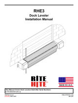
Floor Types
Ceiling Types
Due to the variety of ceiling construc-
tions and grid types, multiple fastening
solutions are available for ceiling
attachment.
The fastening solutions will determine
the “ceiling height” point of reference
since the top position of top horizontal
or top of framed panel may change
depending on the solution.
when taking site measurements during
the layout of installation process,
ceiling type and fastening soluion
should be taken into account.
The ceiling height measurement is
dened from the top of the nished
oor to the lowest surface of the ceiling
(this can be the tile, the grid or the
gypsum - see chart for r eference).
Concealed T-Bar Drywall (Gypsum)
O P
” Slotted ” Screw-Slot ” Dimensional T-Bar
” Reveal with
Flush Tegular Tile ¼ ” Reveal with
Flush Tegular Tile Flush Tegular Tile ” Tee with
Flush Tegular Tile ” Tee with
Flush Tegular Tile
M M M C C
Reveal ¼” Reveal Reveal Tee Tee
Ceiling Types and Attachment Ha rdware Kits
” T-Bar
Lay-In Tile Flush Tegular Tile ¼ ” Tegular Tile ” Tegular Tile ½ ” Tegular Tile
A A C E E
Ceiling
Tile
T-Bar
¼”
½”
Ceiling Grids and Tiles
1” T-Bar
Lay-In Tile Flush Tegular Tile ¼ ” Tegular Tile ” Tegular Tile ½ ” Tegular Tile
1” 1” 1” 1” 1”
¼” ½”
G G I K K
A - Clp 9/16“ TBar FlshTeg | LayInTile, 114-2182
C - Clp 9/16” TBar 1/4”TegTile | DimTbar, 114-2183
E - Clp 9/16” TBar 3/8” TegTile, 114-2184
G - Clp 1” TBar FlshTeg | 114-2185
I - Clp 1” TBar 1/4” TegTile, 114-2186
K - 1”Tbar 3/8” TegTile, 114-2187
M - Clp 9/16” Slotted | ScrewSlotGrd, 114-2187
O - Screw Concealed TBar, 114-2188
P - Screw Drywall, 114-2189
ENC is capable of, and intended, to be installed on all oor types and substrates.
Due to various oor constructions, the anchoring components are not provided by Haworth. The appro-
priate fastening components and frequency of attachment should be determined by the site engineer.

3.1
Rev: 3.1
CUSTOMER SERVICE PHONE: 1-800-426-8562
Adjustable Starter Low Prole Starter
Compressible Starter
Shown with optional
114-2202 Enc Compressible Starter Bracket
Section 3 - Starters, Intersections, End of Run
ENC®
Starter Types Cat# 122-4740
Cat# 122-4739

3.2
Rev: 3.1
CUSTOMER SERVICE PHONE: 1-800-426-8562
Starter Installation
Reveal Connector
(P3)
Compressible Starter
(P4)
X
X
COMPRESSIBLE STARTER
FOR DOORS/WALLS
NOTES: Seismic Applications
Starters must be anchored
to the hardwall in seismic
X = 31.8mm ±5mm
(1 1/4" ±3/16")
X = 12mm ±5mm
(1/2" ±3/16")
X = 61mm ±12mm
(2-13/32" ±1/2")
ADJUSTABLE OR
LOW PROFILE OR
1
2
P4
P2
P3
P3

3.3
Rev: 3.1
CUSTOMER SERVICE PHONE: 1-800-426-8562
114-2178
Reveal Connector
122-4732
Post 2 Way 90° Open
122-4732
Post 2 Way 90° Closed
Inner Corner Clip
Inner Corner Post Clip 135°
122-4733
Post 135
Post Inline 4 Inches
Post Inline 6 Inches
122-4734
Without Cutout
122-4731
Post Variable Angle
122-4739
Compressible Starter
OR
Post Inline 4 Inches
Post Inline 6 Inches
122-4735
With Cutout
OR
122-4730 122-4730 122-4730
114-2202
Compressible
Starter Bracket
Inner Corner Clip
Inner Corner Post Clip 90°
N
N1
O O1
P2
P3
P4
Q
Q1
Q2
Q3
N2
P
P
P1
P5
Post Types

3.4
Rev: 3.1
CUSTOMER SERVICE PHONE: 1-800-426-8562
2-Way (90°) 2-Way (135°)
Corner Reveal Connector Installation Cat# 114-2178
G
H
B
G
B
G
B
H
J
J
H
2-Way (90°) 2-Way (135°)2-Way
Connection
Reveal
Connection
BG
JH
3-Way 4-Way
G
H
G
H
G
H
G
H
G
G
B
B
B

3.5
Rev: 3.1
CUSTOMER SERVICE PHONE: 1-800-426-8562
Install 2-way & 3-way corner trim
1
2
2
2-Way 3-Way
3
Slide light block (P) down
2-Way 3-Way
Trim Installation
1
2
2
1
3
G
BB
G
G
B
B
A
A
P
P

3.6
Rev: 3.1
CUSTOMER SERVICE PHONE: 1-800-426-8562
1
2
R
P
B
End Of Run Installation Cat # 122-4730

4.1
Rev: 3.1
CUSTOMER SERVICE PHONE: 1-800-426-8562
#10-24 x 1/2" Screw
Self Drilling
(E)
1/4 - 20 Hex Nut
(C)
A
B
A
B
D
CONNECTOR
PLATE
E
1
B
A
CEILING
TRACK
CEILING TRACK
FLAP
C
L
CEILING
BRACKET
M
FOAM TAPE
A
L2
SPACER
Install ceiling track ap (B)
Ceiling Track Cat# 114-2179
Ceiling Track Flap Cat# 114-2180
Section 4 - Floor To Ceiling Panels
ENC®

4.2
Rev: 3.1
CUSTOMER SERVICE PHONE: 1-800-426-8562
Locate points onto ceiling for ceiling track (A)
(LAYOUT PLAN)
B
M
L
L
1/4 - 20 Hex Nut
(C)
2
3
A
M
L
L2
C
L2

4.3
Rev: 3.1
CUSTOMER SERVICE PHONE: 1-800-426-8562
Inline Condition
Splice Plates Cat # 114-2194
2-Way Condition
3-Way Condition

4.4
Rev: 3.1
CUSTOMER SERVICE PHONE: 1-800-426-8562
16"
Smooth Floor Attachment
Smooth Shoe Cat# 114-2193
3
Optional - Carpet Gripper CAT # 114-2191
16"
2
1
AB
AD
AB
NOTE: All product over
10-1/2’ feet will have to use
the respective “shot”
shoe/gripper solution for
oor lateral bracing.
Fastener (AD) specied by
others.
NOTE: All product over
10-1/2’ feet will have to
use the respective “shot”
shoe/gripper solution for
oor lateral bracing.
Fastener (AD) specied
by others.
NOTE: Only two smooth
grippers (AB) per panel.
NOTE: Every 16” is for
seismic conditions
"X"
AD
1
2
AC

4.5
Rev: 3.1
CUSTOMER SERVICE PHONE: 1-800-426-8562
GLASS PANELS
Cat# 114-3833
SOLID PANELS
Cat# 122-4741
A
Panel
B
Reveal Connector
CAT # 114-2178
E
Raceway Cover
D
Leveler Cover
F
Y-Bolt
Bracking Y-Bolt
CAT # 114-2190
Floor to Ceiling Panels

4.6
Rev: 3.1
CUSTOMER SERVICE PHONE: 1-800-426-8562
NOTE: Before installing panels install all
corner reveal connectors (H & J) to all
panels (A) used in corner conditions.
1Install corner reveal connector (H & J)
2-Way (90°) 2-Way (135°)
JH
A
2Modify reveal connector (H & J) for component (K) installation
AA
H J
K
NOTE: Install half reveal
connector (W) as shown.
W
/