Page is loading ...

RHE3
Dock Leveler
Installation Manual
This Manual Covers Dock Levelers Built After Serial Numbers:
07FE160001M and up
PRINTED IN U.S.A.
RITE-HITE PRINT SHOP
PUBLICATION NO. 1222
MAY 2007
MADE IN U.S.A.

2Pub. No. 1222 - May 2007
RITE-HITE®RHE3 Dock Leveler Installation Manual
NOTES

Pub. No. 1222 - May 2007 3
RITE-HITE®RHE3 Dock Leveler Installation Manual
TABLE OF CONTENTS
NOTICE TO USER . . . . . . . . . . . . . . . . . . . . . . . . . . . . . . . . . . . . . . . . . . . . . . . . . . . . . . . . . . . . . . . . . . . . . . . . . .3
SAFETY WARNINGS . . . . . . . . . . . . . . . . . . . . . . . . . . . . . . . . . . . . . . . . . . . . . . . . . . . . . . . . . . . . . . . . . . . . . . . .4
INSTALLATION INSTRUCTIONS . . . . . . . . . . . . . . . . . . . . . . . . . . . . . . . . . . . . . . . . . . . . . . . . . . . . . . . . . . . . . . .7
OPTIONAL TRANSITION PLATE INSTALLATION INSTRUCTIONS . . . . . . . . . . . . . . . . . . . . . . . . . . . . . . . . . . . .9
OPTIONAL HYDRAULIC POWER KIT INSTALLATION INSTRUCTIONS . . . . . . . . . . . . . . . . . . . . . . . . . . . . . .10
OPTIONAL TELESCOPING HANDLE INSTALLATION INSTRUCTIONS . . . . . . . . . . . . . . . . . . . . . . . . . . . . . . .14
WARRANTY . . . . . . . . . . . . . . . . . . . . . . . . . . . . . . . . . . . . . . . . . . . . . . . . . . . . . . . . . . . . . . . . . . . .BACK COVER
NOTICE TO USER
Your local RITE-HITE®representative provides a Planned Maintenance Program (P.M.P.) which can be fitted to your
specific operation. Call your local representative or the RITE-HITE®Corporation at 414-355-2600.
The RITE-HITE®products in this manual are covered by one or more of the following U.S. patents: 4,744,121;
4,819,770; 4,843,373; 4,865,507; 4,920,598; 4,995,130; 5,040,258; 5,111,546; 5,212,846; 5,271,183; 5,299,386;
5,311,628; 5,323,503; 5,375,965; 5,440,772; 5,442,825; 5,453,735; 5,531,557; 5,546,623; 5,553,987; 5,582,498;
5,664,930; 5,702,223; 5,762,459 (RE: 37,570); 5,882,167; 5,964,572; 6,010,297; 6,052,268; 6,065,172; 6,070,283;
6,074,157; 6,085,375; 6,092,970; 6,106,212; 6,116,839; 6,190,109; 6,220,809; 6,627,016; 6,238,163; 6,311,352;
6,322,310; 6,360,394; 6,368,043; 6,431,819; 6,488,464; 6,497,076; 6,499,169; 6,505,713; 6,524,053; 6,634,049;
6,654,976; 6,676,360; 6,726,432; 6,773,221; 6,832,403; 6,880,301 and pending U.S and foreign patent applications.
RITE-HITE®, LEVEL-RITE®, THINMANTM, SAFE-T-LIP®, HYDRACHEK®, WHEEL-LOKTM, DOK-LOK®, DUAL-DOK®,
SAFE-T-STRUTTM, DOK-COMMANDER®, JUMBOTM, HYDRA-RITETM and SAFE-T-GATE®are trademarks of RITE-HITE®
Corporation.

4Pub. No. 1222 - May 2007
RITE-HITE®RHE3 Dock Leveler Installation Manual
SAFETY WARNINGS
LOCKOUT/TAGOUT PROCEDURES
The Occupational Safety and Health Administration (OSHA) requires, in addition to posting safety warnings and barri-
cading the work area (including, but not limited to, trucking office and loading docks), that the power supply has been
locked in the OFF position or disconnected. It is mandatory that an approved lockout device is utilized. An example of
a lockout device is illustrated. The proper lockout procedure requires that the person responsible for the repairs is the
only person who has the ability to remove the lockout device.
In addition to the lockout device, it is also a requirement to tag the power control in a manner that will clearly note that
repairs are under way and state who is responsible for the lockout condition. Tagout devices have to be constructed
and printed so that exposure to weather conditions, or wet and damp locations, will not cause the tag to deteriorate or
become unreadable.
RITE-HITE®does not recommend any particular lockout device, but recommends the utilization of an OSHA approved
device (refer to OSHA regulation 1910.147). RITE-HITE®also recommends the review and implementation of an entire
safety program for the Control of Hazardous Energy (Lockout/Tagout). These regulations are available through OSHA
publication 3120.
When working with electrical or electronic con-
trols, make sure that the power source has been
locked out and tagged out according to OSHA
regulations and approved local electrical codes.
XXXXXXXXXXXX
XXXXXXXXXXX
OPERATE
DO NOT
LOCKOUT/TAGOUT
This is a statement of serious hazard. Failure to
follow the listed instructions could place the
individual at risk of serious injury or death.
This is the highest level statement. Failure to
follow the listed instructions will most likely
result in severe injury or death.
The statements used with this level of warning
deal with a safe operating procedure. If the pro-
cedure is ignored the possibility of personal
injury may exist.
IMPORTANT is used to draw attention to a pro-
cedure that needs to be followed to prevent
machine damage.

Pub. No. 1222 - May 2007 5
RITE-HITE®RHE3 Dock Leveler Installation Manual
OTHER IMPORTANT OPERATIONAL SAFETY WARNINGS
Never be under the dock leveler platform or lip
without:
• Installing the maintenance strut.
• If lip needs to be extended, follow
procedures shown under Safety Devices on
the following page.
• Turning off power to the control box.
• Locking out and tagging out the main
power source, as shown under Safety
Warnings on preceding page.
Always barricade the dock leveler at ground
level and dock level from any form of traffic
when maintenance is required.
Inspect the dock leveler monthly to ensure that
there are no broken or worn parts which could
cause injury to personnel or damage to the
equipment.
• Before starting installation or maintenance,
check and follow the safety procedures of
the facility where the dock leveler is being
installed.
• Never enter a truck/trailer until its brakes are
set, air has been dumped from air ride
suspension (if applicable), and you have
visually inspected to be sure truck/trailer is
securely held in place by a vehicle restraint
or wheel chock per OSHA regulations.
• Never operate the leveler with you, anyone,
or anything on, or in front of the leveler, or
without a truck/trailer parked in position, or
from on the truck/trailer bed.
• DO NOT operate with anyone under platform
or in front of the lip.
• When leveler is not in use, always store it.
• If a malfunction does occur, always call your
authorized RITE-HITE®service representative
immediately.

6Pub. No. 1222 - May 2007
RITE-HITE®RHE3 Dock Leveler Installation Manual
SAFETY DEVICES
Never be under the dock leveler platform or lip
without:
• Installing the Maintenance Strut. See right.
• Lockout/Tagout power supply.
- Turn off the power to the control box.
- Lockout/tagout the main power source, as
shown under Safety Warnings on the
inside front cover of this manual.
- Always barricade the leveler at dock level
and drive level to prevent any
unauthorized use of the leveler.
• If you are unable to install the Maintenance
Support properly, contact your authorized
RITE-HITE® Service Representative or RITE-
HITE® Customer Service at 1-414-355-2600.
• Post warnings and barricades at dock level
and at drive level to indicate that work is
being done around and under the leveler
platform.
• Lockout/Tagout power to the leveler and post
warnings when work is being performed on
the leveler.
The operation handle also serves as a
maintenance strut preventing the leveler from
rotating onto the maintenance personnel.
To install the strut:
• Rotate the leveler to its rearward position.
• Remove the clevis pin attaching the lip
latch to the underside of the lip.
When lifting lip (approx. 110 lbs.) use lifting
device (crane). Lifting by hand may cause
back injury.
• Rotate the lip up and over. Place the
handle in the socket provided.

Pub. No. 1222 - May 2007 7
RITE-HITE®RHE3 Dock Leveler Installation Manual
INSTALLATION INSTRUCTIONS
PREPARATION PRIOR TO INSTALLATION
1. Check pit to insure it meets pit details. If pit does not
match pit details, contact your local representative or
RITE-HITE®before proceeding.
NOTE:
Unit may not operate properly if pit is not correct.
2. The dock must be clean, straight, and free of
protrusions. Adequately sized dock edge steel must
be an integral part of the dock or a transition plate
with face plate must be utilized.
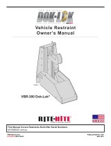
INSTALLATION PROCEDURES
1. Center the leveler in place. The top of faceplate
should be 5/16” ± 1/16” below the top surface of
dock edge steel (or transition plate if used).
2. Weld the leveler and bumper blocks to dock edge
steel and/or transition plate. Use 7018 welding rod.
3. All anchor holes must be anchored with 5/8” x 5L
concrete anchor bolts (RH# 65639) or plug welded
to dock edge steel. See figure 1.
4. Clean and paint all welded joints.
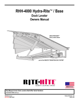
5. Lubricate dock leveler per lubrication chart. See
figure 2.
Handle
Storage
Socket
Operating
Socket
Transition plate must be installed on docks without proper dock-edge steel
Top of Faceplate 5/16” ± 1/16” below top of dock or Transition Plate
Bumper Flange
with Anchor Holes
5/16” ±1/16”
No gap between Faceplate
and Bumper Flange
108”
10”
MAX 1 3/4”
Anchor Leg
1/4” x 1-1/2” x 11” steel flat
with 90° bend to form 1-3/4” angle
CHANNEL: C8” x 11.5lb/ft
RECOMMENDED DOCK EDGE STEEL
(Not Supplied By Rite-Hite)
FIGURE 1 - INSTALLATION
• Post warnings and barricades at dock level
and at drive level to indicate that work is
being done around and under the leveler
platform.
• Lockout/Tagout power to the leveler and post
warnings when work is being performed on
the leveler.
See Step #3
1/4” Continuous Bumpers
FLATNESS: ± 1/8”
1/4” 3” Each End 1/4”
Above each hinge tube
welded to the faceplate

8Pub. No. 1222 - May 2007
RITE-HITE®RHE3 Dock Leveler Installation Manual
LUBRICATION CHART
FIGURE 2 - LEVELER LUBRICATION DETAIL
Lip
Lip Hinge
Deck
Spring Assembly
Lip Latch
Riser
Faceplate (Grease)
(Grease)
(Grease or Oil)
(Grease or Oil)
(Grease or Oil)
Maintenance Strut
Hinge Pin
Handle
Socket
Lip Stop
Hinge Pin
(Grease)

Pub. No. 1222 - May 2007 9
RITE-HITE®RHE3 Dock Leveler Installation Manual
OPTIONAL TRANSITION PLATE INSTALLATION
INSTRUCTIONS
108”
6ea. Anchor Holes
1) Install 5/8” x 5L Concrete Anchor Bolts (RH # 65639)
2) Grind Head Flush With Transition Plate
3) Weld To Transition Plate 1-1/2”
12”, 18”, or 24”
15-7/8”
66”, 72”, 78” or 84”
15-7/8”
Transition Plate must be installed on docks without proper Dock Edge Steel.
(8” Channel with anchor legs on 10” centers)
Set Faceplate of leveler 5/16” ± 1/16” below top surface of Dock Edge Steel
or Transition Plate
Bumper
Flange
No gap between Faceplate
and Bumper Flange
Anchor Holes
Deck
Lip
Faceplate
Dock
Edge
Steel
A
Detail A
21-1/2” for 24” Trans. Plate
15-1/2” for 18” Trans. Plate
9-1/2” for 12” Trans. Plate 2-1/2”
1/2” Chamfer
Transition Plate
3/16”
FIGURE 3 - TRANSITION PLATE INSTALLATION
1/4” Continuous Bumpers
1/4”
1/4” 3”
Each
End
Above each Hinge
Tube welded to the
Faceplate

10 Pub. No. 1222 - May 2007
RITE-HITE®RHE3 Dock Leveler Installation Manual
PREPARATION PRIOR TO INSTALLATION
1. Verify all components are in the shipping container, If
not contact your local representative.
2. Install maintenance strut.
OPTIONAL HYDRAULIC POWER KIT
INSTALLATION INSTRUCTIONS
• The Edge of Dock Leveler must be properly
installed prior to installation of the hydraulic
power kit in accordance with leveler
installation instructions.
• Post warnings and barricades at dock level
and at drive level to indicate that work is
being done around and under the leveler
platform.
• Lockout/Tagout power to the leveler and post
warnings when work is being performed on
the leveler.
PARTS LIST
ITEM PICTORIAL DESCRIPTION QTY
A 3/4” x 5” Clevis Pin 1
B 3/4” x 2-3/4” Clevis Pin 2
C Cylinder Bracket 1
D 3/4” Plain Washer 3
E Rue Ring Cotter 4
F 3/8” Bolt 2
G Hydraulic Power Unit 1
H Hydraulic Cylinder 1
I Electrical Control Box 1
J Reservoir Breather Cap 1
K Motor Mount Bracket 1
L Lift Arm, Hydraulic 1
The operation handle also serves as a
maintenance strut preventing the leveler from
rotating onto the maintenance personnel.
To install the strut:
• Rotate the leveler to its rearward position.
• Remove the clevis pin attaching the lip
latch to the underside of the lip.
When lifting lip (approx. 110 lbs.) use lifting
device (crane). Lifting by hand may cause
back injury.
• Rotate the lip up and over. Place the
handle in the socket provided.

Pub. No. 1222 - May 2007 11
RITE-HITE®RHE3 Dock Leveler Installation Manual
INSTALLATION PROCEDURES
1. Remove the existing lift arm from RHE. Be sure to
retain the clevis pins and washers.
2. Position the Lift Arm (L) and Cylinder Bracket (C) as
shown in figure 4. Reuse the clevis pins and washers
with new Rue Rings (E) to pin the Cylinder Bracket
(C) and Lift Arm (L) to the leveler.
3. Weld or anchor bolt the cylinder bracket flange to the
dock face with 5/8” x 5L concrete anchor bolts.
(RH# 65639)
4. Use one 2-3/4” long Clevis Pin (B), one 3/4” Washer
(D), and one Rue Ring Cotter (E) to pin the Motor
Mount Bracket (K) to the leveler as shown in figure 4.
5. Use one 2-3/4” long Clevis Pin (B), one 3/4” Washer
(D), and one Rue Ring Cotter (E) to pin the rod end
of the Hydraulic Cylinder (H) to the riser lift arm. See
figure 5.
6. Use two 3/8” Bolts (F) to bolt the Hydraulic Power
Unit (G) to the mounting bracket (K). See figure 5.
NOTE: Ensure hoses are behind the Hydraulic Power
Unit (G) next to the faceplate. See figure 5.
OPTIONAL HYDRAULIC POWER KIT
INSTALLATION INSTRUCTIONS CONT.
FIGURE 4 - LIFT ARM, CYLINDER BRACKET, AND MOTOR MOUNT PLACEMENT
(C) Cylinder Bracket
(L) Lift Arm
(K) Motor Mount
Bracket
FIGURE 5 - HYDRAULIC COMPONENT INSTALLATION
Hoses Behind
Hyd. Power Unit (G) Hyd. Power Unit
(H) Hydraulic Cylinder
(E) Rue Ring
(E) Rue Ring
(D) Washer
(B) Clevis Pin
(D) Washer
(E) Rue Ring
(B) Clevis Pin

12 Pub. No. 1222 - May 2007
RITE-HITE®RHE3 Dock Leveler Installation Manual
ELECTRICAL INSTALLATION PROCEDURES
7. Securely mount the Electrical Control Box (I) on the
inside ensuring the operator has a clear view of the
dock at all times. See figure 6.
8. Route electrical conduit and wire the system
according to the electrical schematic on the inside
cover of the Electrical Control Box (I).
OPTIONAL HYDRAULIC POWER KIT
INSTALLATION INSTRUCTIONS CONT.
To Power
See Step #8 For Specifications On
Fused Disconnect with
Lockout/Tagout
Device
(I) Control
Box
Approx 5ft
Building Floor
16 1/2”
Junction
Box
Junction
Box
19”
36 1/2”
To Motor
To Power
See Step #8 For Specifications On
Fused Disconnect with
Lockout/Tagout
Device
(I) Control
Box
Approx 5ft
Building Floor
21” Min
Junction
Box
Hyd. Unit J-Box
8-1/4” Out From
Dock Face
20”
36 1/2”
To Motor
FACE MOUNTED PIT MOUNTED
FIGURE 6 - ELECTRICAL
When working with electrical or electronic con-
trols, make sure that the power source has been
locked out and tagged according to OSHA regu-
lations and approved local electrical codes.
Check local electrical codes before beginning
control box installation.
Voltage & Phase
Leveler Motor
Full Load Amps
Branch Circuit Disconnect
Fusing Required
115V (1 Phase)
220V (1 Phase)
208-230V (3 Phase)
460V (3 Phase)
5.1 Amps
2.3 Amps
1.1 - 1.0 Amps
0.5 Amps
10 Amps
5 Amps
3 Amps
2 Amps
Reference Only - See Control Box Drawing For Complete Fusing Requirements
NOTES: 1) Minimum Wire size - # 14 Gauge Copper (75 C).
2) Properly Ground Disconnect, Motor And Control Box.
3) All Motors Are 1/3 HP.
0
FIGURE 7 - ELECTRICAL REQUIREMENTS

Pub. No. 1222 - May 2007 13
RITE-HITE®RHE3 Dock Leveler Installation Manual
FINAL INSTALLATION PROCEDURES
9. Replace the filler hole plug with the Reservoir
Breather Cap (K). See figure 8.
10. Re-energize the electrical power.
11. Use the Electrical Control Box (I) to extend the
cylinder by pressing and releasing the UP button. Pin
the end of the Hydraulic Cylinder (H) to the leveler
with the 5” Long Clevis Pin (A) and secure with the
3/4” Washer (D) and Rue Ring (E). See figure 8.
12. Grease the cylinder mount points using the provided
grease zerk fittings factory installed into the Hydraulic
Cylinder (H).
13. Remove the maintenance strut and return it to its
storage place. Re-connect the extension arm to the
lip in a reverse procedure from installing the strut.
14. Cycle the leveler several times to verify proper
operation of the unit. Contact your local
representative if you encounter any problems.
OPTIONAL HYDRAULIC POWER KIT
INSTALLATION INSTRUCTIONS CONT.
FIGURE 8 - FINAL INSTALLATION
Up Button
(J) Control Box
(E) Rue Ring (D) Washer
(A) Clevis Pin
(H) Hydraulic
Cylinder (K) Breather Cap

14 Pub. No. 1222 - May 2007
RITE-HITE®RHE3 Dock Leveler Installation Manual
INSTALLATION PROCEDURES
1. Install Edge Of Dock Leveler per installation
instructions.
2. Place Telescopic Handle in Riser Socket.
3. Place Handle Stop over lower tube 3/8” from bottom
as shown in figure 9.
4. Weld bottom handle stop in position and paint any
welds.
FIGURE 9 - TELESCOPING HANDLE INSTALLATION
OPTIONAL TELESCOPING HANDLE INSTALLATION
INSTRUCTIONS
Riser
Assembly
Riser
Socket
Lower
Tube
Handle
Stop
3/8” 3/16”
NOTE: Riser Assembly is part of the RHE Dock Leveler

Pub. No. 1222 - May 2007 15
RITE-HITE®RHE3 Dock Leveler Installation Manual
NOTES

Global Sales & Service Office:
RITE-HITE®
8900 N. Arbon Drive
P.O. Box 245020
Milwaukee, Wisconsin 53224
Phone: 414-355-2600
1-800-456-0600
www.ritehite.com
Representatives in all Major Cities
RITE-HITE®STANDARD WARRANTY
RITE-HITE®warrants that its products will be free from defects in design, materials, and workmanship for a peri-
od of 365 days from the date of shipment. All claims for breach of this warranty must be made within 30 days
after the defect is or can, with reasonable care, be detected and in no event no more than 30 days after the war-
ranty has expired. In order to be entitled to the benefits of this warranty, the products must have been properly
installed, maintained, and operated within their rated capacities and/or specified design parameters, and not oth-
erwise abused. Periodic lubrication and adjustment is the sole responsibility of the owner. This warranty is RITE-
HITE’s®exclusive warranty. RITE-HITE®EXPRESSLY DISCLAIMS ALL IMPLIED WARRANTIES, INCLUDING
THE IMPLIED WARRANTIES OF MERCHANTABILITY AND FITNESS. Non-standard warranties, if any, must
be specified by RITE-HITE®in writing.
In the event of any defects covered by this warranty, RITE-HITE®will remedy such defects by repairing or replac-
ing any defective equipment or parts, bearing all the costs for parts, labor, and transportation. This shall be the
exclusive remedy for all claims whether based on contract, negligence, or strict liability.
LIMITATION OF LIABILITY
RITE-HITE®SHALL NOT IN ANY EVENT BE LIABLE FOR ANY LOSS OF USE OF ANY EQUIPMENT OR INCI-
DENTAL OR CONSEQUENTIAL DAMAGES OF ANY KIND, WHETHER FOR BREACH OF WARRANTY, NEG-
LIGENCE, OR STRICT LIABILITY.
/