Page is loading ...

Installation Manual – April 2023
Pergola®
Part Number: PT15-7100Revision: 2.0


Thank you for choosing PERGOLA® by Haworth.
Pergola is a single platform solution of sub-architectural spaces where people can get away to focus,
connect, or collaborate. Through a spectrum of framing, tiles, inlls, ceiling components, lighting, and
power solutions, Pergola oers a broad range of space and room solutions that are scalable in
performance, price, and application. Pergola follows dimensional logic without complexity, providing a
series of bundled room solutions with a collection of individual parts and pieces that allow designers to
easily specify their room size, degree of enclosure, functions, and nishes. It complements base
building architecture with simple planning that adapts to the oor plate without the permanence of
construction.
INSTALLATION
This guide covers the installation methods for most Pergola applications, however, due to the versatility
of the product, some applications may not be shown. In order to ensure a successful installation,
review the product layout and this guide in its entirety before starting the installation. Please contact a
Haworth Regional Technical Representative or Sales Engineering if additional support is required.
SEISMIC APPLICATIONS AND STABILITY
Pergola has been designed for structural stability in areas subject to seismic hazards. Depending on the
severity of the seismic hazard, the installation may require anchorage to the oor and reinforcement
components at the structural joints. In the most severe conditions, the allowable congurations of
Pergola may be limited. This is determined systematically during the product specication process by
identifying the geographic location and the designated occupancy category of the building in which
the product will be installed. From this information the seismic data provided by the United States
Geological Survey (USGS) and the National Building Code of Canada are used to ensure the product
specied will be structurally stable.
In addition, Pergola congurations are systematically reviewed during the product specication process
to determine if the structure is at risk of overturning potential per applicable building codes. In some
conditions, anchorage to the oor or reconguration of the Pergola may be required to eliminate the
risk.
For existing installations, before making any changes to the conguration, the components attached to,
or the install location of Pergola product, always consult with a Haworth dealer to review the structural
stability of the intended changes.
COMPLIANCE
Pergola is considered a free-standing, nonstructural, architectural component subject to applicable
building codes and authorities having jurisdiction.
As needed to ensure the safety of people and property, it is the responsibility of the product owner to:
1. Accurately specify of the geographic location and the occupancy category of the building where
the product will be installed,
2. Install or recongure the product in accordance with Haworth’s required components published
product rules and installation instructions.
3. Comply with applicable building codes and the requirements of all authorities having
jurisdiction,
4. Seek the guidance of engineering professionals licensed in the jurisdiction of construction.
5. Channels within the Pergola product are not to be used for routing extension cords.

Table of Contents
SECTION 1. Safety, Tools, and Preparation
SECTION 2. Main Frame
SECTION 3. Inll Frames
SECTION 4. Tiles/Electric
SECTION 5. Inll and Caps
SECTION 6. Ceilings
SECTION 7. Accessories
SECTION 8. Power

Safety Precautions
Section 1 - Safety
PERGOLA®
PERSONAL PROTECTIVE EQUIPMENT
Steel-toed shoes, cut resistant gloves, and safety glasses are recommended to be worn during the
installation of this product. In addition, when handling glass, cut resistant arm sleeves are
recommended.
RISK OF INJURY
DO NOT hang from, stand on, or otherwise use Pergola structures or components to support a person’s
body weight in any way. Risk of injury from falling may occur.
Use CAUTION when working with overhead components to avoid risk of injury from falling objects.
ALWAYS use OSHA approved ladders or scaolding to access overhead components.
Use CAUTION when handling heavy and/or large components and assemblies. When needed, use
multiple people, lift or support equipment, and proper lifting techniques to reduce the risk of injury
from strain or impact.
POWER
Connection to the permanent wiring of the building MUST be performed by a licensed electrician, who
must control the size, voltage drop, and loading of each branch circuit. The person or group installing
the product is responsible for complying with all NEC and local code requirements.
Power to all branch circuits MUST remain disconnected during installation or removal of electrical
components and covers to avoid shock hazards.
DO NOT electrically interconnect modular power distribution systems powered from two dierent
power feed units. This poses a shock hazard to service personnel and will cause a risk of re due to
excessive circulating currents.
GLASS
Suction cup lifting handles are recommended when handling glass.
When storing or handling glass ALWAYS keep the glass edges in a vertical position relative to the
ground or oor. NEVER store or handle the glass horizontally due to risk of breakage.
ALWAYS set the glass on soft or padded surfaces such as cardboard, carpet (or fabric), wood, rubber or
plastic. NEVER set the glass on hard surfaces such as metal, gravel, or concrete.
ALWAYS set the glass down on smooth, even surfaces so the weight is evenly distributed along the glass
edge. Excessive pressure on glass edges may cause breakage.

Hacksaw Glide ToolDremel Tool
3/8” Wrench
Pencil Tape Measure Utility Knife Pliers Level
7/16” Wrench 1/2” Wrench 9/16” Wrench Hammer
Tap Block 7/16” Socket 1/2” Socket Ratchet Wrench Long Extension
#2 Phillips Bit Driver Cordless Drill
#2 Square Bit Driver
9/16” Socket
1/8” Hex Bit Driver 3/16” Hex Bit Driver
1.1
Tools Required
CUSTOMER SERVICE PHONE: 1-800-426-8562
Section 1 - Tools
PERGOLA®

1.2CUSTOMER SERVICE PHONE: 1-800-426-8562
1/4-20 x 1" Hex Head Bolt - Grade 8
(S226)
1/4” Hex Head 5/16” Hex Head 3/8” Hex Head
7/16”
1/4-20 x 2-1/4" Hex Head Bolt - Grade 8
(S256)
(S258)
5/16 x 7/8" Hex Head Bolt - Grade 8
(S257)
5/16 x 1-1/4" Hex Head Bolt - Grade 8
3/8" x 2" Hex Head Bolt - Grade 8
(S259)
3/8" x 1-3/8" Hex Head Bolt - Grade 8
(S260)
Hardware Guide
WARNING: ALWAYS USE THE
PROPER BOLTS THAT ARE SENT TO
ASSEMBLE THE PRODUCT.
1
SAE
Grade No.
Size
Range
Tensile
Strength
Bolt
Markings
8
5.2
5
7
8.2
1/4 thru 1-1/2
2
60
150
120
120
105
133
150
74
60
1/4 thru 3/4
7/8 thru 1-1/2
1/4 thru 1-1/2
1/4 thru 1
1/4 thru 1
1-1/8 thru 1-1/2
1/4 thru 1-1/2
1/4 thru 1
Scale 1 : 1
0 11/2
1/4 1/4
7/16” Wrench
7/16” Wrench
1/2” Wrench
1/2” Wrench
9/16” Wrench
9/16” Wrench
1/2” 9/16”

1.3CUSTOMER SERVICE PHONE: 1-800-426-8562
Pre-Installation Planning
When starting the installation it’s important to assemble
the smaller sections rst. See the example below.
NOTE: Once the smaller section is assembled check
position and readjust as needed per layout before
proceeding to assemble the next section.
Pre-Installation Product Staging
Section 1 - Prep
PERGOLA®
A. Anchors and Main Frames
B. Inll Frames
C. Tiles and Electric
D. Inll and Caps
E. Ceilings and Tech Towers
F. Accessories
Prior to beginning the installation, it is recommended to sort and stage the product by order of install to
experience a faster, more orderly installation. Review the product labels on each box to determine the
install group for that product and stage accordingly. The recommended order of install is per below:
A
B
C
D
E
F
Panel Location
AA-23.82
Tag :
Desc: ENC Solid Panel.3089.009L,4575.987W,8769.099D
Prod Order: 6723522
SO line: 227988679 100
Matl Nbr: 122-4741
Mfa Date: Jun 18, 2021
INSTL GRP A
Wid_4575.9870
Assembled in US with US and Foreign Components
ZGMRF020_MATL_LBL_2X4
UEC-tP01-YSS:
07/01/2021 18:30:54 UTC
Dep: 8769.0987
Pack ID
PK-TJS-1
Panel Location
AA-23.82
Tag :
Desc: ENC Solid Panel.3089.009L,4575.987W,8769.099D
Prod Order: 6723522
SO line: 227988679 100
Matl Nbr: 122-4741
Mfa Date: Jun 18, 2021
INSTL GRP B
Wid_4575.9870
Assembled in US with US and Foreign Components
ZGMRF020_MATL_LBL_2X4
UEC-tP01-YSS:
07/01/2021 18:30:54 UTC
Dep: 8769.0987
Pack ID
PK-TJS-1
Panel Location
AA-23.82
Tag :
Desc: ENC Solid Panel.3089.009L,4575.987W,8769.099D
Prod Order: 6723522
SO line: 227988679 100
Matl Nbr: 122-4741
Mfa Date: Jun 18, 2021
INSTL GRP C
Wid_4575.9870
Assembled in US with US and Foreign Components
ZGMRF020_MATL_LBL_2X4
UEC-tP01-YSS:
07/01/2021 18:30:54 UTC
Dep: 8769.0987
Pack ID
PK-TJS-1
Panel Location
AA-23.82
Tag :
Desc: ENC Solid Panel.3089.009L,4575.987W,8769.099D
Prod Order: 6723522
SO line: 227988679 100
Matl Nbr: 122-4741
Mfa Date: Jun 18, 2021
INSTL GRP D
Wid_4575.9870
Assembled in US with US and Foreign Components
ZGMRF020_MATL_LBL_2X4
UEC-tP01-YSS:
07/01/2021 18:30:54 UTC
Dep: 8769.0987
Pack ID
PK-TJS-1
Panel Location
AA-23.82
Tag :
Desc: ENC Solid Panel.3089.009L,4575.987W,8769.099D
Prod Order: 6723522
SO line: 227988679 100
Matl Nbr: 122-4741
Mfa Date: Jun 18, 2021
INSTL GRP E
Wid_4575.9870
Assembled in US with US and Foreign Components
ZGMRF020_MATL_LBL_2X4
UEC-tP01-YSS:
07/01/2021 18:30:54 UTC
Dep: 8769.0987
Pack ID
PK-TJS-1
Panel Location
AA-23.82
Tag :
Desc: ENC Solid Panel.3089.009L,4575.987W,8769.099D
Prod Order: 6723522
SO line: 227988679 100
Matl Nbr: 122-4741
Mfa Date: Jun 18, 2021
INSTL GRP F
Wid_4575.9870
Assembled in US with US and Foreign Components
ZGMRF020_MATL_LBL_2X4
UEC-tP01-YSS:
07/01/2021 18:30:54 UTC
Dep: 8769.0987
Pack ID
PK-TJS-1
Panel Location
AA-23.82
Tag:
Desc: ENC Solid Panel.3089.009L,4575.987W,8769.099D
Prod Order: 6723522
SO line: 227988679 100
Matl Nbr: 122-4741
Mfa Date: Jun 18, 2021
INSTL GRP A
Wid_4575.9870
Assembled in US with US and Foreign Components
ZGMRF020_MATL_LBL_2X4
UEC-tP01-YSS:
07/01/2021 18:30:54 UTC
Dep: 8769.0987
Pack ID
PK-TJS-1

Section 2 - Main Frame
PERGOLA®
2.1CUSTOMER SERVICE PHONE: 1-800-426-8562
(LAYOUT PLAN)
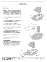
1If anchorage is required, start by locating post positions on oor and install brackets (F)
WARNING: Appropriate fasteners
must be used to attach bracket(s)
to oor. Fasteners are not
provided by Haworth. Consult
with the customer appointed
engineer for fastener
recommendations.
A
F

2-WAY POST 3-WAY POST 4-WAY POST TOP FRAME RAILPOST, UNDERBEAM
EOR
Main Frame
S226
S258
S259
S260
S257
2.2CUSTOMER SERVICE PHONE: 1-800-426-8562
1/4-20 x 1" Hex Head Bolt - Grade 8
(S226)
1/4-20 x 2-1/4" Hex Head Bolt - Grade 8
(S256)
(S258)
5/16 x 7/8" Hex Head Bolt - Grade 8
(S257)
5/16 x 1-1/4" Hex Head Bolt - Grade 8
3/8" x 2" Hex Head Bolt - Grade 8
(S259)
Joint Reinforement Bracket
S256
A A2 A3 B C
D
D1
E
E1
NOTE: As required
for high structural
load applications.
3/8" x 1-3/8" Hex Head Bolt - Grade 8
(S260)

Main Frame - Reinforced Joint Application
Main Frame - Reinforced Joint Application
2.3CUSTOMER SERVICE PHONE: 1-800-426-8562
1/4-20 x 1" Hex Head Bolt
(S226)
(S258)
5/16 x 7/8" Hex Head Bolt
(S257)
5/16 x 1-1/4" Hex Head Bolt
S226
1
1
2
S258
S257
(S258)
5/16 x 7/8" Hex Head Bolt
(S257)
5/16 x 1-1/4" Hex Head Bolt
S258
S257
OR
A
D
D1
E
E1
E
E1

2.4CUSTOMER SERVICE PHONE: 1-800-426-8562
Main Frame Assembly
1
OR
OR
S260
S259
S256
Reinforced Joint
O Mod Rail
Standard-Rail
1/4-20 x 2-1/4" Hex Head Bolt
(S256)
3/8" x 2" Hex Head Bolt
(S259)
S259
Standard Joint
S256
NOTE: Bolt (S256)
is not required.
A
A
A
C
C
S260
C
3/8" x 1-3/8" Hex Head Bolt - Grade 8
(S260)

Main Frame Assembly
2.5CUSTOMER SERVICE PHONE: 1-800-426-8562
2
OR
1/4-20 x 2-1/4" Hex Head Bolt
(S256)
3/8" x 2" Hex Head Bolt
(S259)
S260
S260
S256
S256
CC
S259
A
A
S259
NOTE: Bolt (S256)
is not required.
NOTE: Optional Brace to
assist when assembling
frame. Supplied by others.
Reinforced Joint Standard Joint
3/8" x 1-3/8" Hex Head Bolt - Grade 8
(S260)

Main Frame Assembly - Round
3
(S258)
5/16 x 7/8" Hex Head Bolt
(S257)
5/16 x 1-1/4" Hex Head Bolt
S260
3/8" x 2" Hex Head Bolt
(S259)
2.6CUSTOMER SERVICE PHONE: 1-800-426-8562
C
C
S258
S257
E
E1
C
3/8" x 1-3/8" Hex Head Bolt - Grade 8
(S260)
S259

4
3/8" x 2" Hex Head Bolt
(S259)
Main Frame Assembly - Round
2.7CUSTOMER SERVICE PHONE: 1-800-426-8562
C2
C2
C
3/8" x 1-3/8" Hex Head Bolt - Grade 8
(S260)
S259

1-1/8”
Minimum
1/2”
Minimum
Floor Anchor
6
5
WITHOUT ANCHOR
WITH ANCHOR
2.8CUSTOMER SERVICE PHONE: 1-800-426-8562
A
A
A
A
F
F
F
NOTE: Start leveling from high
spot of oor.
Begin levelers at the minimum
and adjust as needed.

Floor Anchor
7
9
8
10
(S166)
1/4-20 Flange Nut
2.9CUSTOMER SERVICE PHONE: 1-800-426-8562
A
G
H
J
J2
F3
S166
A
A
A
F3

Post, Underbeam EOR
1
2
X
X + 1” = Y
X + 1” = Y
+1”
X
WALL SIDE
OPEN
SIDE
2.10CUSTOMER SERVICE PHONE: 1-800-426-8562
B2
K
K
B2
B2

Install all components to complete wall before next step (Refer to Section 3)
CUSTOMER SERVICE PHONE: 1-800-426-8562 2.11
Post, Underbeam EOR
3
2
1
S100
#12 x 1/2" Screw
(S100)
C
B
4
K
NOTE: Install
screws loosely.
L
M
OR

2.12CUSTOMER SERVICE PHONE: 1-800-426-8562
Post, Underbeam EOR
5
1
Install carpet gripper and secure post
NOTE: Adjust leveler so
the post is tight to top rail.
0.0”
C
B
OR
SMOOTH CARPET
B2
B2
B2
2
S100
#12 x 1/2" Screw
(S100)
C
B
/