Page is loading ...

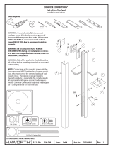
Tools Required
#2
A
B
A
3 CIRCUIT 3 + 1 CIRCUIT 2 + 2 CIRCUIT
BLACK GREEN BLUE
F
3 CIRCUIT 3 + 1 CIRCUIT 2 + 2 CIRCUIT
BLACK GREEN BLUE
NOTE: Connectors are color coded
and keyed to assure polarity.
WARNING: Do not electrically interconnect modular
power distribution systems powered from two dierent
power feed units. This poses a SHOCK HAZARD to service
personnel and will cause RISK OF FIRE due to excessive
circulating currents.
WARNING: All circuit power MUST REMAIN DISCONNECT-
ED during any installation or removal of electrical
components and raceway covers to avoid SHOCK
HAZARDS.
NOTE: Connections of this modular power distribution
component MUST be done by a licensed electrician, who
must control the size and loading of each branch circuit.
The person or group installing Haworth products is
responsible for complying with all applicable building and
electrical code requirements.
1 of 7 7029-9602
Part No: Rev:
Page:
E.C.O. No:
CUSTOMER SERVICE PHONE: 1-800-426-8562
2298-749
POWER BASE®
3 & 4 Circuit Concealed Base Feed
Installation Instructions
Remove cover (B)
1
1
NOTE: Polarity keys (F)
are on 3 circuit connector
heads only.

FOR COMPOSE INSTALLATION
FOR PREMISE INSTALLATION
FOR PLACES INSTALLATION
2 of 7 7029-9602
Part No: Rev:
Page:
E.C.O. No: 2298-749
Install base feed (A)
1
2a
NOTE: Conduit
is supplied by
customer.
Install base feed (A)
1
2b
NOTE: Cut hole in
bottom or side of
raceway cover if
necessary.
Install base feed (A)
1
2c
NOTE: Cut hole in
bottom or side of
raceway cover if
necessary.
B
C
NOTE: Conduit is
supplied by customer.
A
NOTE: 36” minimum
panel widths.
NOTE: 30” minimum
panel widths.
NOTE:
Conduit is
supplied by
customer.
C
A
B
E
CNOTE: Conduit is
supplied by customer.
A
A
D
B
NOTE: 36” minimum
panel widths.

FOR PREMISE INSTALLATION
C
A
B
3 of 7 7029-9602
Part No: Rev:
Page:
E.C.O. No:
CUSTOMER SERVICE PHONE: 1-800-426-8562
2298-749
Install base feed (A)
1
2a
Install base feed (A)
1
2b
NOTE: Cut hole in
bottom or side of
raceway cover if
necessary.
Install base feed (A)
1
2c
NOTE: Cut hole in
bottom or side of
raceway cover if
necessary.
FOR COMPOSE INSTALLATION
FOR RESIDE DESKING INSTALLATION
B
A
C
A
E
C
D
A
D
#10-12 x 5/8" Pan Head Screw
A
D
NOTE:
Conduit is
supplied by
customer.
NOTE: 36” minimum
panel widths.
NOTE: 36” minimum
panel widths.

4 of 7 7029-9602
Part No: Rev:
Page:
E.C.O. No:
CUSTOMER SERVICE PHONE: 1-800-426-8562
2298-749
1
2a
1
3a
1
3b A
Install bracket (E)
Install base feed (A)
C
A
D
AB
BASE APPLICATION
E
FOR COMPOSE BENCHING INSTALLATION
#10-24 x 1/2" Screw
Self Drilling
NOTE: 24” minimum
panel widths.

1
3c Install base feed (A)
5 of 7 7029-9602
Part No: Rev:
Page:
E.C.O. No:
CUSTOMER SERVICE PHONE: 1-800-426-8562
2298-749
FOR COMPOSE CONNECTIONS INSTALLATION
D
AB
A

6 of 7 7029-9602
Part No: Rev:
Page:
E.C.O. No:
CUSTOMER SERVICE PHONE: 1-800-426-8562
2298-749
1
2a
1
3a
1
3b
NOTE: Conduit
is supplied by
customer.
NOTE: Center bracket (E)
vertically on side panel.
NOTE: Conduit
is supplied by
customer.
42", 72"
Install base feed (A)
A
B
Install base feed (A)
B
D
A
OR
Install bracket (E)
FOR BESIDE STORAGE INSTALLATION
E
23"-29"
#10-12 x 5/8" Pan Head Screw
C
L

7 of 7 7029-9602
Part No: Rev:
Page:
E.C.O. No:
CUSTOMER SERVICE PHONE: 1-800-426-8562
2298-749
NEUTRAL
GROUND
Three-Circuit, Separate Neutrals WIRING DIAGRAM
PHASE
A
PHASE
B
PHASE
C
NEUTRAL
GROUND
Three 208Y/120V Phase
Circuit Panel
On a 3-phase circuit panel, circuits are
distributed as shown.
Three 208Y/120V Phase
Circuit Panel
On a 3-phase circuit panel, circuits are
distributed as shown.
On a 3 a single wire phase circuit panel, circuits are
distributed as shown.
On a 3-phase circuit panel, circuits are
distributed as shown.
PHASE
A
PHASE
C
NEUTRAL
GROUND
Three Wire Single 120Y/240V Phase
Circuit Panel
On a 3 wire single phase circuit panel, circuits
are distributed as shown.
Circuit 1Neutral, N1- White
Circuit 2 Neutral, N2- White/Red
Circuit 3 Neutral, N3- White/Blue
Four-Circuit, 3+1
PHASE
A
PHASE
B
PHASE
C
NEUTRAL
GROUND
Circuit 1, 2, & 3 Neutral, N1- Grey
Circuit 4 Neutral, N2- Grey/Red
N1
N2
N3
G1
G2
L1
L2
L3
= WHITE (12GA)
= WHITE/RED (12GA)
= WHITE/BLUE (12 GA)
= BARE COPPER (12GA)
= GREEN/YELLOW (12GA)
= BLACK (12GA)
= RED (12GA)
= BLUE (12GA)
3 CIRCUIT WIRE COLOR
PHASE
A
PHASE
C
Circuit 1 & 2 Neutral, N1- Grey
Circuit 3 & 4 Neutral, N2- Grey/Red
PHASE
A
PHASE
B
PHASE
C
NEUTRAL
GROUND
Circuit 1 Hot- Black
Circuit 2 Hot- Red
Circuit 3 Hot- Blue
Circuit 4 Hot- Violet
System Ground G1- Bare
Isolated Ground G2- Green/Yellow
Circuit 1 Hot- Black
Circuit 2 Hot- Red
Circuit 3 Hot- Blue
N1
N2
G2
G1
L1
L2
L3
L4
= GREY (10GA)
= GREY/RED (10GA)
= GREEN/YELLOW (12GA)
= BARE COPPER (12GA)
= BLACK (12GA)
= RED (12GA)
= BLUE (12GA)
= VIOLET (12GA)
4 CIRCUIT WIRE COLOR
Four-Circuit, 2+2
Three Wire Single 120/240V Phase
Circuit Panel
Three 208Y/120V Phase
Circuit Panel
Circuit 4 Hot- Violet
Circuit 1 & 2 Neutral, N1- Grey
Circuit 3 & 4 Neutral, N2- Grey/Red
Circuit 1 Hot- Black
Circuit 2 Hot- Red
Circuit 3 Hot- Blue
Circuit 4 Hot- Violet
System Ground G1- Bare
Isolated Ground G2- Green/Yellow
System Ground G1- Bare
Isolated Ground G2- Green/Yellow
Circuit 1 Hot- Black
Circuit 2 Hot- Red
Circuit 3 Hot- Blue
System Ground G1- Bare
Isolated Ground G2- Green/Yellow
Circuit 1Neutral, N1- White
Circuit 2 Neutral, N2- White/Red
Circuit 3 Neutral, N3- White/Blue
Circuit 1 Hot- Black
Circuit 2 Hot- Red
Circuit 3 Hot- Blue
System Ground G1- Bare
Isolated Ground G2- Green/Yellow
Haworth Power Base components, are oered in three dierent wiring
schematics to allow you to match your specic wiring strategy to any typical
building wiring plan.
All the components in the electrical system must use the same wiring
schematic. The components are color coded and keyed to assure correct
polarity.
Black = Three-circuit, separate neutrals
Green = Four-circuit, 3+1
Blue = Four-circuit, 2+2
In the three-circuit, separate neutral schematic, each circuit is supported
with its own neutral and a common ground (L1 & N1, L2 & N2, L3 & N3).
In the four-circuit 3+1 schematic, Circuits 1, 2, and 3 are
supported with one shared neutral N1. Circuit 4 is
supported with a separate neutral N2.
In the four-circuit, 2+2 schematic, circuits 1 and 2 are
distributed from two dierent phases and are supported
with one shared neutral N1. Circuits 3 and 4 are
distributed from two dierent phases and supported by
their own shared neutral N2.
/
